Table of Contents
Advertisement
Quick Links
Advertisement
Table of Contents

Related Manuals for Yaesu DR2XLAN


Summary of Contents for Yaesu DR2XLAN
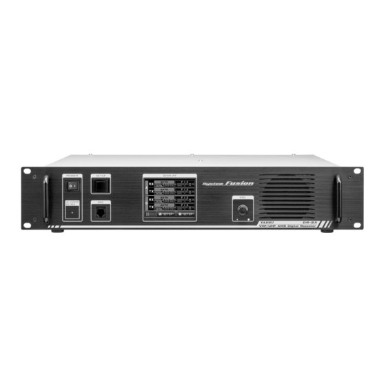
- Page 1 VHF/UHF C4FM/FM 50W AMS DIGITAL REPEATER Operating Manual...
-
Page 2: Table Of Contents
Company and product names described in this manual are trademarks and registered trademarks of their respective companies. Unauthorized reproduction or copying of a part or all of the copyrights owned by Yaesu Musen Co., Ltd. in any form whatsoever is strictly prohibited. -
Page 3: Introduction
Congratulations on your purchase of the DR-2X/DR-2XE Yaesu 144/430MHz Dual Band Dual Receive C4FM/ FM Digital Repeater. The YAESU DR-2X/DR-2XE is a C4FM digital / analog FM dual mode and dual receive repeater that covers the VHF and UHF amateur radio bands. DR-2X/DR-2XE incorporates the use of Analog FM communication integrated with the C4FM digital communication through its unique AMS capability. - Page 4 DANGER Do not use the device in “locations or aircraft and vehicles where Use good engineering, proper grounding and protective devices to its use is prohibited” such as in hospitals and airplanes. protect the repeater from power surges, lightening and electrical This may exert an impact on electronic and medical devices.
-
Page 5: Setting Up The Repeater
Setting up the Repeater Safety measures for installation Note the following precautions when installing this repeater: Use good engineering, proper grounding and protective devices to protect the repeater from power surges, lightening and electrical damage via the power and external antenna connections. ... -
Page 6: Connecting Antenna Cables
Connecting Antenna Cables The figure above shows the rear panel of the DR-2X. 1 When using a duplexer, plug the coaxial cables from the TX ANT and RX ANT terminals into the jacks of the duplexer, and tighten the connectors. 2 Plug in the terminal of the coaxial cable connected to the antenna into the jack of the duplexer, and turn to tighten. -
Page 7: Connecting The Power Supply
Connecting the Power Supply Connection for DR-2X (US and Asian versions) z Main power Use an AC outlet capable of supplying AC 100-240V at 50 or 60Hz. 1 Insert the socket of the provided AC power cord into the AC IN jack at the rear of the repeater. 2 Insert the plug of the provided AC power cord into the AC outlet. -
Page 8: Connecting External Devices
Make sure to switch off the power to the radio before connecting the cable. z When using the SCU-20, PC connection cable, a dedicated driver must be installed in the personal computer. Download and use the driver and installation manual from the YAESU website. DR-2X / DR-2XE Operating Manual... -
Page 9: Accessories And Options
Accessories and Options Supplied Accessories AC Power Cord (T9027682) ø1 ........................1 DC Power Cord with Fuse (T9026115) ......................1 Spare Fuse 15 A (Q0000075) ........................1 5 A (Q0000143) ø1 ......................1 Case Legs (S4000052) ........................... 4 PC Connection Cable SCU-20 ........................1 Operating Manual (this manual) ........................ -
Page 10: Rear Panel
Rear Panel DR-2X (US and Asian versions) ① ② ③ ④ ⑤ ⑩ ⑪ ⑬ ⑥ ⑦ ⑧ ⑨ ⑫ ⑭ DR-2XE (European and Australian versions) ① ② ③ ④ ⑤ ⑩ ⑪ ⑥ ⑦ ⑧ ⑫ ⑨ CH- A TX Antenna Terminal (N-type connector, 50 ohms) Connect to the transmitting antenna (downlink of the CH-A) with the coaxial cable. -
Page 11: Initial Set Up
1. Initial set up Turn the power on Press the POWER switch. The power will be switched ON, and the power supply monitor (LED indicator) will illuminate. z When the power is supplied from the AC IN jack, the indicator illuminates in green (DR-2X only). -
Page 12: Set Up Operation Mode
2. Set up Operation Mode When the Power Switch is turned ON, Operation Mode screen appears. This screen is for normal operation. The DR-2X/DR-2XE could be set up with two frequencies for the uplink and the downlink and also different operation modes for each frequency. -
Page 13: Set Up Frequency
RX indicator This indicator shows green when a signal is received and white when there is no signal. TX indicator This indicator shows red when the repeater transmits and white when there is no transmit. PRI indicator This indicator shows when the channel is set to the Priority Channel. CNTL indicator This indicator shows when CH-B is set as the dedicated control channel, and it does not repeat. -
Page 14: Select Downlink Antenna
After completing the input frequency, the input popup screen automatically disappears and the input frequency is set. Input the downlink frequency in the same way. Touch [ Back ] to return to the operation mode screen, and touch [ B SETUP ] on the bottom of the screen to display the CH-B frequency set up screen, then set the uplink and downlink frequency. -
Page 15: Set Up Priority Channel
4. Set up Priority Channel Priority Channel In the dual receive function, one channel may be set as the priority channel. Normal operation mode: • When CH-A and CH-B are set to different uplink frequencies, a signal on either uplink frequency will inhibit reception on the other channel until the first channel communication is complete. -
Page 16: Set Up Other Functions
5. Set up Other Functions Adjusting the squelch level z When the squelch level is set to “open” the repeater will transmit, so the TX output must be connected to the duplexer and antenna. z Use extreme caution when making the squelch adjustment or measurement with a signal generator. Do not connect the signal generator to the duplexer antenna port. -
Page 17: Base Mode Operation
6. Base mode operation The repeater can be used as a VHF/UHF base station by connecting an optional MH-48A6JA or MH-42C6J microphone to the “MIC” jack on the front panel. The base mode operation is available only on CH-A. MH-48A6JA or MH-42C6J DR-2X / DR-2XE Operating Manual... -
Page 18: Set Up Dg-Id Number
In order to use the DG-ID feature, update the C4FM digital transceivers to the latest firmware compatible with the DG-ID feature. • The latest firmware for each transceiver is available on the YAESU website. • The DR-2X/DR-2XE will repeat on the downlink, only the uplink signals with the corresponding DG-ID number if the DG-iD number is set to an arbitrary number from “01”... -
Page 19: Setting The Dg-Id Number
Setting the DG-ID Number 1 Touch [ A SETUP ] or [ B SETUP ] to display the frequency set up screen, S E T U P R X x . x x T X . x S E T U P R X x . x x T X . x then touch [ F ] on the bottom of the screen. -
Page 20: Default Id Setting
Default ID Setting 1 Touch [ A SETUP ] or [ B SETUP ] to display the frequency set up screen, S E T U P R X x . x x T X . x S E T U P R X x . x x T X . x then touch [ F ] on the bottom of the screen. - Page 21 Steps 6 to 10 are the procedures to enable listing the DG-ID of the repeaters to be linked. If the list display is not required, go to step 11. 6 Touch [ Registered DG-ID ] twice. Group 1 DG-ID The registration screen of the repeater to be linked as a group is displayed.
-
Page 22: Dg-Id Tot Setting
DG-ID TOT Setting Setting accessible time of the other DG-ID other than the Default DG-ID. 1 Touch [ A SETUP ] or [ B SETUP ] to display the frequency set up S E T U P R X x . x x T X . x screen, then touch [ F ] on the bottom of the screen. -
Page 23: Set Up Dp-Id
8. Set up DP-ID Digital Personal Identification ( DP-ID ) Digital Personal Identification (DP-ID) is the digital ID number each transceiver is programmed with. The system manager may operate the DR-2X/DR-2XE repeater functions, and the emergency communication, by registering the DG-ID number of the controlling C4FM digital transceiver to the DR-2X/DR-2XE. When receiving the uplink signal containing the DP-ID that is registered to the DR-2X/DR-2XE, the signal is received and transmitted on the downlink preferentially. - Page 24 z Delete the registered DP-ID 1 Touch [ A SETUP ] or [ B SETUP ] to display the frequency set up screen, then touch [ F ] on the bottom of the screen. 2 Touch [ ID MODE ] to select the “DP-ID”. S E T U P R X x .
-
Page 25: Basic Set Up And Operations
9. [ Example ] Basic Set up and Operations Stand Alone Operation User 3 User 4 System Manager DP-ID registered RPT1 DG-ID: TX00RX00 DG-ID: TX01RX00 User 2 User 1 DG-ID: TX01RX00 DG-ID: TX01RX00 DG-ID: Default: 01 Setting Content (Frequencies are shown for example only, use your repeater coordinated frequencies) AUTO AMS 448.700 MHz CH-A... -
Page 26: Advanced Set Up And Operations
10. [ Example ] Advanced Set up and Operations IMRS (Internet-linked Multi-site Repeater System) The repeater, installed the optional LAN Unit LAN-01A and connected the multiple DR-2X/DR-2XE repeaters via the Internet, may be accessed as stand-alone or as a group repeater (Up to 99 units). System Manager RPT-A RPT-B... - Page 27 While the TOT is activated, transceivers may communicate without changing the transmit DG-ID for a certain period of time (TOT operating time) regardless of the transceiver DG-ID. ø: Selectable from 0/30sec/1min/1.5min/2min/2.5min/3min/4min/5min/10min/CONT. (Default 1min) • When deactivating the TOT, transceiver beeps 2 times to notify that the TOT is deactivated with the downlink signal from all the linked repeaters.
-
Page 28: Remote Controls
11. Remote Controls Setting the remote control • Remote control of the DR-2X/DR-2XE repeater can be performed in either C4FM digital mode or analog FM mode. For C4FM digital mode, use the FTM-100D, FTM-400D, FTM-400XD or FTM-3200D transceiver. For security reasons, we recommend using a mobile C4FM transceiver with the DP-ID that is registered to the DR-2X/DR-2XE repeater. -
Page 29: C4Fm Digital Control
C4FM DIGITAL CONTROL • Requires the optional LAN Unit “LAN-01A” for digital voice storage and playback functions. • Set the operation mode to “AUTO” or “FIX DIGITAL”. • The transceivers compatible with the remote-control are the FTM-400D, FTM-400XD, FTM-100D and FTM- 3200D. -
Page 30: Change The Remote Command
Change the remote command To change the factory command codes. Touch [ A SETUP ] or [ B SETUP ] on the operation mode screen. S E T U P R X x . x x T X . x ... -
Page 31: Actual Remote Control Procedure
If the FTM-400D/XD, FTM-100D or FTM-3200D firmware is not compatible with the DP-ID function, update the transceiver to the latest firmware to utilize the DP-ID functions. z The latest firmware is available on the YAESU website. When controlling remotely with the FT-991A 1 Please confirm that the FT-991A DP-ID is registered on the DR-2X/DR-2XE repeater. -
Page 32: Voice Messages
13. Voice messages Voice messages are a very useful feature to communicate messages to all club members. For example, when you plan a breakfast meeting on Sunday morning, if you record the location and time with the remote control, the message is transmitted from the repeater at a predetermined interval and number of times. For example, it is possible to set the message to announce ten times at an hourly interval. -
Page 33: Setting The Interval And Number Of
14. Setting the interval and number of voice messages The DR-2X/DR-2XE has a message function that automatically transmits the recorded message on the downlink frequency at specified intervals and number of times. Setting the transmission interval of the message: 1 Touch [ A SETUP ] or [ B SETUP ] to display the frequency set up S E T U P R X x . -
Page 34: Operate Message Function At The Dr-2X/Dr-2Xe Site
15. Operate message function at the DR-2X/DR-2XE site To Record a message for Analog FM: 1 Connect an optional MH-48A6JA or MH-42C6J microphone to the “MIC” jack on the front panel of the DR-2X/DR-2XE. 2 Touch [ A SETUP ] or [ B SETUP ] on the bottom of the Operation Mode Screen, then touch [ F ] . - Page 35 How to erase recorded contents: 1 Touch [ A SETUP ] or [ B SETUP ] on the bottom of the Operation Mode Screen, then touch [ F ] . 2 Touch [ MODE/REMOTE ] . S E T U P R X x . x x T X . x 3 Touch [ COMMAND ] twice.
-
Page 36: Set Up Various Functions
16. Set Up Various Functions Using the setup menu, the various functions of the repeater can be customized to match the desired applications. Items to be adjusted can be selected from the respective lists, and the settings entered or selected that are appropriate for the intended repeater operation. -
Page 37: Setting The Half Deviation Operation
Setting the half deviation operation 1 Touch [ A SETUP ] or [ B SETUP ] , and then touch [ F ] . S E T U P R X x . x x T X . x 2 Touch [ DEVIATION ] to display “NARROW”. ... -
Page 38: Set The Tone Signal Type For Analog Fm Mode
Set the tone signal type for analog FM mode 1 Touch [ A SETUP ] or [ B SETUP ] , then touch [ F ] , and then touch [ SQL ] . S E T U P R X x . x x T X . x 2 Select [ RX SQL ] to set the tone signal type during reception, or select ... -
Page 39: Setting The Sql Hysteresis
Set announcement time interval 1 Touch [ A SETUP ] or [ B SETUP ] , then touch [ F ] . S E T U P R X x . x x T X . x 2 Touch [ ID ANNOUNCE ] , then touch [ INTERVAL ] . ... -
Page 40: Setting The Display Turn-Off Time
Setting the display turn-off time 1 Touch [ A SETUP ] or [ B SETUP ] , then touch [ F ] , and then touch [ MODE/REMOTE ] . 2 Touch [ DISPLAY TIMER ] to display “ON” or “OFF” . REMOTE/COMMAND/DISP TIMER The set value will change between “... -
Page 41: Restoring Default Settings (Factory Reset)
17. Restoring Default Settings (Factory Reset) 1 Turn the DR-2X/DR-2XE OFF. POWER SETUP 2 Press and hold in the [ SETUP ] button while turning the transceiver Continue pressing the [ SETUP ] button until the operation mode screen appears on the display. 3 Touch [ A SETUP ] . -
Page 42: Connect To The Hri-200 Node Station
18. Connect to the HRI-200 node station To use WIRES-X with DR-2X/DR-2XE, connect HRI-200 directly to the 10-pin plug on the back of the DR-2X/ DR-2XE. Alternatively, there is a method the HRI-200 Node station may be located in a place different from the repeater site. - Page 43 While pressing and holding the [ SETUP ] button, press the [ POWER ] switch. POWER SETUP While the “YAESU” logo is being displayed, release the [ SETUP ] button. “HRI+REPEATER MODE” will appear on the display. Touch [ OK? ].
-
Page 44: Remote Operation With External Controller
19. Remote Operation with External Controller Repeater operation may be controlled remotely by connecting an external controller through the [ CONTROL I/O ] connector at the back of the repeater. The following features are available while in remote operation: • Change the communication mode of repeater transmit and receive •... - Page 45 Pin No Pin Name Descriptions [ L ] GND: Remote mode [ H ] OPEN: Repeater mode EXT I/O Input [ L ] GND: EXT PTT ON [ H ] OPEN: EXT PTT OFF When this pin is pulled low by an external device, it keys the repeater transmitter.
- Page 46 Pins 6, 7, 8, and 9 Functions Controlled by Operation Mode Pin No Pin Name Receive Mode In Repeater / Remote Mode TONE IN Digital Invalid Analog Invalid AF IN Digital Invalid Analog Invalid DISC OUT Digital Invalid Analog Discriminator output AF OUT Digital Demodulated digital audio output...
- Page 47 Setting to connect the repeater controller S-COM7330 Set up instructions to interface the Triple Repeater Controller S-COM7330 with the DR-2X/DR-2XE. Modification of S-COM7330 1 Remove the 6 screws from each side and 2 screws from the top cover of the S-COM7330, then remove the top cover. 2 Change Jumper pin J10C or J11C or J3C and adjust the semi fixed.
- Page 48 Connecting S-COM7330 S-COM7330 PORT 3 PORT 2 PORT 1 RS232-2 RS232-1 INIT RESET DC 9V-36V This connection needs programming of S-COM7330. Repeater 1 Repeater 2 Repeater 3 DR-2X / DR-2XE Operating Manual...
-
Page 49: Installation Of The Optional Accessories
20. Installation of the Optional Accessories Installing the optional Voice Guide Unit FVS-2 Turn the DR-2X/DR-2XE [ POWER ] switch to “OFF”. Disconnect all the cables from the DR-2X/DR-2XE. Remove the 4 screws from each side and 7 screws from the top cover of the DR-2X/DR-2XE, then remove the top cover. -
Page 50: Specifications
21. Specifications z General Frequency range : 144 to 146 MHz, 430 to 440 MHz or 144 to 148 MHz, 430 to 450 MHz Channel steps : 5 / 6.25 kHz Emission type : F1D, F2A, F2D, F3E, F7W 16K0F1D F1D - Frequency modulation data transmission, double sideband, without using a modulating subcarrier 16K0F2D F2D - Frequency modulation data transmission, using a modulating subcarrier... -
Page 51: After-Market Services
Contact Yaesu Service Center for non-warranty repairs Repairs will be made at the user’s expense if normal functions can be maintained after the repair. Please check with the retail store or Yaesu service center for more information. Arrow Mark side up... - Page 52 Note DR-2X / DR-2XE Operating Manual...
- Page 53 Note DR-2X / DR-2XE Operating Manual...
- Page 54 Note DR-2X / DR-2XE Operating Manual...
- Page 55 EU Declaration of Conformity We, Yaesu Musen Co. Ltd of Tokyo, Japan, hereby declare that this radio equipment DR-2XE is in full compliance with EU Radio Equipment Directive 2014/53/EU. The full text of the Declaration of Conformity for this product is available to view at http://www.yaesu.com/jp/red...
- Page 56 Copyright 2020 YAESU MUSEN CO., LTD. All rights reserved. No portion of this manual may be reproduced without the permission of YAESU MUSEN CO., LTD. YAESU MUSEN CO., LTD. Tennozu Parkside Building 2-5-8 Higashi-Shinagawa, Shinagawa-ku, Tokyo 140-0002 Japan YAESU USA 2002H-DS-1 6125 Phyllis Drive, Cypress, CA 90630, U.S.A.
Need help?
Do you have a question about the DR2XLAN and is the answer not in the manual?
Questions and answers