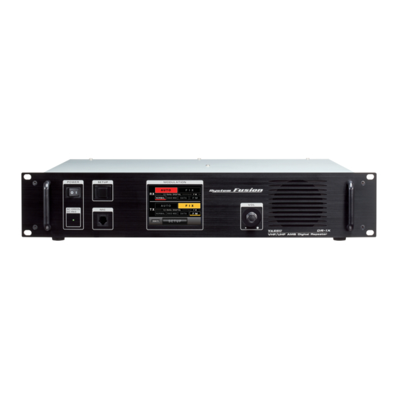
Yaesu DR-1X Operating Manual
System fusion 144/430mhz 50w vhf/uhf ams digital repeater c4fm fdma/fm
Hide thumbs
Also See for DR-1X:
- Technical supplement (113 pages) ,
- Operating manual (48 pages) ,
- Installation instructions manual (10 pages)

Related Manuals for Yaesu DR-1X


Summary of Contents for Yaesu DR-1X
- Page 1 DR-1X / DR-1XE 144/430MHz 50W VHF/UHF AMS DIGITAL REPEATER C4FM FDMA/FM Operating Manual Before Using Installation and Connection Operations Appendix...
-
Page 2: Introduction
Company and product names described in this manual are trademarks and registered trademarks of their respective companies. Unauthorized reproduction or copying of a part or all of the copyrights owned by Yaesu Musen Co., Ltd. in any form whatsoever is strictly prohibited. -
Page 3: Table Of Contents
Connection of an external microphone or PTT switch ..16 Connection to a personal computer ........16 Connection to an external controller ........17 To use DR-1X/DR-1XE in Remote mode ......18 Repeater Operation ..............19 Basic Operations ..............19 Turning the power on ............19 Switching the power off .............19... -
Page 4: Before Using
Before Using Safety Precautions (make sure to read these) Make sure to read this manual in order to use this radio safely and correctly. Note beforehand that the company shall not be liable for any damages suffered by the customer or third parties in using this product, or for any failures and faults that occur during the use or misuse of this product, unless otherwise provided for under the law. - Page 5 Safety Precautions (make sure to read these) Do not use fuses other than those specified. Follow the instructions given when installing items sold Doing so may result in fire and equipment failure. separately and replacing the fuse. This may result in fire, electric shock and equipment failure. Do not allow metallic objects such as wires and water to get inside the product.
-
Page 6: Accessories
5 A (Q0000143) ............1 Case Legs (S4000052) ................ 4 PC Connection Cable SCU-20 (T9101621) ......... 1 Operating Manual (this manual) ............1 Warranty Certificate ................1 *1: For DR-1X only Options DTMF Microphone MH-48A6JA Hand Microphone MH-42C6J Voice Guide Unit FVS-2... -
Page 7: Name And Function Of Each Component
Power supply monitor (LED indicator) • When the indicator illuminates in green, the power is supplied from the AC IN jack (DR-1X only). • When the indicator illuminates in red, the power supply is backed up through the BACKUP terminals (13.8 V DC). -
Page 8: Rear
Name and Function of Each Component Rear Note The figure above shows the rear panel of the DR-1X. TX ANT terminal Connect to the transmitting antenna (down link) with the coaxial cable. The output impedance requirement is 50 ohms. -
Page 9: Explanation Of The Screen
Name and Function of Each Component Explanation of the screen Operation mode screen Receive (up link) band display area Transmit (down link) band display area Operation mode display area [AUTO] Touch here to activate the AMS (automatic mode select) function. The communication mode switches automatically according to the received/transmitted signal types. - Page 10 Name and Function of Each Component Setup mode screen Receive (up link) band display area Transmit (down link) band display area Touch key display area [BACK] Touch here to return to the operation mode screen. [SQL] Touch here to set the squelch level of the receiver. [Tx PWR] Touch here to set the transmitter output level.
-
Page 11: Installation And Connection
Installation and Connection Setting up the Repeater Safety measures for installation Note the followings precautions when installing this repeater. Use good engineering, proper grounding and protective devices to protect the repeater from power surges, lightening and electrical damage via the power and external antenna connections. ... -
Page 12: About Electrical Grounding
Setting up the Repeater About electrical grounding The DR-1X/DR-1XE repeater, like any other communications apparatus, requires an effective ground system for maximum electrical safety and best communications effectiveness. A good ground system can contribute to station efficiency in a number of ways: •... -
Page 13: Connecting The Antenna
Note The figure above shows the rear panel of the DR-1X. To use a duplexer prepared by yourself, plug in the terminal of the coaxial cables from the TX ANT and RX ANT terminals into the jacks of the duplexer, and turn to tighten... -
Page 14: Connecting The Power Supply
Connecting the Power Supply Connection for DR-1X ● Main power Caution z Use an AC outlet capable of supplying AC 100 to 240 V at 50 or 60 Hz. Insert the socket of the provided AC power cord into the AC IN jack at the rear of the repeater Insert the plug of the provided AC power cord into the AC outlet ●... -
Page 15: Connection For Dr-1Xe
Connecting the Power Supply Connection for DR-1XE Follow the outline in the illustration regarding the proper connection of the DC power cable. The DC power connector for the DR-1XE must only be connected to a DC source providing 13.8 V DC (±15 %), and capable of at least 10 A of current. -
Page 16: Connecting External Devices
• Make sure to switch off the power to the radio before connecting the cable. • When using the PC connection cable “SCU-20”, a dedicated driver needs to be installed in the personal computer. Download and use the driver and installation manual from the YAESU website. -
Page 17: Connection To An External Controller
To control the DR-1X/DR-1XE remotely, optional cables can be used to connect the repeater to an external controller. Use the [CONTROL I/O] connector at the back of the repeater to connect with the external controller. To interface the DR-1X/DR-1XE with an external controller, additional cables with a 15-pin mini d-sub connector are needed to connect to the [CONTROL I/O] connector. Your controller may also require rewiring. -
Page 18: To Use Dr-1X/Dr-1Xe In Remote Mode
Analog audio output Caution Even when using the DR-1X/DR-1XE with an external controller, the COR, analog and digital IDs, TOT, DSC/CTCSS, TX power, etc. are already controlled by the DR-1X/DR-1XE internal control. These internal controls cannot be disabled. The external controller must not conflict with these functions. -
Page 19: Repeater Operation
The power will be switched on, and the power supply monitor (LED indicator) will illuminate. Tips • When the power is supplied from the AC IN jack, the indicator illuminates in green (DR-1X only). • When the power is supplied through the BACKUP terminals (13.8 V DC), the indicator illuminates in red. -
Page 20: Turning The Display On And Off
Basic Operations Turning the display on and off Press the SETUP button for 1 second to turn the display off Press the SETUP button for 3 seconds to turn the display on The display can be set to turn off automatically after a period of time with no operation. See “Setting the display turn-on time” (Page 37) for details. Adjusting the volume Turn the VOL knob The monitor speaker audio volume of the received (up link) signal will increase when... -
Page 21: Switching The Operating Mode
Basic Operations Switching the operating mode The operating mode can be switched between the AUTO mode in which the communication mode switches automatically corresponding to the received/transmitted signal types, and the FIX mode in which the signals are always received/transmitted in the previously selected communication mode. -
Page 22: Switching The Communication Mode
Do not connect the signal generator to the duplexer antenna port. To avoid damaging the test equipment, connect the signal generator directly to the RX antenna connector on the DR-1X/DR-1XE. Touch [SETUP]... -
Page 23: Adjusting The Transmit Power
Basic Operations Touch [SQL] When [SQL] turns orange, the VOL meter below the frequency of the RX band will change to the SQL meter showing the squelch level setting. Touch [▲] or [▼] to adjust the squelch level The level will be displayed in the SQL meter. Touch [BACK] The squelch level is set and the display will return to the previous screen. -
Page 24: Setting The Tx Inhibit
Basic Operations Setting the TX Inhibit Touch [SETUP] on the operation mode screen The setup mode screen will appear. Touch [F] in the setup mode screen The setup menu will appear. Touch [MODE/REMOTE] The menu list will appear. Select [TX INHIBIT] Touch [TX INHIBIT] The set value will change between [OFF] and [ON] each time it is touched. -
Page 25: Remote Operation
Remote Operation You can control the repeater operation remotely by connecting an external controller through the [CONTROL I/O] connector at the back of the repeater (see “Connection to an external controller” (Page 17)). The following features are available while in remote operation: • Changing the communication mode of repeater transmission and reception • Turning the RX and TX tone signal “ON” or “OFF” •... -
Page 26: Control From External Controller
AF IN is usually used for analog modulation input with a packet speed of 1200 bps, however, to input C4FM digital signals for digital modulation operations, enter the DR-1X/DR-1XE Repeater mode, then touch the up-link frequency display area to change the packet speed to 9600bps (see the next page). -
Page 27: Base Station Operation
Base Station Operation You can use the repeater as a VHF/UHF base station by connecting an optional MH-48A6JA microphone to the [MIC] jack on the front panel. Transmitting C4FM digital signals For digital modulation operation, the packet speed (data transmission rate) of the repeater must be set to 9600 bps, remember to change the default setting from 1200 bps. If the repeater is expected to transmit digital modulation signals while in base station operation, set the packet speed to 9600 bps before starting base station operation as below. -
Page 28: Setting Up The Repeater
Setting up the Repeater Using the setup menu, the various functions of the repeater can be customized to match the method of use. You can select the items that you would like to adjust from the respective lists and enter or select the appropriate settings for the intended repeater operation. Setup menu basic operations Touch [SETUP] on the operation mode screen The setup mode screen will appear. -
Page 29: Setting The Frequency
Setting up the Repeater Setting the frequency Touch the TX or RX band area. The number input screen will appear. Touch a number key The touched number will be displayed at the top of the screen. Tips • Each time [ ] is touched the cursor will move to the left and erase one character. -
Page 30: Setting The Tone Signals
Setting up the Repeater Setting the tone signals Setting the tone frequency Touch [F] in the setup mode screen The setup menu will appear. Touch [SIGNALING] The menu list will appear. Select [TONE SQL FREQ] Touch [▲] or [▼] The set value will change each time it is touched. Tips •... -
Page 31: Switching The Tone Signal Types
Setting up the Repeater Touch [▲] or [▼] The set value will change each time it is touched. Tips • DCS codes between 023 and 754 can be selected. • Factory default: 023 Touch [BACK] The setting is determined and the display will return to the setup menu. Switching the tone signal types Touch [F] in the setup mode screen The setup menu will appear. -
Page 32: Setting The Digital Squelch Code
Setting up the Repeater Setting the digital squelch code Touch [F] in the setup mode screen The setup menu will appear. Touch [DSQ CODE] The menu list will appear. Touch [▲] or [▼] The set value will change each time it is touched. Tips •... -
Page 33: Setting The Id Announcement
Setting up the Repeater Touch a character key The touched character will be displayed at the top of the screen. Tips • One character to the left of the cursor is erased when [ ] is touched. • The screen changes to the input screen for numbers and alphabet each time [ABC] is touched. •... -
Page 34: Setting The Announcement Output Level
Setting up the Repeater Setting the announcement output level Touch [F] in the setup mode screen The setup menu will appear. Touch [ID ANNOUNCE] The menu list will appear. Select and touch [ANNOUNCE] The menu list will appear. Select and touch [ANNOUNCE LEVEL] The set value will change in the following sequence each time it is touched. -
Page 35: Setting The Announcement Time Interval
Setting up the Repeater Select and touch [CW ID SPEED] The set value will change in the following sequence each time it is touched. “16wd/min” → “18wd/min” → “20wd/min” → “22wd/min” → “24wd/min” Factory default: 20wd/min Note When operating in the USA the CW ID SPEED setting time must not exceed 20 words per minute when keyed by an automatic device, to comply with the FCC rule Part 97: Sec. -
Page 36: Setting The Tot (Timeout Timer)
Setting up the Repeater Setting the TOT (timeout timer) Touch [F] in the setup mode screen The setup menu will appear. Touch [TOT] The menu list will appear. Touch [▲] or [▼] The set value will change in the following sequence each time it is touched. “OFF” → “30sec” → “1min” → “1.5min” → “2min” → “2.5min” → “3min” → “4min” →... -
Page 37: Setting The Display Turn-On Time
Setting up the Repeater Setting the display turn-on time Touch [F] in the setup mode screen The setup menu will appear. Touch [MODE/REMOTE] The menu list will appear. Select [DISPLAY TIMER] Touch [DISPLAY TIMER] The set value will change in the following sequence each time it is touched. “CONTINUE” → “1min” → “5min” → “10min” → “30min”... -
Page 38: Restoring Default Settings (Factory Reset)
Setting up the Repeater Restoring Default Settings (Factory Reset) Turn the radio off. Press and hold in the SETUP button while turning the radio on. Continue pressing the SETUP button until the operation mode screen appears on the display. Touch [SETUP] The setup mode screen will appear. -
Page 39: Appendix
Turn the DR-1X/DR-1XE [POWER] switch to “OFF”. Disconnect all the cables from the DR-1X/DR-1XE Referring to Figure 1, remove the 4 screws from each side and 7 screws from the top cover of the DR-1X/DR- 1XE, then remove the top cover. Note Figures in this page show the outline of the DR-1X. -
Page 40: Maintenance
When the fuses attached at the rear of the radio are blown and the radio can no longer operate, replace them with correct rating one (5 A for AC power supply (DR-1X only), 15 A for DC power supply). Caution... -
Page 41: Advice When There Is A Problem
You may also check with us for any non-warranty repairs We will make repairs at your expense if the functions can be reliably maintained after the repairs. Please check with the retail store or Yaesu customer support for more information. -
Page 42: Specifications
: AC 100 to 240 V (DR-1X) DC 11.7 to 15.8 V, negative grounding Current consumption : AC: 2 A (max) (@ 117 V Input) (DR-1X) DC: 1.5 A (receive) 10 A (50 W TX, 144 MHz band) 10 A (50 W TX, 430 MHz band) Operating temperature : DR-1X: −4°F to +140°F (−20°C to +60°C) - Page 43 Declaration of Conformity We, Yaesu UK Ltd. declare under our sole responsibility that the following equipment complies with the essential requirements of the Directive 1999/5/EC and Directive 2011/65/EU. Type of Equipment: VHF/UHF AMS Digital / Analogue Repeater Brand Name: YAESU...
- Page 44 Copyright 2014 YAESU MUSEN CO., LTD. All rights reserved. No portion of this manual may be reproduced without the permission of YAESU MUSEN CO., LTD. YAESU MUSEN CO., LTD. Tennozu Parkside Building 2-5-8 Higashi-Shinagawa, Shinagawa-ku, Tokyo 140-0002 Japan YAESU USA 1406J-0S Printed in Japan 6125 Phyllis Drive, Cypress, CA 90630, U.S.A.
Need help?
Do you have a question about the DR-1X and is the answer not in the manual?
Questions and answers