Table of Contents
Advertisement
Quick Links
Advertisement
Table of Contents

Related Manuals for idp SMART-70


Summary of Contents for idp SMART-70
-
Page 1: User Manual
2016.9.1 SMART-70 User Manual... -
Page 2: Copyright Notice
Return Materials Authorization In order to make a warranty claim you must contact an IDP Reseller. You will be responsible for packaging the printer for shipment and the costs of shipping and insurance of the printer from the point of use of the printer to the IDP Reseller. -
Page 3: Table Of Contents
................................... 44 2.1.12 Sample card printing 2.2 A ..............................47 DVANCED ARDWARE NSTALLATION ................................47 2.2.1 Module ID of SMART-70 ............................49 2.2.2 System configuration of SMART-70 ............................... 51 2.2.3 Cable connection of SMART-70 2.3 S /7/8/10) .......................... 53 OFTWARE INSTALLATION... - Page 4 ......................................64 3.3.3 Advanced ..................................65 3.3.4 Color Management ......................................... 65 3.3.5 Security ..................................66 3.3.6 Printer status check 4. SMART-70 UTILITIES ...................................... 67 4.1 P ......................................67 RINTER SETTING ..................................67 4.1.1 CardPrinter70Setup ......................................68 4.1.2 Basic Setup ....................................72 4.1.3 Advanced Setup...
- Page 5 5.4.5 Output Hopper cleaning 5.5 TPH (T ............................97 HERMAL RINT REPLACEMENT 5.6 L ................................99 AMINATOR EAD REPLACEMENT 6. SMART-70 SPECIFICATIONS ..................................102 6.1 SMART-70 I ..................................102 NPUT OPPER 6.2 SMART-70 P ....................................102 RINTER 6.3 SMART-70 H ..................................103...
- Page 6 Table of Figures SMART-70 ................................11 IGURE OMBINATION OF ................................15 IGURE RONT SIDE OF NPUT OPPER ................................15 IGURE EAR SIDE OF NPUT OPPER ..................................17 IGURE RONT SIDE OF RINTER ................................... 17 IGURE EAR SIDE OF RINTER ................................18...
- Page 7 IGURE SWITCH LOCATION OF MODULE 56 S SMART-70 ............................49 IGURE YSTEM CONFIGURATION OF 57 C SMART-70 IPHLO ..........................51 IGURE ABLE CONNECTION OF 58 C SMART-70 IPP ............................51 IGURE ABLE CONNECTION OF 59 C SMART-70 IPHLO ..........................52...
- Page 8 IGURE RINTER 101 M ......................................76 IGURE ONITOR 102 C ................................79 IGURE RINTER IRMWARE 103 M SMART-70 S ) ....................80 IGURE ODULES OF YSTEM RINTER YBRID LIPPER 104 R ..............................80 IGURE EADY FOR FIRMWARE UPGRADE 105 M .................................
- Page 9 108 P 3 ................................. 82 IGURE RINTING QUALITY TROUBLE 109 P 4 ................................. 83 IGURE RINTING QUALITY TROUBLE 110 P 5 ................................. 83 IGURE RINTING QUALITY TROUBLE 111 C 1 ................................. 84 IGURE ARD SUPPLY PROBLEM 112 C 1 ............................... 84 IGURE ARD JAM IN NPUT...
- Page 10 144 H 2 ................................95 IGURE YBRID LIPPER CLEANING 145 L 1 ................................... 95 IGURE AMINATOR CLEANING 146 L 2 ................................... 96 IGURE AMINATOR CLEANING 147 L 3 ................................... 96 IGURE AMINATOR CLEANING 148 O 1 ................................. 96 IGURE UTPUT OPPER CLEANING 149 O 2 .................................
-
Page 11: Introduction
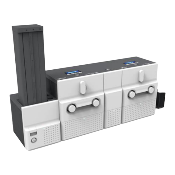
500 cards can continuously be printed, laminated and encoded on various card. SMART-70 consists of 5 different modules (① Input Hopper, ② Printer, ③ Hybrid Flipper, ④ Laminator, ⑤ Output Hopper) that can be configured in various combinations according to different customer requirements. - Page 12 For high-level security, authenticated user can only print, encode and laminate cards by using SMAR-70. Clear Printing SMART-70 can print clear images on card by using IDP’s FINE Technology that can exquisitely control the heat of print head depending on the picture. High Speed ...
- Page 13 Scratch Free SMART-70 can protect a card surface while the card is in SMART-70 for printing and encoding. 500 cards can be loaded in Input Hopper but the cards can be taken out from Input Hopper without scratch by using the patented load distribution structure of IDP.
-
Page 14: Modules
1.2.1 Input Hopper SMART-70 Input Hopper can be loaded up to 500 cards and supply a card at a time. SMART- 70 Input Hopper has the following features. LED Indicator on the front side of Input Hopper displays the status of Input Hopper ... -
Page 15: Figure 2 Front Side Of Input Hopper
Figure 2 Front side of Input Hopper ① Kensington lock Kensington lock is usable. ② Communication port To communicate between SMART-70 modules, please connect to an adjacent module. ③ Serial communication port This port is used when an external device controls Input Hopper. -
Page 16: Printer
1.2.2 Printer SMART-70 Printer is the high-end printer which the IDP’s printing technologies are concentrated. SMART-70 Printer can continuously print 500 cards of color or 3000 cards of mono, and the magnetic stripe and contactless encoding option can be installed. -
Page 17: Figure 4 Front Side Of Printer
Front side of Printer ① Kensington lock Kensington lock is usable. ② Communication port To communicate between SMART-70 modules, please connect to an adjacent module. ③ Serial communication port This port is to communicate with external device except SMART-70 modules. -
Page 18: Figure 6 Control Panel Of Printer
Control panel of Printer consists of 2 lines LCD and 4 buttons. The 4 buttons have the functions as shown in the figure 6. Menu/Cancel Left/Up Right/Down Select/OK Figure 6 Control panel of Printer The menus of the control panel of Printer are as below table. Menu Submenu Description... - Page 19 To set the length of printed image on the card’s Y- >>YScale axis. >>TotalDensity To set the total printing density. >>ColorDensity To set the color density >>BlackDensity To set the resin black density. >>OverlayDensity To set overlay density. To adjust the force for pulling print ribbon during >>RMP+ printing when the residual quantity of print ribbon is in its maximum quantity.
-
Page 20: Hybrid Flipper
1.2.3 Hybrid Flipper SMART-70 Hybrid Flipper can flip over a card for dual sided printing and laminating. And, encoding option and image scanner can be installed into the Hybrid Flipper b option. When the encoder or/and scanner is not installed, the error card bin to collect encoding failed cards is installed by default. -
Page 21: Laminator
Rear side of Hybrid Flipper 1.2.4 Laminator SMART-70 Laminator is the high performance laminator which cards are can be laminated with high quality without warming-up by using the patented technology of the IDP’s “Instant direct heating mechanism”. One roll of the holographic or clear laminating film can laminate 500 cards. -
Page 22: Figure 9 Front Side Of Laminator
Laminator. Conventional laminators must be needed warming-up time before laminating, but SMART-70 Laminator can immediately laminate without having to wait by using IDP’s Instant direct heating mechanism. Instant direct heating mechanism of IDP uses bar-type laminate head to instantly ... -
Page 23: Figure 10 Rear Side Of Laminator
① Kensington lock Kensington lock is usable ② Communication port To communicate between SMART-70 modules, please connect to an adjacent module. ③ Serial communication port This port is to communicate with external device except SMART-70 modules. ④ USB device port When Laminator is used without the Printer, this port is to communicate with PC. - Page 24 Description >>Operating Mode To determine whether Laminator is used as the main control device of SMART-70 system or not. When Laminator is used with Printer, this mode is set to Slave. When Laminator is used alone, this mode is set to Master.
-
Page 25: Output Hopper
>>User Count To display the firmware version of Laminator. >>Factory Count To display the serial number of Laminator. 1.2.5 Output Hopper SMART-70 Output Hopper can stack with 500 cards after printing, laminating and encoding. SMART-70 Output Hopper has the following features. -
Page 26: Figure 12 Front Side Of Output Hopper
LED Indicator on the front side of Output Hopper displays the status of Output Hopper by using the color, so user can intuitionally check the status of Output Hopper. Cards can be conveniently collected by large capacity cartridge which 500 CR80 cards ... -
Page 27: Stacker
Please connect the 24V DC power adaptor provided with Output Hopper. ④ Power switch Turn On/Off. ⑤ Communication port To communicate between SMART-70 modules, please connect to an adjacent module. Figure 13 Rear side of Output Hopper 1.2.6 Stacker If Output Hopper is not needed, 100 cards can be ejected and loaded by using the Stacker provided with Input Hopper. -
Page 28: Installation And Operation
2.1 Hardware installation 2.1.1 PLACEMENT OF MODULES SMART-70 modules need to be placed on a flat table. Order of placing modules from left to right is Input Hopper, Printer, Laminator and Output Hopper. When some module is not required, please remove unnecessary modules from above placing order. For example, when Laminator is not needed, Input Hopper, Printer, Hybrid Flipper and Output Hopper can be placed. -
Page 29: Module Connection
Figure 16 Module fastening 2.1.3 MODULE CONNECTION Please connect the red communication cables provided with the modules to each module. Figure 17 Module connection... -
Page 30: Power Connection
2.1.4 POWER CONNECTION Please connect the 24V DC power adaptors provided with each module to all modules. Printer must be connected to the 24 DC power adaptor provided with Printer. Figure 18 Power connection 2.1.5 PRINT RIBBON AND LAMINATING FILM INSTALLATION A. -
Page 31: Figure 20 Pulling Out Ribbon / Film Cartridge
B. Please pull out ribbon / film cartridge. Figure 20 Pulling out ribbon / film cartridge C. Please mount print ribbon / laminating film by pushing cores into cartridge from the side of cartridge as figure. To properly mount print ribbon or laminating film, please refer to the install guideline on the print ribbon or laminating film box. -
Page 32: Figure 22 Print Ribbon Mounting
When print ribbon is being mounted, please refer to the mounting instruction on the inside of ribbon cartridge as shown as figure. Figure 22 Print ribbon mounting When laminating film is being mounted, please refer to the mounting instruction on the inside of film cartridge as figure. -
Page 33: Figure 24 Print Ribbon / Laminating Film Alignment
D. Please turn the dial on the right side of cartridge to tension print ribbon or laminating film as figure. Figure 24 Print ribbon / laminating film alignment E. Please push ribbon or film cartridge into Printer or Laminator. Figure 25 Ribbon / film cartridge insertion... -
Page 34: Disposable Cleaning Roller Installation
F. Please turn ribbon / film cartridge lock lever to the counterclockwise 90 degrees, so the lever is returned to the vertical. Figure 26 Ribbon / film cartridge locking 2.1.6 DISPOSABLE CLEANING ROLLER INSTALLATION A. Please detach disposable cleaning roller holder from Input Hopper as figure. Figure 27 Detachment of disposable cleaning roller holder... -
Page 35: Figure 28 Used Disposable Cleaning Roller Removal
B. Please remove used disposable cleaning roller from holder. Figure 28 Used disposable cleaning roller removal C. Please mount a new disposable cleaning roller. Figure 29 New disposable cleaning roller mounting... -
Page 36: Figure 30 Removal Of New Disposable Cleaning Roller Protector
D. Please peel off the protector of disposable cleaning roller. Figure 30 Removal of new disposable cleaning roller protector E. Please install disposable cleaning roller holder into Input Hopper as figure. Figure 31 Installation of disposable cleaning roller holder... -
Page 37: Cards Loading
2.1.7 CARDS LOADING A. Please pull up card cartridge while pressing cartridge release button. Figure 32 Card cartridge release from Input Hopper B. Please adjust the gate of card cartridge depending on card thickness by using control lever. Figure 33 Cards thickness adjustment... -
Page 38: Figure 34 Card Cartridge Open
C. Please push the button on card cartridge down and open cartridge cover as figure. Figure 34 Card cartridge open D. Please remove the tape for fixing the weight in card cartridge as figure. Figure 35 Removal of the tape for fixing the weight... -
Page 39: Figure 36 Card Cartridge
E. Please pull up the weight and fix it to the top. Figure 36 Card cartridge’s weight fixing F. Please take care not to touch the surface of cards and load the cards into cartridge. Figure 37 Card loading... -
Page 40: Figure 38 Putting Down The Card Cartridge
G. Please put down the weight on loaded cards as figure. Figure 38 Putting down the card cartridge’s weight H. Please close card cartridge cover and put card cartridge into Input Hopper until click is heard. Figure 39 Loading card cartridge into Input Hopper... -
Page 41: Loading Card Cartridge Into Output Hopper
2.1.8 LOADING CARD CARTRIDGE INTO OUTPUT HOPPER Please put an empty card cartridge into Output Hopper until click is heard. In order to take card cartridge out, please pull up the cartridge while pressing cartridge release button. Figure 40 Loading card cartridge into Output Hopper 2.1.9 POWER ON Please turn on the power switch on the rear side of all modules. -
Page 42: Module Combination Setting
2.1.10 MODULE COMBINATION SETTING Since SMART-70 is operated by the combination of multiple modules, the configuration for multiple modules combination must be set during the first installation of the modules. Printer module acts as master who is responsible to communicate with PC and control other modules, and if Printer module is not connected, Laminator module will act as master. -
Page 43: Figure 44 Adjusted Modules Combination
C. The detected modules combination is shown. Please press the [Select] button indicated by red arrow to save the configuration for detected multiple modules combination. Figure 44 Adjusted modules combination D. The saved multiple modules combination is shown. Figure 45 Saved module combination E. -
Page 44: System Status Check
2.1.11 SYSTEM STATUS CHECK Please check that indicator LEDs on all modules are blue and the status of Printer and Laminator is ready. Figure 47 System status checking 2.1.12 SAMPLE CARD PRINTING A. Please press the “Menu” button indicated by red arrow on Printer. Figure 48 Printer menu... -
Page 45: Figure 49 Printer Menu (System Config)
B. On “System Config” menu, please press the [→] button indicated by red arrow. Figure 49 Printer menu (System Config) C. On “Network Config” menu, please press the [→] button indicated by red arrow. Figure 50 Printer menu (Network Config) D. -
Page 46: Figure 52 Printer Menu (Operation)
E. On “Operation” menu, please press the [Select] button indicated by red arrow. Figure 52 Printer menu (Operation) F. On “Print Sample” menu, please press the [Select] button indicated by red arrow. Figure 53 Printer menu (Print Sample) G. Please wait a while until sample card is printed as figure. Figure 54 Sample Card... -
Page 47: Advanced Hardware Installation
Each module of SMART-70 has a specific ID to communicate with each other because a system of SMART-70 is combined by multiple modules. In that case, if a printer is combined in the system, the printer is a main agent of the communication, and if a printer is not combined in the system, a laminator is a main agent of the communication. - Page 48 The DIP switch of each module is as below Figure SMART-70 Printer doesn’t have the DIP switch, the module ID is automatically set to 0x40 when the Printer is the Master and the module ID is automatically set to 0x41 when the Printer is the Slave.
-
Page 49: System Configuration Of Smart-70
0xMF 2.2.2 System configuration of SMART-70 SMART-70 is basically composed of the combination of Input Hopper(I), Printer(P), Laminator(L), Hybrid Flipper(H) and Output Hopper(O). The encoding option for the magnetic stripe card and contactless smartcard can be installed into the Printer. And, the encoding option for the contact and contactless smartcard and color image scanner can be installed into the Hybrid Flipper. - Page 50 -. First printer P0: Module ID = 0x40, Operation Mode = Master -. Second Printer P1: Module ID = 0x41, Operation Mode = Slave -. Hybrid Flipper H0: Module ID = 0x60 -. Laminator: Module ID = 0x50, Operation Mode = Slave -.
-
Page 51: Cable Connection Of Smart-70
Figure 57 Cable connection of SMART-70 IPHLO When two Printers are combined in a system of SMART-70, the USB Host port of the first Printer should be connected to the USB Device port of the second Printer by using USB cable as Figure 58. -
Page 52: Figure 59 Cable Connection Of Smart-70 Iphlo
Device port of the Hybrid Flipper as Figure 60. Second Hybrid First Printer Flipper Printer Figure 60 Cable connection of SMART-70 IPHPO When SMART-70 system is first installed, the system combination of SMART-70 should be configured by using the LCD control panel. -
Page 53: Software Installation (Windows Vista/7/8/10)
2.3 Software installation (Windows Vista/7/8/10) 2.3.1 Start-up window Please insert the installation CD provided with Printer and choose the language and click “Driver Install” button. *) When you want to install printer driver for USB, please turn off Printer before installation. When you want to install printer driver for network, please turn on Printer. -
Page 54: Figure 65 Printer Driver Installation
2.3.5 Driver Installation STEP 2-2 Please click “Install this driver software anyway” when Windows Security window comes up, Figure 65 Printer driver installation 5 2.3.6 Driver Installation STEP 3-1 Please click “Next” when your Printer is connected via USB. If you want to install the printer driver for network, please select the “TCP/IP Network port”... -
Page 55: Figure 69 Printer Driver Installation
“Close”. Figure 70 Printer driver installation 10 2.3.11 Driver installation check 1 Please open “Devices and Printers” window and check that “IDP SMART-70 Card Printer” is created properly. Figure 71 Printer driver installation 11 2.3.12 Driver installation check 2 Please right click on “IDP SMART-70 Card... -
Page 56: Figure 73 Printer Driver Installation
2.3.13 Driver installation check 3 Please select the “General” tab on “IDP SMART-70 Card Printer” properties and click “Print Test Page”. Figure 73 Printer driver installation 13 2.3.14 Driver installation check 4 When test page is being printed, the widow for checking printing status comes up. -
Page 57: Figure 76 Application Installation 2
2.3.16 Application installation 2 When “Smart Application Install ShieldWizard” window is opened, please click “Next”. Figure 76 Application installation 2 2.3.17 Application installation 3 Please choose “I accept the terms of the license agreement” and click “Next”. Figure 77 Application installation 3 2.3.18 Application installation 4 Please select destination location for application installation and click “Next”... -
Page 58: Driver Configuration
Application installation 6 3. Driver configuration SMART-70 Printer can print cards by selecting various required properties. To adjust printer properties, please open the Devices and Printers window and right click on “IDP SMART-70 Card Printer” and select “Printer Properties”. 3.1 Printing preferences 3.1.1 Printing Preferences... -
Page 59: Figure 82 Layout
Supply: If there is one Input Hopper, please select “Auto”. If there are multiple Input Hoppers, please select the Hopper which will be used. Tray: Please select “CR80” because SMART-70 only supports CR80 cards. Output Tray Output: If there is one Output Hopper select “Auto”. -
Page 60: Figure 84 Printing Settings
Figure 84 Printing settings 3.1.5 Laminating settings This tab will be created only when SMART-70 Laminator module is connected. Do Laminating: To set whether laminate or not. Laminator Side: To set the laminating side of card (top, bottom and both sides). -
Page 61: Advanced Setup
3.1.6 Encoding settings This tab will be created only when SMART-70 Magnetic Encoding option is installed. Do Encoding: To set whether encoding or not. Module: To set whether the internal module (Printer) or the external module (Hybrid Flipper) is used. - Page 62 using “CardPrinter70Setup” utility. Main [-100:100]: To adjust the gamma values of all panels. Yellow [-100:100]: To adjust the gamma value of the yellow panel. Magenta [-100:100]: To adjust the gamma value of the magenta panel. Cyan [-100:100]: To adjust the gamma value of the cyan panel. Black [-100:100]: To adjust the gamma value of the resin black panel.
-
Page 63: Other Settings
Wait Option: This option can set the card’s waiting time at each encoding position when the smart card is encoded without using SDK. One contactless smart card encoder can be installed into SMART-70 Printer. When this option is set and the SDK is not used for encoding, the program which the smart card is recognized and encoded within the specified waiting time must be developed by yourself because the card is only waiting for a specified time at the encoding position. -
Page 64: Ports
3.3.2 Ports The Port tab shows which port is connected to SMART-70 Printer. On Figure, USB001 Virtual printer port is connected because SMART-70 Printer was connected via USB. (Caution! The adjustment on the ports setting by user is not recommended because the port is automatically set.) -
Page 65: Color Management
3.3.4 Color Management The proper color profile for Printer can be set on the Color Management tab. For supporting the optimized color printing, SMART-70 Printer can automatically set the color profile depending on the ribbon type loaded in Printer because the ribbon type is automatically recognized. -
Page 66: Printer Status Check
3.3.6 Printer status check The serial number, ID, driver version, firmware version, ribbon type balance connected modules can be checked on the Service tab. Figure 92 Printer status check... -
Page 67: Smart-70 Utilities
This chapter explains the SMART-70 utilities. 4.1 Printer setting SMART-70 Printer is manufactured and shipped with optimized setting on each one. By the way, printer setting can be adjusted by using CardPrinter70Setup utility included in the Installation CD after disassemble and assemble of printer, replacement of some parts or when the adjustment of printer setting is needed. -
Page 68: Basic Setup
Figure 94 CardPrinter70Setup Start 4.1.2 Basic Setup The basic setup of CardPrinter70Setup shows the firmware version, serial number and etc. of the connected SMART-70 Printer, frequently used setting values (printing position, density and etc.) can be adjusted. ① ② ③... - Page 69 ⑤ To set the printing area on card. Please set it properly to print on an entire card because SMART-70 is a direct thermal card printer. When you click “⑦ Print”, a card is printed as like “④ example”. Please set values properly that all circles of each corner are printed and blank spaces are narrower than 0.5mm on the top and the bottom of a card.
-
Page 70: Figure 96 Color Density
Y Scale: Please set to print all circles in the bottom of card. ⑥ To set printed density. SMART-70 enables to set different density for each color, resin black and overlay. So, proper setting on each density is needed for high quality. Please optimize the quality by adjusting each value. -
Page 71: Figure 97 Resin Black Density
Figure 97 Resin Black density Overlay Density: To set overlay density. Please adjust it until overlay is printed on surface regularly. If it is too strong, it is hazy and marks are appeared. If it is too weak, overlay panel is not printed edge areas. -
Page 72: Advanced Setup
Load Default: To reset setup values to default. After loading default, all setup values must be adjusted again. Load Default is not recommended. Close: To close CardPrinter70Setup. 4.1.3 Advanced Setup Expert setup of SMART-70 Printer can be adjusted on advance setup. If you are unsure, please contact your dealer. ① ②... - Page 73 Change Head Dialog window after click “Change Head”. To show how many cards are issued with SMART-70 Printer. “Total Issue Count” is the number of issued cards after factory shipment. “User Issue Count” is the number of issued cards after replacing print head.
- Page 74 PC. Default is the same number used by all SMART-70. To connect multiple SMART-70 Printers to only one PC via USB, Please set this option to “USE” for using unique serial numbers for each Printer. UART Baud Rate: To set the communication speed (Baud rate) of the external device connected to Printer by serial.
-
Page 75: Printer Test
⑦ Figure 100 ardPrinter70Test ① Select Printer: To select a Printer for test. In the picture. “IDP SMART-70 Card Printer” is the connected Printer’s name, “SMART” is the connected Printer’s ID and “USB006” is the connected port. ② Basic Control: To execute basic functions of Printer (Card In/Out, Print Head Up/Down, etc.). -
Page 76: Printer Selection And Basic Control
⑦ Message: To display messages when this utility is run. 4.2.1 Printer selection and basic control When CardPrinter70Test is run, Printers connected via USB are automatically searched and can be selected by priority. After setting "Allow Network Printer", all Printers connected via USB and network can be selected. -
Page 77: Printer Status
4.2.5 Printer status “Get Temperature” is to get and display the temperature of Thermal Print Head. When the “Realtime Check” is set, the temperature of Thermal Print Head is got and displayed in real time. “Get Status” is to get and display the status of Printer. Status Codes are as below. - Page 78 #define S7PS_S_CLEANWARNING 0x0000000010000000 // Printer Cleaning Warning #define S7PS_S_HAVEPRINTDATA 0x0000000020000000 // Have Printing Data #define S7PS_S_SBSMODE 0x0000000040000000 // SBS Mode #define S7PS_S_TESTMODE 0x0000000080000000 // Test Mode Error Codes are as below. #define S7PS_E_CARDIN 0x0000000100000000 // Card In Error #define S7PS_E_CARDMOVE 0x0000000200000000 // Card Move Error #define S7PS_E_CARDOUT 0x0000000400000000 // Card Out Error...
-
Page 79: Firmware Upgrade
Allow Network Printer: To set that Printers connected via network are displayed in Devices. Printer [ 0 ] / … : To select the modules of SMART-70 system that firmware is upgraded. Version: To displays the current firmware version of selected Printer. -
Page 80: Printer Connection
Modules of SMART-70 System (Printer, Hybrid Flipper) 4.3.2 Module Firmware Upgrade After clicking the tab of the combined modules of SMART-70 System such as “Printer [ 0 ]” or Hybrid Flipper [ 0 ]”, please click “Browse” and search and select the new firmware for the module. -
Page 81: Figure 105 Manual Firmware Upgrade
In case there is some problems in automatic firmware upgrade, please click “Manual Update” to manually upgrade firmware. According to the pop-up window as below figure, firmware can manually be upgraded by clicking “Transfer” after the Printer is manually turned on and off. Figure 105 Manual firmware upgrade... -
Page 82: Troubleshooting
5. Troubleshooting 5.1 Printing quality 5.1.1 Unprinted or wrong colors printed spot The card surface is contaminated by foreign substance : After checking the status of card, please change it to another clean card. The cleaning roller is contaminated : ... -
Page 83: Not Aligned Color Print
5.1.4 Not aligned color print Non-standard or bad cards : Please change cards (ISO CR80 card (54mm x 86mm) must be used). Uneven or bad surface of card : Please change cards. Card feeding or printing roller is contaminated : Please clean the rollers by using cleaning kit ... -
Page 84: Card Supply
5.2 Card supply 5.2.1 Card is not supplied or 2 cards are supplied from Input Hopper Non-standard or bad cards : Please change cards (ISO CR80 card (54mm x 86mm) must be used). Card cartridge is improperly loaded : Please properly load the card cartridge into Input Hopper again. - Page 85 B. Card jam in Input Hopper 2 If card is jammed on the card gate of Input Hopper as Figure, please remove the jammed card by pulling out. Figure 113 Card jam in Input Hopper 2 C. Card jam in Input Hopper 3 If card is not on the card gate of Input Hopper but card cartridge can’t be pulled up, please push in and pull out a new card as...
-
Page 86: Card Jam In Printer
E. Card jam in Input Hopper 5 If card is jammed at the gate of card cartridge Figure, please remove jammed card by pulling out. Figure 116 Card jam in Input Hopper 5 5.3.2 Card jam in Printer A. Card jam in Printer 1 Please turn the ribbon cartridge lock lever to the clockwise 90 degrees as Figure. - Page 87 C. Card jam in Printer 3 If print ribbon is stuck to card or coiled on rollers as Figure, the ribbon cartridge may not be pulled out easily. In this case, please cut the ribbon or slowly pull out the ribbon cartridge while pressing the “”...
-
Page 88: Card Jam In Hybrid Flipper
5.3.3 Card jam in Hybrid Flipper A. Card jam in Hybrid Flipper 1 Please open the cover of Hybrid Flipper by pulling as Figure. Figure 122 Card jam in Hybrid Flipper 1 B. Card jam in Hybrid Flipper 2 Please pull out the error card bin in Hybrid Flipper as Figure. -
Page 89: Card Jam In Laminator
D. Card jam in Hybrid Flipper 4 Please pull out a jammed card as Figure. Figure 125 Card jam in Hybrid Flipper 4 5.3.4 Card jam in Laminator A. Card jam in Laminator 1 Please turn the film cartridge lock lever to the clockwise 90 degrees as Figure. - Page 90 C. Card jam in the Laminator 3 If laminating film is stuck to card or coiled on rollers as Figure, the film cartridge may not be pulled out easily. In this case, please cut the laminating film or slowly pull out the film cartridge while pressing the “”...
-
Page 91: Card Jam In Output Hopper
5.3.5 Card jam in Output Hopper A. Card jam in Output Hopper 1 Please separate Output Hopper as Figure after disconnecting power adaptor and communication cable at rear side. Figure 131 Card jam in Output Hopper 1 B. Card jam in Output Hopper 2 If card is jammed on the card gate of Output Hopper as Figure, please remove the jammed card by pulling out. -
Page 92: Cleaning
D. Card jam in Output Hopper 4 Please pull up card cartridge while pushing the cartridge release button as Figure. Figure 134 Card jam in Output Hopper 4 E. Card jam in Output Hopper 5 If card is jammed at the gate of card cartridge as Figure, please remove the jammed card by pulling out. - Page 93 B. Input Hopper cleaning 2 Please remove the disposable cleaning roller holder in Input Hopper as Figure. Figure 137 Input Hopper cleaning 2 C. Input Hopper cleaning 3 Please pull up the card cartridge while pushing the cartridge release button as Figure.
-
Page 94: Printer Cleaning
5.4.2 Printer cleaning A. Printer cleaning 1 Please turn the ribbon cartridge lock lever to the clockwise 90 degrees as Figure. Figure 140 Printer cleaning 1 B. Printer cleaning 2 Please pull out the ribbon cartridge as Figure. Figure 141 Printer cleaning 2 C. -
Page 95: Hybrid Flipper Cleaning
5.4.3 Hybrid Flipper cleaning A. Hybrid Flipper cleaning 1 Please separate Hybrid Flipper as Figure after disconnecting power adaptor and communication cable at rear side. Figure 143 Hybrid Flipper cleaning 1 B. Hybrid Flipper cleaning 2 Please push a cleaning card into the card gate of Hybrid Flipper until the cleaning card is shown at the other side as Figure and clean rollers by pushing in and pulling out the... -
Page 96: Output Hopper Cleaning
B. Laminator cleaning 2 Please pull out the film cartridge as Figure. Figure 146 Laminator cleaning 2 C. Laminator cleaning 3 Please push a cleaning card in Laminator while pressing the “” button on the control panel of Laminator for 30 seconds as Figure. After cleaning, please press the “”... -
Page 97: Tph (Thermal Print Head) Replacement
B. Output Hopper cleaning 2 Please pull up the card cartridge while pushing the cartridge release button as Figure. Figure 149 Output Hopper cleaning 2 C. Output Hopper cleaning 3 Please push a cleaning card into the card gate of Output Hopper as Figure and clean rollers by pushing in and pulling out the cleaning card slowly and repeatedly. - Page 98 B. TPH replacement 2 Please pull out the ribbon cartridge as Figure. Figure 152 TPH replacement 2 C. TPH replacement 3 Please detach the print head while pressing the print head detaching button as Figure. Figure 153 TPH replacement 3 D.
-
Page 99: Laminator Head Replacement
E. TPH replacement 5 Please disconnect the print head cable from the detached print head as Figure and then connect the print head cable to a new print head. Figure 155 TPH replacement 5 F. TPH replacement 6 Please install the new print head into Printer while turning the ribbon cartridge lock lever to the clockwise 90 degrees as Figure. - Page 100 B. Laminator Head replacement 2 Please pull out the film cartridge as Figure. Figure 158 Laminator Head replacement 2 C. Laminator Head replacement 3 Please detach laminate head while pressing the laminate head detaching button as Figure. Figure 159 Laminator Head replacement 3 D.
- Page 101 F. Laminator Head replacement 6 Please install the new laminate head into Laminator while turning the film cartridge lock lever to the clockwise 90 degrees as Figure. Figure 162 Laminator Head replacement 6...
-
Page 102: Smart-70 Specifications
6. SMART-70 Specifications 6.1 SMART-70 Input Hopper Card Max. 500 cards Capacity Feeding Automatic Size ISO CR80 (54mm x 86mm / 2.12” x 3.38”) Card Thickness 0.38mm (15mil), 1.2mm (47mil) Type PVC, Composite PVC, PET Residual Q’ty Sensor Near Empty & Empty... -
Page 103: Smart-70 Hybrid Flipper
240 (W) x 214 (L) x 305 (H) Dimensions Inch 9.5 (W) x 8.4 (L) x 12 (H) Weight Kg/lbs. Approx. 6.3 kg / 13.9 lbs. 6.3 SMART-70 Hybrid Flipper Communication USB, RS-232C Power Supply Free Voltage (AC100 / 220V, 50~60Hz) System Power Consumption 24V, 2A Temp. -
Page 104: Smart-70 Output Hopper
240 (W) x 214 (L) x 305 (H) Dimensions Inch 9.5 (W) x 8.4 (L) x 12 (H) Weight Kg/lbs. Approx. 6.1 kg / 13.4 lbs. 6.5 SMART-70 Output Hopper Card Max. 500 cards Capacity Feeding Automatic Size ISO CR80 (54mm x 86mm / 2.12” x 3.38”) - Page 105 Revision Record Date Content 2015.1 The first official version was released. The order of chapter 2.2 and 2.3 was changed and the title of chapter 2.2 was modified to Advanced Hardware Installation. The description of the Hybrid Flipper was added. 2016.9 The menu of LCD control panel was modified.
- Page 106 Office: Room 601, 50, Digital-ro 33-gil, Guro-gu, Seoul, 152-742, Korea Tel: +82-2-6099-3700 Fax: +82-2-6099-3717 E-mail: sales@idp-corp.com...
Need help?
Do you have a question about the SMART-70 and is the answer not in the manual?
Questions and answers
whats a mult termination
A multi-termination error for the IDP SMART-70 may occur due to a loose connection between the interface board and the mainboard. In rare cases, a replaced interface board may also be damaged and require replacement again.
This answer is automatically generated