Table of Contents
Advertisement
Advertisement
Table of Contents
Troubleshooting

Related Manuals for idp Smart-30


Summary of Contents for idp Smart-30
-
Page 1: Technical Manual
Color ID Card Printer -Technical Manual 2014-03-24... - Page 2 Trademarks SMART is a trademark and IDP Card Printer is a registered trademark of IDP Corporation. Windows is registered trademarks of Microsoft Corp. All other trademarks or registered trademarks are marks of their respective holders.
-
Page 3: Main Parts
1. Introduction 1.1 Printer Basic Information 1.1.1 Printer Outside Features ◦ 1.1.2 Printer Inside Features ◦ 1.1.3 Ribbon Cartridge Feature ◦ 1.1.4 LED Status and Button Operation ◦ 1.2 Printer Installation and Instructions 1.2.1 Ribbon Installation ◦ 1.2.2 Card Thickness Adjustment ◦... -
Page 4: Parts Replacement
3. Parts Replacement 3.1 Covers 3.1.1 Side Cover Right / Left ◦ 3.1.2 LED-Button Unit ◦ 3.1.3 Stacker Unit ◦ 3.1.4 Front Cover ◦ 3.1.5 Rear Cover ◦ 3.2 Top Cover Unit 3.2.1 Thermal Print Head ◦ 3.2.2 Top Cover ◦... - Page 5 3.4 Drive Unit 3.4.1 Main Drive ◦ 3.4.2 Belt Tension Setting ◦ 3.4.3 Ribbon, Head Down_Up Drive ◦ 3.5 Rollers 3.5.1 Cleaning Roller / Cleaning Roller Fixed ◦ 4 Administration 4.1 Setup 4.1.1 Overview ◦ 4.1.1.1 Function ...
- Page 6 4.1.3.5 Magnetic Stripe 4.1.3.6 Thermal Print Head Replacement 4.1.3.7 Security 4.1.3.8 Etc. 4.2 Test 4.2.1 Overview ◦ 4.2.2 Basic Operation ◦ 4.2.2.1 Select 4.2.2.2 Control 4.2.2.3 Print 4.2.2.4 Allocation 4.2.2.5 Status ...
-
Page 7: Trouble Shooting
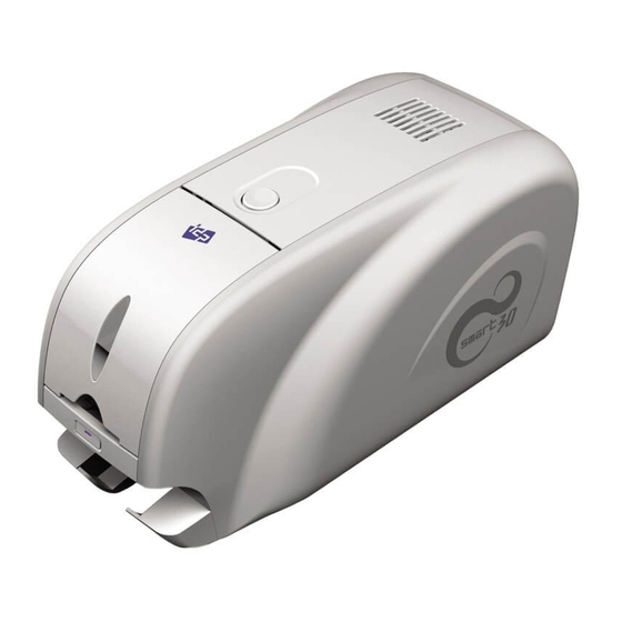
4.2.4 Status ◦ 4.2.4.1 Printer Status Code 4.2.4.2 Printer Error Code 4.3 Firmware 4.3.1 Overview ◦ 4.3.2 Automatic Update ◦ 4.3.3 Manual Update ◦ 5. Trouble Shooting 6.Appendix A. Service Parts List B. Expanded View C. - Page 8 1.1.1 Printer Outside Features This SMART-30 Card Printer takes a power via the adaptor provided with the printer. Using USB port, it communicates with user’s PC. For the user’s convenience, the printer working status can be seen by LED and most of the operations can be controlled by buttons.
- Page 9 1.1 Printer Basic Information Name Function REAR CARD Eject Error Card ⑥ OUTLET POWER SWITCH Printer On/Off ⑥ ⑦ DC POWER Connect DC power (Adapter) ⑧ CONNECTOR Communicate with PC using USB PORT ⑨ USB cable ⑦ ⑧ ⑩ ⑨ ETHERNET PORT Use it after removing the ⑩...
-
Page 10: Printer Inside Features
1.1 Printer Basic Information 1.1.2 Printer Inside Features Smart Printer adopts a semi-permanent cartridge to install a Ribbon. The following shows the internal components and functional features found on your Smart Printer. Name Function ⑤ Stack printed cards and can be STACKER ①... - Page 11 1.1 Printer Basic Information 1.1.3 Ribbon Cartridge Feature Name Function Install a Ribbon and a disposable cleaning roller provided with the Ribbon. (Important! This semi- permanent ribbon cartridge is a ④ ① Ribbon Cartridge component of the printer. Printer does not operate if it is broken or damaged.
- Page 12 1.1 Printer Basic Information 1.1.4 LED Status and Button Operation SMART-30 Printer shows the real-time working status to user using LED and can be controlled by button according to each working status. BUTTON 2014-03-24...
-
Page 13: Printer Driver
1.1 Printer Basic Information Please refer LED status and button operation. SMART-30 shows status messages on watchman that installed with printer driver. Watchman State 상세 설명 Button INIT Error xx Error code is displayed when SMART-30 can’t be initialized . Please press... - Page 14 When there is printing error , the card is not ejected after pressing button. Blink (Check card in Printer) < Cancel > Board Test Mode Printer Test Mode SMART-30 is on test mode that the sensors and motors of printer are tested. Blink Wait 2014-03-24...
- Page 15 1.1 Printer Basic Information Printer Error Code Error Code Details Error Code Details Card In Error Ribbon Search Error Card Move Center Error Ribbon Move Error Card Out Error No Thermal Print Head Installed Card Move Magnetic Error Thermal Print Head Overheat Card Move IC Contact Error No Ribbon Installed Card Move RF Error...
-
Page 16: Ribbon Installation
1.2 Printer Installation and Instructions 1.2 Printer Installations and Instructions 1.2.1 Ribbon Installation Before printing, prepare the related items such as a card, a ribbon and a cleaning roller. In this section, we invite you to know the proper method to install the ribbon and the cleaning roller into the printer. 1. - Page 17 1.2 Printer Installation and Instructions Ribbon Supply Ribbon Take-up Core Core Fig.2-4 Install the ribbon] Fig.2-3 Prepare the ribbon 5. Insert the supply side of the ribbon to 4. Prepare the ribbon before inserting it into no.1 hole and press the opposite(no.2) the ribbon cartridge.
- Page 18 1.2 Printer Installation and Instructions Fig.2-5 Install the cleaning roller Fig.2-6 Peel the protective wrapper 6. Install the disposable cleaning roller to 7. Peel the protective wrapper from the the ribbon cartridge. cleaning roller. To avoid contamination, always hold the cleaning roller.
- Page 19 1.2 Printer Installation and Instructions Fig.2-7 Install the ribbon cartridge Fig.2-8 Close Top Cover 8. Install the ribbon cartridge to the printer 9. Close the top cover until it clicks. after install the ribbon and cleaning roller (If it is not closed, check the installation to the cartridge.
-
Page 20: Card Thickness Adjustment
2. Please check the Hopper Gate is properly adjusted to your card’s thickness. (Caution! If the adjusted card thickness is thinner than your card’s thickness, SMART-30 can’ take a card into printer. If the adjusted card thickness is thicker than your card’s thickness, several cards may be taken into printer at the same time and error occur.) - Page 21 1.2 Printer Installation and Instructions 1.2.3 Cards Load This section shows how to load plastic cards into the Smart Printer. 1. Properly hold cards by sides (Fiz.2-13). ※ Caution! Do not bend the cards and do not touch the surface of the cards. Fig.2-13 Prepare Card 1 2.
- Page 22 1.2 Printer Installation and Instructions 3. Restore the cards stack to its original condition. 4. Place the cards to the hopper and close the hopper cover. Fig.2-16 Cards Load 1 Fig.2-17 Card Load 2 5. In case of one card insert, refer to Fig.2- 18 and Fig.2-19, and insert the card into the hopper.
-
Page 23: Printer Specifications
1.3 Printer Specifications 1.3 Printer Specifications Product Specification SMART-30S SMART-30D Card Types PVC, Polyester Cards with polished PVC finish Printing Method Dye-Sublimation / Resin Thermal / Edge-to-Edge Card Format ISO CR80 (54mm x 86mm) Card Thickness 0.38mm(15mil) ~ 0.76mm(30mil) Resolution 300 dpi Memory 32MB... - Page 24 2.1 Sensors 2.1 Sensors COLOR IN SENSOR CASE OPEN ENCODER SENSOR SENSOR CARD OUT SENSOR COLOR OUT CARD IN HEAD UP-DOWN SENSOR SENSOR SENSOR 2014-03-24...
- Page 25 2.2 Thermal Head and Rollers 2.2 Thermal Head and Rollers Thermal Head MS Roller Cleaning Roller Card Supply Roller IC Roller Printing Roller Cleaning Roller Fixed Card In Roller 2014-03-24...
- Page 26 2.3 Motors 2.3 Motors Ribbon Driver Motor(DC) Main Driver Step Motor Head Up_Down- Hopper Motor(DC) 2014-03-24...
- Page 27 2.4 PCBs 2.4 PCBs Ribbon Front Display Main 2014-03-24...
- Page 28 2.5 Wired Diagram 2.5 Wired Diagram 2014-03-24...
- Page 29 3.1 Covers 3.1 Covers 3.1.1 Side Cover Right / Left 1. Loosen 4 screws on Bottom Frame. 2. Open Front Cover and Top Cover. 3. Grip the bottom part of right/left Side Cover and pivot from upper part of right/left Side Cover. Screw 4.
- Page 30 3.1 Covers 3.1.2 LED-Button Unit 1. Open the Front Cover. Front Cover 2. Broaden the gab between LED-Button unit and Main Frame using screw driver, and then Hook is disassembled. At this time, pull carefully the LED-Button unit to disassemble it. Button Power wire 3.
-
Page 31: Stacker Unit
3.1 Covers 3.1.3 Stacker Unit 1. Hold both sides of the Stacker. 2. Pull out Stacker to separate it from printer. At this time, hold printer to prevent printer from moving. STACKER 3. When install Stacker into printer, push it according the rail of the Stacker and the track of printer. -
Page 32: Front Cover
3.1 Covers 3.1.4 Front Cover 1. Open the Front Cover Front Cover 2. Broaden the gab between Main Frame and Front Cover using screw driver and disassemble Front Cover from Main Frame. Front Cover 2014-03-24... -
Page 33: Rear Cover
3.1 Covers 3.1.5 Rear Cover 1. Rear Cover is assembled to Main Frame by Hook. 2. Unlocked the Hook on both side of the Rear Cover using Screw Driver. Left View Rear Cover Right View 2014-03-24... -
Page 34: Top Cover Unit
3.2 Top Cover Unit 3.2 Top Cover Unit 3.2.1 Thermal Print Head 1. Printer Top Cover Unit consists of Top Top Cover Cover, Top Cover Frame and Thermal Print Unit Head. Thermal 2. Thermal Print Head is fixed by Hinge and Head Hook on Top Cover Frame. -
Page 35: Top Cover
3.2 Top Cover Unit 3.2.2 Top Cover 1. Top Cover is fixed to Top Cover Frame by 3 Screw screws and 2 Hooks. 2. Loosen Screws and unlock Hooks using screw driver, and then disassemble Top Cover from Top Cover Frame. Screw 2014-03-24... -
Page 36: Cooling Fan
3.2 Top Cover Unit 3.2.3 Cooling Fan Cooling FAN 1. Cooling Fan is fixed on Top Cover Frame by 2 Hooks. 2. Unlock Hooks using screw drive and disassemble Cooling Fan. 3. Fan Wire is connected to Connector of Hook Main Board through inside of Printer. - Page 37 3.2 Top Cover Unit 3.2.4 Top Cover Frame 1. Top Cover Frame is assembled to Main Color Frame by Shaft Top Set. Sensor wire 2. Disconnect Thermal Print Head Wire on Main Board. Shaft Top 3. Disconnect Color In Sensor Wire on Thermal Print Head position.
-
Page 38: Main Board
3.3 Main PCBs 3.3 Main PCBs 3.3.1 Main Board 1. Main Board is fixed on Bottom Frame. 2. Bottom Frame is fixed on Main Frame by Main 4 Hooks and 4 Screws, but 4 screws are Frame loosened when Side Cover was Hook disassembled. - Page 39 3.3 Main PCBs 1. Before disassembling Main Board, Left View disconnect cables(T2, T3, T4, T5) on the Right side. ( Be cautious not to make damage on T4 FFC) 2. T5 Wire is connected to LCD-Button unit. On 3.1.2, when disassembling LCD- Button unit, T5 was disconnected form LCD-Button unit, but disconnect T5 Wire to disassemble Main Board.
- Page 40 3.3 Main PCBs 3.3.2 PCB Ribbon RF 1. PCB Ribbon RF is fixed by Hook. 2. Disconnect FFC Wire from PCB Ribbon RF (Be cautious no to make damage on FFC connector) 3. Lift Hook parts by using the screw driver or other device and pull out paralleled to Side Frame direction to disassemble.
-
Page 41: Drive Unit
3.4 Drive Unit 3.4 Drive Unit 3.4.1 Main Drive 1. Main Drive consists of Step Motor and Time Belt. 2. Disassemble Pulley(2), Time Belt(3) and GEAR(7), and then can loosen 3 screws for fixing Step Motor. 3. Step Motor is located inside of Frame. 4. - Page 42 3.3 Drive Unit 3.4.2 BELT Tension Setting Belt-Step Motor 50M2M160 Tension Setting - After put the belt to the pulley, press the pulley as 1.5 ~ 2 kgf to the No.1 arrow direction as Fig.3-1. - In this state, tighten 3 screws to set tension and fix Step Motor.
- Page 43 3.4 Drive Unit 3.4.3 Ribbon, Head Down_Up Drive 1. Ribbon and Head Down_Up Drive is located on the left side of Frame. 2 Ribbon Motor is fixed by 2 screws inside of Frame. (See B.2.1 ASSY S3,LEFT-1, B2.2 ASSY S3,LEFT-2) 3 After disassembling Gear is assembled to Ribbon Motor, enable to disassemble Ribbon Motor.
- Page 44 3.6 Rollers 3.5 Rollers 1. Every Roller is fixed by using Bearing or Bushing on each Main Frame. 2. Disassemble E-Ring on the end of Roller. 3. Disassemble Bearing or Bushing fixed on Frame. While pushing Roller to Frame Right Side. Disassemble Left Side of Printing Ms Roller Roller...
- Page 45 3.6 Rollers 3.5.1 Cleaning Roller / Cleaning Roller Fixed Cleaning 1. While broadening the fixing parts of Roller Cleaning Roller Bracket, pull out Cleaning Roller. 2. Cleaning Roller Bracket is assembled to Cleaning Main Frame by using Hinge. Roller BKT 3.
- Page 46 4.1 Setup 4.1 Setup 4.1.1 Overview 4.1.1.1 Function SMART Card Printer is delivered in optimized state from factory. However it can be set the setup value using CardPrinterSetup Utility provided with CD when the unit is disassemble and reassemble or change of part. The following setup value can be changed using CardPrinterSetup utility.
- Page 47 4.1 Setup 4.1.1.2 Start When start the program there will be displayed the password input window. If input the password, the recorded setup value will be shown and can change that value. The password is saved to SMART Card Printer so even if change to other PC, it need to input the password to change the setup value.
-
Page 48: Basic Setup
4.1 Setup 4.1.2 Setup 4.1.2.1 Basic Setup The most of basic setup can be realized on this window easily. To set more detailed setup, press “>” button for expansion. Printer ID | Printer Name Change Root/User password for SMART Printer Device selection tab Printer information ( Firmware Version, Serial Number) Thermal header information... - Page 49 4.1 Setup Basic Setup Item • Item Explanation Available device list will be displayed. “SMART” is printer ID value. “I&A SMART Card Printer” Device is the printer driver name. Using the printer ID, the printer can be distinguish when you use SDK.
- Page 50 4.1 Setup Basic Setup Item • Item Explanation Black Density Set the image’s total density (Range : -1500 ~ 1000) (See 4.1.3.2) Overlay Density Set the color density (YMC) (Range : -500 ~ 500) (See 4.1.3.2) Example Preview the changed value Print To check the adjusted value.
- Page 51 4.1 Setup 4.1.2.2 Expansion Setup This window can be used to check the printer’s state or change the detailed setup. Menu buttons Usage counter Ribbon sensor control factors Ribbon motor control factors Flipper control factors Magnetic control factors Security factors 2014-03-24...
- Page 52 4.1 Setup Expansion Setup Item • Item Explanation Change Printer ID When use SDK, this ID can be used to distinguish each printer (See 4.1.3.8) Set PC Serial When use PC Authentication, set the PC to print (See 4.1.3.7) Change Head In case of changing thermal print head, set the serial no.
- Page 53 4.1 Setup Expansion Setup Item • Item Explanation Yellow Level Set the yellow level value (Use only in board type 1, 2 ) Magenta Level Set the magnetic level value (Use only in board type 1, 2) Cyan Level Set the cyan level value (Use board type 1, 2) Black Level Set the black level value...
- Page 54 Expansion Setup Item • Item Explanation Board type Set the main board type (Do not change!) Authentication function is applied for security in SMART printer. (See 4.1.3.7) - PC Auth. : Matching SMART printer and PC ( To use this function, press “Set PC Serial” and save the PC authentication information to SMART Printer) Security - Physical key : Set the use of Physical Key in case the printer have customized physical key...
- Page 55 4.1 Setup 4.1.3 Printer Setup Adjustment 4.1.3.1 Printing Location SMART Card Printer is the direct thermal printer and need to some setting to print all over the card surface. In CardPrinterSetup, if press “Print” button, the image like left side will be printed.
-
Page 56: Printing Density
4.1 Setup 4.1.3.2 Printing Density SMART Card Printer is direct thermal printer. Use the thermal heat to print. To print the correct and proper printing, the thermal heat should be different in color printing, resin black printing, overlay printing. So for the best printing image, some adjustment is needed. - Page 57 4.1 Setup Resin Black Printing Density • Resin Black is used to print the black clearly such as the barcode or text. It print the black which extracted by the printer device driver or set as black in Smart Design. The red box in the below figure is printed by resin black.
- Page 58 4.1 Setup Overlay Printing Thickness • Overlay is coating to the surface of card for the protection of printing image. Usually the overlay print all over the card surface but it can be printed in specific area by the device driver or Smart Design software. Overlay is binary type such as black resin, print or not.
-
Page 59: Ribbon Operation
4.1 Setup 4.1.3.3 Ribbon Operation SMART-30 Card Printer’s ribbon movement is variable to make the interference minimized. So to get the stable image quality, set the proper ribbon movement setting. As below graph SMART Card Printer is control the speed of printing and normal movement differently to get the regular speed. - Page 60 4.1 Setup 4.1.3.4 Flipper On SMART-30, flipper can be attached as option. When there is no printing, the Flipper keep the horizontal flat. So the setup of Flipper is to make it the horizontal flat by adjusting its angle. “Rotate Top” and “Rotate Bottom” are the accurate setting when the Flipper is front side or back side to make a horizontal flat with the card movement passage.
-
Page 61: Magnetic Stripe
4.1.3.5 Magnetic Stripe On SMART-30, Magnetic Stripe Encoder can be installed as option. It is encoder module which can read/write to the three tracks to the magnetic stripe card in ISO specification. The magnetic track can be saved as SC, SS, TD, ES, LRC, SC format. - Page 62 4.1 Setup 4.1.3.6 Thermal Print Head Replacement To change the print head, the print head module as below photo should be changed. After change the print head module, its serial no. and register value should be registered. First press “>” button and click “Change Header” and input the serial no.
- Page 63 4.1 Setup 4.1.3.7 Security Password • It need to input the password to change the setup value but if you do not set the password, it need not. When execute CardPrinterSetup program, the password input window will be displayed. If you set the password, it is saved to SMART Card Printer itself so even if you change the PC, the password is needed for that card printer.
- Page 64 4.1 Setup PC Auth. • PC Auth. is a function to operate a SMART printer with specific PC. This is to prevent the access of unauthorized person to print card with another printers. Please read as below. 1. In expansion mode, click “PC Auth.” and “Set Config.” 2.
- Page 65 4.1 Setup Physical Key • Physical Key is the function which is enable to operate SMART printer who have the physical key. It is provided as special option. To use this function, in expansion mode change “Physical Key” to “Use” and press “Set Config.” Physical Key will be activated after SMART printer reboot.
- Page 66 4.1 Setup User Auth. • User Auth. allows using PC for someone who knows User password. To activate this function, please tick ‘User Auth.’ and click ‘Set Config’. After setting User Auth., this function is activated after re-booting ID card printer. In case printer is locked, LCD (or Watchman) displays “Unlock Please”...
- Page 67 4.1 Setup Root Auth. • Root Witness allows using PC for someone (administrator) who knows Root password. To activate this function, please tick ‘Root Auth.’ and click ‘Set Config’. After setting Root Auth., this function is activated after re-booting ID card printer. In case printer is locked, LCD (or Watchman) displays “Unlock Please”...
- Page 68 SBS Only • SMART-30 Printer is provided the printer driver same as other normal printer so it can be used in the application for SMART card printer and other general application. “SBS Only” function can be realized in the application which is developed by our SDK.
- Page 69 4.1 Setup Magnetic Encryption • If the magnetic stripe card is read and write by SMART printer, the magnetic information can be transfer by USB. “Magnetic Encryption” is define the key which is used to encrypt the magnetic information to prevent that information’s hacking between PC and SMART printer.
- Page 70 • To use SMART-30 printer’s SDK, you have to set the printer which you want to use. And in this case you need to get ID to distinguish the printer and it named as Printer ID. Normally we use one PC and one SMART card printer so do not need to concern.
- Page 71 • In SMART-30 Card Printer, even if you change the USB port, you do not need to install the printer driver. This is because their own ID is used in USB communication. Basically every printer have their own ID but considering the general usage circumstance and the convenience of maintenance, it is set as same ID.
- Page 72 4.1 Setup DCL Mode • With DCL mode, you can control card printer without installation of printer driver. It is operated with DCL order in SDK. You can control this mode with DCL order in SDK but printer driver installation pop-up appears whenever card printer is connected.
- Page 73 4.1 Setup Cleaning Warning • SMART printer checks the cleaning time. At that time, Cleaning message is displayed in LCD window. In order not to display the cleaning message, please change ‘Cleaning Warning’ to ‘Off’ and click ‘Set Config’. This function is activated after card printer is re-booted. 2014-03-24...
- Page 74 4.2 Test 4.2 Test 4.2.1 Overview CardPrinterTest is to test the all function of SMART Card Printer. To operate CardPrinterTest program, the device driver should be installed to PC and SMART printer should be connected. Card Printer use the standard printer device driver so it can be printed same as general printer. However if there is encoder, it need to install the driver which the encoder is required.
- Page 75 4.2 Test If execute CardPrinterTest program, the following window will be displayed. It is consist of ① Select, ② Control, ③ Print, ④ Allocation, ⑤ Encoding, ⑥ State, ⑦ Message. ① Select ② Control ③ Print ④ Allocation ⑤ Encoding ⑥...
-
Page 76: Basic Operation
4.2 Test 4.2.2 Basic Operation 4.2.2.1 Selection The section next to “Printer” is for the printer selection. If you execute CardPrinterTest program, you can find out the below thing and show the available printer list, The displayed thing is “Printer ID”. (explained at 4.1 chapter) In below image, it show there is one printer is connected and its printer ID is “SMART”. - Page 77 4.2 Test 4.2.2.2 Control Control is consist of SBS, Card, Move, Rotate, Etc. and it is used to control the printer’s each step. SBS is the operation of SBS (Step-By-Step) mode. The user can control SMART printer using the command. The •...
- Page 78 4.2 Test 4.2.2.3 Print Print can be used to print the designed image which made by Smart Design. To print the card, use “…” and choose CSD file. Press “Open” and select CSD file and press “Print”. When the printer is NORMAL state, if you press “Print”, the data is transfer to SMART printer and print. However in SBS mode, if press “Print”, the data is transfer to SMART printer and waiting the printing command.
- Page 79 4.2 Test 4.2.2.4 Allocation Allocation is used to test the encoding and decoding continually. Set the repeat no. and if press “Batch Start” it repeat the test. In this case if “Include Card In/Out” section is marked, the card in/out operation is also proceed. However if it is not checked, use one card continually..
- Page 80 4.2 Test 4.2.2.5 Status State is to check the printer state. If press “Get Temperature”, it display the thermal head’s temperature. In this case if check “realtime check”, the temperature is checked on time. “Get Status” is to check the printer’s state. It show the ribbon balance, printer condition and error state. If check “realtime”, on time checking.
- Page 81 4.2 Test 4.2.2.6 Message It show the communication detail between CardPrinterTest program and SMART Printer so you can check what kind of command is doing now. 2014-03-24...
- Page 82 4.2 Test 4.2.3 Encoding 4.2.3.1 Magnetic Stripe Magnetic encoding is to test the magnetic stripe card when choose “Magnetic” tap as below. 2014-03-24...
- Page 83 4.2 Test In Magnetic tap, you can do the read/write of the magnetic stripe card. “Read” is the reading of the magnetic stripe card and show the date. In fact “Read” is consist of “Do Read” and “Read All Buffer” but operated at one time. “Do Read” is read the magnetic data in the printer inside. “Read All Buffer”...
- Page 84 4.2 Test When you tick ‘Bit Mode’, display is changed to Bit Mode writing condition. In the ‘Bit Mode’, you can input data with ‘0’ and ‘1’ only. You can set BPI information in the ‘Bit Mode’. BPI range: 210 ~ 40, You can set BPI value: 210, 168, 140, 120, 105, 93, 84, 76, 70, 64, 60, 56, 52, 49, 46, 44, 42, 40 If you set not defined BPI value, above BPI value is set automatically.
- Page 85 4.2 Test If you want to write and read on magnetic in order, you need to do following procedures. Card “IN” → Move “Mag” → Magnetic “Random Fill” → Magnetic “Write” → Magnetic “Read” → Card “OUT” When you select ‘Magnetic’ on the encoding selection tap and click “Batch Start”, magnetic encoding is repeated as below.
- Page 86 4.2 Test 4.2.3.2 Contact Smart Card Contact Smartcard encoding is enable to encode the date to Smartcard when you choose the IC tap. 2014-03-24...
- Page 87 4.2 Test In IC tap, the read/write of Smartcard is possible. “ICH Contact” is the command to contact the head with Smartcard chip. “ICH Discontact” is the dis-contact command. “Init” is the initialization of the installed IC reader. The installed IC reader will be displayed on right down control board.
- Page 88 4.2 Test 4.2.3.3 Contactless (PC/SC) Smart Card Smartcard encoding through PC/SC – The contactless smartcard can be tested through PC/SC protocol after select “RF (PC/SC)” tap of CardPrinterTest program. 2014-03-24...
- Page 89 4.2 Test In RF (PC/SC) tap, the read & write to the contactless smartcard can be done. “Init” is the command to show the installed PC/SC type reader. The available reader will be shown to the left full down control. “Contact” is the command for the connection to the contactless smartcard and “Reset” is the disconnection.
- Page 90 4.2 Test 4.2.4 Status 4.2.4.1 Printer Status Code SMSC_M_CARDIN 0x0000000000000001 // Under Card In SMSC_M_CARDOUT 0x0000000000000002 // Under Card Out SMSC_M_MOVE_PRINT 0x0000000000000004 // Move to Printing Position SMSC_M_MOVE_PRN2ROT 0x0000000000000008 // Move to Flipper from Printer SMSC_M_MOVE_ROT2PRN 0x0000000000000010 // Move to Printer from Flipper SMSC_M_MOVE_IC 0x0000000000000020 // Move to IC Position...
- Page 91 4.2 Test Status codes are changed after Printer firmware 1.00.60 as below. SMSC_S_CLEANWARNING 0x0000000000080000 // Need to cleaning State (After f/w 1.00.60) SMSC_S_THUP 0x0000000000080000 // Thermal Print Head Up state (Before f/w 1.00.60) SMSC_S_EQUIPLAMINATOR 0x0000000000400000 // Laminator is installed (After f/w 1.00.60) SMSC_S_ROTATORTOP 0x0000000000400000 // Card Front Side is up at Rotator (Before f/w 1.00.60)
- Page 92 4.2 Test 4.2.4.2 Printer Error Code SMSC_F_CARDIN 0x0000000100000000 // Card In Fail SMSC_F_MOVETOPRINT 0x0000000200000000 // Moving to Printing Position is Fail SMSC_F_CARDOUT 0x0000000400000000 // Card Out is Fail SMSC_F_MOVETOMAG 0x0000000800000000 // Moving to Magnetic Position is Fail SMSC_F_MOVETOIC 0x0000001000000000 // Moving to IC Position is Fail SMSC_F_MOVETORF 0x0000002000000000 // Moving to RF Position is Fail...
- Page 93 4.3 Firmware 4.3 Firmware 4.3.1 Overview CardPrinterFirmware is the software for changing the firmware of SMART printer. The firmware of SMART printer is the operating software for the processor of SMART printer. If new function is added or there is other reason, it will be provided by web-site or distributor.
- Page 94 4.3 Firmware 4.3.2 Automatic Update Printer Update is the same as Laminator Update. The upgrade procedure is as follows. 1.Check the current printer’s firmware version. 2.Press “Browse” button and select the firmware you want to install. 3.Press “Update” button and update. 4.Click “OK”...
- Page 95 4.3 Firmware 4.3.5 Manual Update Manual update procedure is as follows. 1.Check the printer’s firmware version. 2.Press “Browse” button and select the firmware you want to install. 3.If press “Manual Update”, “Manual Update Instruction” window will be displayed. 4.Follow “Manual Update Instruction”. 5.If press “Transfer”...
-
Page 96: General Operation
5.1 General Operation 5.1 General Operation Symptom Countermeasures Related Parts Open the top cover and pull out the ribbon cartridge. Connect the ribbon When the ribbon is torn and install again. If the problem is occurred too often, refer to the below countermeasures. - Page 97 5.1 General Operation Symptom Countermeasures Related Parts When Color In/Out Sensor have some problem, replace the sensors. Change the Color In Sensor - Manual 3.2.4 630026(SENSOR COLOR OUT2 BD,SMART,0.3) Color In Sensor or Color Out Sensor is bad 630024(SENSOR COLOR IN BD,SMART,0.4) Change the Color Out Sensor 630033(SENSOR ENCODER2...
- Page 98 5.1 General Operation Symptom Countermeasures Related Parts Printer is not working even if the printing data is Refer to the below countermeasures. sent or the printer is not booting. Printer power is off. Power on the printer. Using another DC adaptor. Check DC adaptor and use our adaptor which supplied with the printer.
- Page 99 5.2 Card Moving 5.2 Card Moving Symptom Countermeasures Related Parts Press the left key on the front side of printer to replay. If it is Card is not inserted from the hopper not moving and the problem is happen so often, please refer to the below countermeasures.
- Page 100 5.2 Card Moving Symptom Countermeasures Related Parts Press the left key on the front side of printer to replay. If it not When there is an error during card movement moving and the problem is happen so often, please refer to the below countermeasures.
- Page 101 5.3 Printer Noise 5.3 Printer Noise Symptom Countermeasures Related Parts When print, there is a big bang sound at the end of Card side is not in specification or the setting is not proper. printing. Refer to the manual 4.1.3.1 and reset or change the card. There is ribbon gear noise as the printer is not properly Ribbon is winding on the gear side of ribbon core so it is get wind the ribbon.
-
Page 102: Printing Quality
5.4 Printing Quality 5.4 Printing Quality Symptom Countermeasures Related Parts Some parts of a card are not printed or printed in It can be happened if the printer is not used for a long time or not clean different colors card is used. - Page 103 5.4 Printing Quality Symptom Countermeasures Related Parts Pictures are not smooth or blurred It can be happened when the printing density is set too low. Increase the printing density value and if the problem not solved, refer to the below countermeasures.
- Page 104 5.4 Printing Quality Symptom Countermeasures Related Parts If the color matching is wrong It might be the problem of printing position. The image starting position should be 0.5mm. If the problem is not solved, refer to the below countermeasures. ※ Reset the position as manual 4.1.3.1. Clean the surface of rollers which described as follows.
- Page 105 5.4 Printing Quality Symptom Countermeasures Related Parts When the side part of card is not printed It might be occurred when the print density is set too low. Increase the printer printing density and if the problem is not solved, refer to the below countermeasures. ※...
- Page 106 5.4 Printing Quality Symptom Related Parts Countermeasures When the following problem is occurred If print too dark image, this kind of problem might be happened. Refer to the manual 4.1.3.2 and adjust the printing density. If the problem is not cleared, using plus type driver and adjusting it until the problem is removed.
- Page 107 5.5 Magnetic Stripe Read/Write 5.5 Magnetic Stripe Read/Write Symptom Countermeasures Related Parts In case there is the magnetic stripe encoding Press the left button of front LCD to replay. read/write error In case the magnetic stripe read/write error is Refer to the below countermeasures. occurred too often Magnetic stripe date is not transmitted or wrong Check the program and driver’s version and the matching between...
- Page 108 5.6 Flipper 5.6 Flipper Symptom Countermeasures Related Parts In case there is no flipper operation sound when the printer is initialized or the Flipper is not recognized flipper is not recognized, check the flipper cable connection state. Refer to the C.2 and check it.
- Page 109 A. Service Parts List A. Service Parts List Item BOARD SENSOR CABLE CASE MOTOR BELT ROLLER A.10 OPTION 2014-03-24...
- Page 110 A.1 BOARD A.1 BOARD CODE NO. ITEM DESCRIPTION PHOTO PAGE 3.3.1 630083 MAIN BOARD MAIN BD,SMART,0.57 B.1.4 B.2.10 3.3.2 630020 RIBBON RF BOARD RIBBON F BD,SMART,2.0 B.2.4 630050 USB HUB BOARD 1 USB HUB BD,SMART,0.1 630096 MS BOARD MS MAIN BD,SMART,0.5 630104 INTERNAL RF BOARD IN_RF_GENDER_30 BD,SMART30,0.1...
- Page 111 A.2 SENSOR A.2 SENSOR CODE NO. ITEM DESCRIPTION PHOTO PAGE 630019 HEAD UP-DOWN SENSOR SENSOR DETECTOR BD,SMART,0.4 B.2.1 630101 CARD IN_OUT SENSOR SEN_POS_30 BD,SMART30,0.2 B.2.3 630024 COLOR IN SENSOR SENSOR COLOR IN BD,SMART,0.4 B.1.1.1 630026 COLOR OUT SENSOR SENSOR COLOR OUT2 BD,SMART,0.3 B.2.7 630033 ENCODER SENSOR...
- Page 112 A.3 CABLE A.3 CABLE CODE NO. ITEM DESCRIPTION PHOTO PAGE 611075 IO CABLE R WIRE,I/O_30 RIGHT,20P,420mm B.1.4 611076 IO CABLE L WIRE,I/O_30 LEFT,20P,230mm B.1.4 611077 LED CABLE WIRE,LED_30 SW,5P,220mm B.1.4 610132 HEAD CABLE WIRE,THERMAL HEAD,26P,370MM B.1.4 611078 IC SENSOR CABLE WIRE,IC_30 MOT SEN,6P,210mm 610137 RF IN CABLE...
- Page 113 A.4 FFC A.4 FFC CODE NO. ITEM DESCRIPTION PHOTO PAGE 611079 RIBBON RF FFC CABLE,240mm,16P,0.5mm,2896 C-type 3.3.2 610146 MS FFC FFC CABLE,170mm,16P,0.5mm,2896 C-type 611080 IC FFC FFC CABLE,37mm,8P,1mm,2896 C-Type 2014-03-24...
- Page 114 A.5 CASE A.5 CASE CODE NO. ITEM DESCRIPTION PHOTO PAGE 611042 TOP COVER COVER S3,TOP B.2.11 611034 TOP CASE OPEN BUTTON BUTTON S3,TOP B.1.1.3 611089 HOPPER COVER ASSY S3,FRONT_COVER B.2.11 611040 SIDE COVER R COVER S3,SIDE_R B.2.12 611039 SIDE COVER L COVER S3,SIDE_L B.2.12 611035...
- Page 115 A.5 CASE CODE NO. ITEM DESCRIPTION PHOTO PAGE 610079 RIBBON CARTRIDGE CASE SS,CARTRIDGE B.2.13 B.1.13 610490 FOOT ASSY SS,FOOT_RUBBER_LA0621 B.2.10 2014-03-24...
- Page 116 A.6 MOTOR A.6 MOTOR CODE NO. ITEM DESCRIPTION PHOTO PAGE 630058 RIBBON MOTOR RIBBON MOTOR BD,SMART,0.4 B.2.1 630097 HEAD DOWN/UP MOTOR HEAD UD MOTOR_30 BD,SMART30,0.1 B.2.1 B.1.7 640264 PRINT STEP MOTOR ASSY S3,STEP_MOTOR B.2.4 2014-03-24...
- Page 117 A.7 BELT A.7 BELT CODE NO. ITEM DESCRIPTION PHOTO PAGE 611010 BELT S3,50S2M160 STEP BELT B.2.9 610913 BELT SS,PI39.7X3.5_SILICONE RIBBON FEEDING BELT B.2.8 2014-03-24...
- Page 118 A.8 ROLLER A.8 ROLLER CODE NO. ITEM DESCRIPTION PHOTO PAGE 611063 FIX ROLLER ROLLER S3,CLEANING_FIX B.2.5 611067 MS ROLLER ROLLER S3,MS B.2.5 3.5.1 610920 CLEANING ROLLER ROLLER SS,CLEANING,1.1 B.1.8 B.2.7 611095 PRINTING ROLLER ASSY S3,ROLLER PRINTING B.2.5 611066 IC ROLLER ROLLER S3,IC B.2.5 611064...
- Page 119 A.9 ETC A.9 ETC CODE NO. ITEM DESCRIPTION PHOTO PAGE 610344 FAN,AD0524HB-G70(T)/LF B.1.1.3 B.1.3 651089 PRINT HEAD ASS'Y SP S3 PRINT_HEAD_ASSY_KPE B.2.13 B.1.11 640266 DISPLAY PANEL ASSY S3,FRONT_DISPLAY B.2.10 630105 MS HEAD MS_TG313RWVPH_30 BD,SMART30,0.1 1.1.1 610697 ADAPTOR ADAPTOR,STD-2427P,24V/2.7A,- B.2.15 2014-03-24...
- Page 120 A.10 OPTION A.10 OPTION CODE NO. ITEM DESCRIPTION PHOTO PAGE 651084 MAGNETIC ENCODER SP S3 MAGNETIC_ENCODER 651107 FLIPPER SP S3 FLIPPER 651079 INTERNAL SMART CARD ENCODER SP S3 INTERNAL_SMART_CARD_ENCODER INTERNAL CONTACTLESSSMART 651081 SP S3 INTERNAL_CONTACTLESS_CARD_ENCODER1 CARD ENCODER 650967 ETHERNET HUB SP SS NETWORK_HUB 2014-03-24...
- Page 121 B. Expanded View B. Expanded View B.1 PHANTOM PARTS EXPANDED VIEW B.2 MAIN PARTS EXPANDED VIEW B.3 FLIPPER OPTION PARTS EXPANDED VIEW 2014-03-24...
- Page 122 B.1 PHANTOM PARTS EXPANDED VIEW B.1 Phantom Parts Expanded View B.1.1 ASSY S3,TOP_COVER B.1.1.1 ASSY S3,TOP_COVER 2014-03-24...
- Page 123 B.1 Phantom Parts Expanded View B.1.1.2 ASSY S3,TOP_COVER 2014-03-24...
- Page 124 B.1 Phantom Parts Expanded View B.1.1.3 ASSY S3,TOP_COVER 2014-03-24...
- Page 125 B.1 Phantom Parts Expanded View ◦ B.1.2 ASSY S3,TENSION_IDLER_ROLLER 2014-03-24...
- Page 126 B.1 Phantom Parts Expanded View B.1.3 ASSY S3,PRINT_HEAD_KPE 2014-03-24...
- Page 127 B.1 Phantom Parts Expanded View B.1.4 ASSY S3,MAIN_BOTTOM 2014-03-24...
- Page 128 B.1 Phantom Parts Expanded View B.1.5 ASSY S3,RIBBON_IDLER 2014-03-24...
- Page 129 B.1 Phantom Parts Expanded View B.1.6 ASSY S3,HEAD_DOWN_UP_IDLER 2014-03-24...
- Page 130 B.1 Phantom Parts Expanded View B.1.7 ASSY S3,STEP_MOTOR 2014-03-24...
- Page 131 B.1 Phantom Parts Expanded View B.1.8 ASSY S3,CLEANING 2014-03-24...
- Page 132 B.1 Phantom Parts Expanded View B.1.9 ASSY S3,HOPPER_GATE 2014-03-24...
- Page 133 B.1 Phantom Parts Expanded View B.1.10 ASSY S3,GEAR_MIRROR 2014-03-24...
- Page 134 B.1 Phantom Parts Expanded View ◦ B.1.11 ASSY S3,FRONT_DISPLAY 2014-03-24...
- Page 135 B.1 Phantom Parts Expanded View B.1.12 ASSY S3,FRONT_COVER 2014-03-24...
- Page 136 B.1 Phantom Parts Expanded View B.1.13 ASSY SS,FOOT_RUBBER_LA0621 2014-03-24...
- Page 137 B.2 MAIN PARTS EXPANDED VIEW B.2 Main Parts Expanded View B.2.1 ASSY S3,LEFT-1 2014-03-24...
- Page 138 B.2 Main Parts Expanded View B.2.2 ASSY S3,LEFT-2 2014-03-24...
- Page 139 B.2 Main Parts Expanded View B.2.3 ASSY S3,RIGHT-1 2014-03-24...
- Page 140 B.2 Main Parts Expanded View B.2.4 ASSY S3,RIGHT-2 2014-03-24...
- Page 141 B.2 Main Parts Expanded View B.2.5 ASSY S3,ROLLER & BUSH 2014-03-24...
- Page 142 B.2 Main Parts Expanded View B.2.6 ASSY S3,TENSION_ROLLER 2014-03-24...
- Page 143 B.2 Main Parts Expanded View B.2.7 ASSY S3,TOP_COVER & CLEANING_ROLLER 2014-03-24...
- Page 144 B.2 Main Parts Expanded View B.2.7.1 BRUSH SS,SUS_BRUSH,10mm 1. Stick BRUSH SS,SUS_BRUSH,10mm to COVER SS,COLOR_SEARCH,1.0 on the position as Fig.1. 2. Bend BRUSH SS,SUS_BRUSH,10mm more than 90 degree as Fig.2. 3. Assemble COVER with BRUSH into Printer as Fig.3. SUS_BRUSH 붙이는 부위 [611013] BRACKET S3,COLOR_SEARCH_COVER <Fig.2>...
- Page 145 B.2 Main Parts Expanded View B.2.8 ASSY S3,RIBBON & HEAD_D/U & HOPPER GRAR 2014-03-24...
- Page 146 B.2 Main Parts Expanded View B.2.9 ASSY S3,MAIN_PULLEY_GEAR & BELT 2014-03-24...
- Page 147 B.2 Main Parts Expanded View B.2.10 ASSY S3,MAIN_BOTTOM & FRONT_DISPLAY 2014-03-24...
- Page 148 B.2 Main Parts Expanded View B.2.11 ASSY S3,TOP & FRONT & BACK COVER 2014-03-24...
- Page 149 B.2 Main Parts Expanded View B.2.12 ASSY S3,SIDE_COVER & STACKER 2014-03-24...
- Page 150 B.2 Main Parts Expanded View B.2.13 ASSY S3, CARTRIDGE & HEAD 2014-03-24...
- Page 151 B.2 Main Parts Expanded View B.2.14 ASSY S3,SMART-30_1.0_STD_MD 2014-03-24...
- Page 152 B.2 Main Parts Expanded View B.2.15 SMART30_PACKING 2014-03-24...
- Page 153 B.2 Main Parts Expanded View B.2.16.1 Ground Wiring 1. Assemble Ground Wire (611164, WIRE,EARTH_LINK,1P,290mm) on the Left Main Frame. 2. Fig.1 is the side of Left Main Frame before tightening screws on BRACKET S3,COLOR_SEARCH_COVER. 3. Insert screw into O-Ring as Fig.2-1 and tighten screw on BRACKET S3,COLOR_SEARCH_COVER as FIg2-2.
- Page 154 B.2 Main Parts Expanded View B.2.16.2 Ground Wiring 4. Insert screw into BRACKET S3,COLOR_SEARCH_COVER TIE through SS,RETAINER_COIL_RB2 as Fig.3 and tighten screw. Assemble position of TIE SS,RETAINER_COIL_RB2 <Fig.3> <Fig.4> 5. Fix ground wire by using TIE SS,RETAINER_COIL_RB2 as Fig.4. • At this time, stick TIE SS,RETAINER_COIL_RB2 and Ground Wire to FRAME S3,MAIN_BODY_L.
- Page 155 B.2 Main Parts Expanded View B.2.16.3 Ground Wiring 6. Insert Ground Wire into printer after hanging Ground Wire on Wire Holder Fig.6. 7. O-ring of Ground Wire is Fig.7-1. To assemble it to main board, fold O-ring as Fig.7-1. Wire Holder <Fig.7-1>...
- Page 156 B.3 FLIPPER OPTION PARTS EXPANDED VIEW B.3 FLIPPER Option Parts Expanded View B.3.1.1 ASSY S3,GUIDE_FLIPPER_MAIN 2014-03-24...
- Page 157 B.3 FLIPPER Option Parts Expanded View B.3.1.2 ASSY S3,GUIDE_FLIPPER_MAIN 2014-03-24...
- Page 158 B.3 FLIPPER Option Parts Expanded View B.3.1.3 ASSY S3,GUIDE_FLIPPER_MAIN 2014-03-24...
- Page 159 B.3 FLIPPER Option Parts Expanded View B.3.2 ASSY S3,FLIPPER_MAIN_L 2014-03-24...
- Page 160 B.3 FLIPPER Option Parts Expanded View B.3.3 ASSY S3,FLIPPER_MAIN_R 2014-03-24...
- Page 161 B.3 FLIPPER Option Parts Expanded View B.3.4.1 ASSY S3,FLIPPER_MAIN 2014-03-24...
- Page 162 B.3 FLIPPER Option Parts Expanded View B.3.4.2 ASSY S3,FLIPPER_MAIN 2014-03-24...
- Page 163 B.3 FLIPPER Option Parts Expanded View B.3.5.1 ASSY S3D,FLIPPER 2014-03-24...
- Page 164 B.3 FLIPPER Option Parts Expanded View B.3.5.2 ASSY S3D,FLIPPER 2014-03-24...
- Page 165 B.3 FLIPPER Option Parts Expanded View B.3.6 ASSY S3D,SMART-30_DUAL_STD_MD 2014-03-24...
- Page 166 B.3 FLIPPER Option Parts Expanded View B.3.7 ASSY S3D,SMART-30_DUAL_STD_MD 2014-03-24...
- Page 167 C. OPTIONs C. OPTION Unit Placement & Wiring OPTION IA. CODE NAME MS Option 651084 SP S3 MAGNETIC_ENCODER FLIPPER Option 651107 SP S3 FLIPPER CONTACT ENCODER 651079 SP S3 INTERNAL_SMART_CARD_ENCODER CONTACTLESS ENCODER 650423 SP S3 INTERNAL_CONTACTLESS_CARD_ENCODER1 USB HUB ASSY 650415 USB HUB BD,SMART,0.1 ETHERNET Option 650967...
- Page 168 C.1 MS Option C.1 MS Option 주요 부품 IA Code NAME Q’ty 610020 O_RING SS,PI1.7/1 610116 HOLDER SS,MS_HEAD_SPRING_SET 610355 SCREW SS,M3X6,SAM 610366 SCREW SS,M3X10,S 610374 WASHER SS,M3_SPRING 610375 NUT SS,M3X2.4 610430 SCREW SS,M3X6,HEX 610507 SPRING SS,MS_TENSION 630096 MS MAIN BD,SMART,0.5 630105 MS_TG313RWVPH_30 BD,SMART30,0.1 610146...
- Page 169 C.1 MS Option MS HEAD ASSY Assembly IA. CODE NAME Q'TY 1. MS Encoder consists of MS MAIN 610020 O_RING SS,PI1.7/1 BD,SMART,0.5 and MS_TG313RWVPH_30 610116 HOLDER SS,MS_HEAD_SPRING_SET BD,SMART30,0.1(MS Encoding Head). 610366 SCREW SS,M3X10,S 2. To install MS Encoder, disassemble Bottom Frame from printer (See 3.3.1).
- Page 170 C.1 MS Option MS HEAD ASSY Assembly IA. CODE NAME Q'TY 630096 MS MAIN BD,SMART,0.5 610355 SCREW SS,M3X6,SAM 610430 SCREW SS,M3X6,HEX 610374 WASHER SS,M3_SPRING 610375 NUT SS,M3X2.4 610146 FFC CABLE,170mm,16P,0.5mm,2896 c-type 2014-03-24...
- Page 171 C.1 MS Option MS Wiring M / B 4. Assemble MS MAIN BD,SMART,0.5 to Printer Main Board on disassembled Bottom Frame. MS Board 5. Fold FFC Wire included in box as figure Supporter Hub Board and connect it to MS MAIN BD,SMART,0.5 Hub Board Supporter MS Board...
- Page 172 C.2 Flipper Option C.2 Flipper Option Main Parts IA Code NAME Q’ty 640288 ASSY S3,FLIPPER_OPTION 610366 SCREW SS,M3X10,S_W 610877 SCREW SS,M3X8,S 2014-03-24...
- Page 173 C.2 Flipper Option FLIPPER Assembly 1. To assemble Flipper Unit, disassemble IA. CODE NAME Q'TY Side Cover Right / Left and Rear Cover 640254 ASSY S3,SMART-30_1.0_STD_MD from Printer (See 3.1 Covers) 640288 ASSY S3,FLIPPER_OPTION 2. Insert the lower bumps of Flipper Unit to 610148 FFC CABLE,350mm,30P,0.5mm,2896 c-type the groove of the Main Frame of Printer...
- Page 174 C.2 Flipper Option FLIPPER Wiring 1. Flipper Unit is connected to Printer Main Board using FFC Wire (- Red Line). 2. Assemble FFC Wire and hold it following to Wire Holders consist of Grooves and Hooks on Main Frame. 3.
- Page 175 C.2 Flipper Option CASE Assembly 1. After assembling Flipper Unit, assemble IA. CODE NAME Q'TY Cover Side Left/Right (See 3.1.1 Side 640254 ASSY S3,SMART-30_1.0_STD_MD Cover Right / Left) 611175 COVER S3,FLIPPER_MAIN 2. Push Cover Flipper Main from the behind 610887 SCREW SS,M3X8,S of Printer.
- Page 176 C.3 IC Option C.3 CONTACT ENCODER Option Main Parts IA Code NAME Q’ty 640269 ASSY S3,IC_OPTION_GEMPLUS 610366 SCREW SS,M3X10,S,_W 611080 FFC CABLE,37mm,8P,1mm,2896 C-TYPE 611078 WIRE,IC_30 MOT SEN,6P,210mm 2014-03-24...
- Page 177 CONTACT ENCODER Option Assembly 1. Disassemble SIDE and REAR COVER of Printer. IA. CODE NAME Q'TY 2. Assemble No.4(BOTTOM SS,IC_SET) on SMART-30. 640254 ASSY S3,SMART-30,10.0_STD_MD 3. Insert cables as Fig.1. 640269 ASSY S3,IC_OPTION_GEMPLUS 4. Push Contact Encoder to stopper and tighten...
- Page 178 C.3 IC Option CONTACT ENCODER Option Wiring 1. Connect cable from Main Frame R to Main 2. Arrange cable from Main Frame L to the Board as figure(RED LINE). beside of Print Head Cable as Figure(GREEN LINE) 3. Connect the cable to USB HUB PORT 2. 2014-03-24...
- Page 179 C.4 Internal RF Option C.4 CONTACTLESS ENCODER Option Main Parts IA Code NAME Q’ty 630104 IN_RF_GENDER_30 BD,SMART30,0.1 610137 WIRE,OMNIKEY RF IN USB,170mm,USB1.0 2014-03-24...
- Page 180 C.4 Internal RF Option CONTACTLESS ENCODER Option Assembly 1. Disassemble SIDE COVER L and R (See 3.1.1). 2. Disassemble REAR COVER (See 3.1.5). 2014-03-24...
- Page 181 C.4 Internal RF Option CONTACTLESS ENCODER Option Assembly IA. CODE NAME Q'TY 1. Push Contactless Encoder following to the grooves of 630104 IN_GENDER_30 BD,SMART30,0.1 Main Frame as figures. 2. Push Contactless Encoder until can’t push it any more. 2014-03-24...
- Page 182 C.4 Internal RF Option CONTACTLESS ENCODER Option Wiring 1. Wire of Contactless Encoder is located on the upper side of USB Hub on Printer Main Board. Connect the wire of Contactless Encoder to USB port Orange Line). 2. At this time, the wire of Contactless Encoder must be connected to PORT2 PORT3.
- Page 183 C.5 USB HUB ASSY C.5 USB HUB ASSY Main Parts IA Code NAME Q’ty 610355 SCREW SS,M3X6,SAM 610375 NUT SS,M3X2.4 610430 SCREW SS,M3X6,HEX 630050 USB HUB BD,SMART,0.1 2014-03-24...
- Page 184 C.5 USB HUB ASSY USB HUB ASSY Assembly 1. For assembling Encoder Option, assemble USB HUB to Printer Min Board. IA. CODE NAME Q'TY 2. Assemble the Bolt for supporting USB 610355 SCREW SS,M3X6,SAM Hub Board on Printer Main Board. 610375 NUT SS,M3X2.4 3.
- Page 185 C.6 Ethernet Option C.6 ETHERNET Option Main Parts IA Code NAME Q’ty 610355 SCREW SS,M3X6,SAM 610375 NUT SS,M3X2.4 610673 SCREW SS,M3X13,HEX 630070 NETWORK HUB EDDY-CPU V2.5-ASSY 610374 WASHER SS,M3_SPRING 2014-03-24...
- Page 186 C.6 Ethernet Option ETHERNET OPTION Assembly IA. CODE NAME Q'TY 1. Assemble HEX SCREW on Printer Main Board using 630070 NETWORK HUB EDDY-CPU V2.5-ASSY washers and nut. 610355 SCREW SS,M3x6,SAM 2. Fix Printer Main Board to Bottom Frame using existing 610673 SCREW SS,M3x13,HEX M3 Screw.
- Page 187 C.6 Ethernet Option ETHERNET OPTION Wiring 1. If use only Ethernet Option, do not need another wiring. 2. If you need another option after installing of Ethernet, please refer to description of connecting relation as photo below. (reference: instruction of circuit) 3.
Need help?
Do you have a question about the Smart-30 and is the answer not in the manual?
Questions and answers