Table of Contents
Advertisement
Available languages
Available languages
Quick Links
Advertisement
Chapters
Table of Contents

Related Manuals for AEMC 6609


Summary of Contents for AEMC 6609
- Page 1 PROBADOR DE FASE & ROTACIÓN DE MOTOR 600V CAT III 300V CAT IV L1/A L3/C L2/B TEST PHASE & MOTOR ROTATION MODEL 6609 E N G L I S H User Manual Manual de instrucciones E S PA Ñ O L...
- Page 3 The recommended verification interval for this instrument is 12 months and begins on the date of receipt by the customer. For verification, please use our calibration services. Refer to our repair and calibration section at www.aemc.com. Serial #: ____________________________ Catalog #: 2121.11 Model #: 6609...
-
Page 4: Table Of Contents
Table of Contents INTRODUCTION ............3 1.1 International Electrical Symbols ........4 1.2 Definition of Measurement Categories ......4 1.3 Receiving Your Shipment ..........5 1.4 Ordering Information ............5 1.4.1 Accessories and Replacement Parts .....5 PRODUCT FEATURES ..........6 2.1 Description ..............6 2.2 Control Features.............7 SPECIFICATIONS ............8 OPERATION ..............9 4.1 Phase Rotation Direction..........9 4.2 Indication of Direction of the Rotating Field, or Direction of Rotation without Connecting Test Leads ...10 4.3 Determining the Direction of Connection of... -
Page 5: Introduction
• This instrument can be used on CAT III electrical circuits not exceeding 600V with respect to earth. It must be used indoors, in an environment not exceeding pollution level 2, at an altitude of not more than 2000m. The instrument can therefore be used in complete safety on 400V three-phase networks in an industrial environment. • For safety reasons, you must use only measurement leads having a voltage rating and category at least equal to those of the instru- ment and compliant with standard IEC 61010-031. • Do not use if the cover of the battery compartment is missing or if the housing is damaged or not correctly closed. • Do not place your fingers near unused terminals. • If the instrument is used other than as specified in this manual, the protection provided by the instrument may be impaired. • Do not use this instrument if it seems to be damaged. • Check the integrity of the insulation of the leads and of the hous- ing. Replace damaged leads. • Be prudent when working in the presence of voltages exceeding or 33Vrms and 46.7Vpp; such voltages can cause a risk of electrocution. The use of individual protections is recommended in some cases. • Always keep your hands behind the physical guards of the probe tips or alligator clips. • Always disconnect all leads from the measurement and from the instrument before opening the housing. Phase & Motor Rotation Tester Model 6609... -
Page 6: International Electrical Symbols
1.2 Definition of Measurement Categories CAT I: Measurement category I corresponds to measurements taken on circuits not directly connected to the network. CAT II: Measurement category II corresponds to measurements taken on circuits directly connected to the installation. Example: measurement for electrodomestic units, portable tools and analogue devices CAT III: Measurement category III corresponds to measure- ments on building installations. Example: measurement on distribution panels, cabling, etc. CAT IV: Measurement category IV corresponds to measure- ments taken at the source of low-voltage installations Example: metering and measurements on overvoltage protection devices. Phase & Motor Rotation Tester Model 6609... -
Page 7: Receiving Your Shipment
Save the damaged packing container to substantiate your claim. 1.4 Ordering Information Phase and Motor Rotation Meter Model 6609 ..Cat. #2121.11 Includes meter, three color-coded test leads (red, black, blue), three alligator clips (black), one 9V battery, soft carrying case and a user manual. -
Page 8: Product Features
PRODUCT FEATURES 2.1 Description This three-in-one test tool is a must for any plant maintenance staff and will identify proper sequencing for three phase power very quickly and easily. This is also an ideal tool for measuring the proper rotation of motors, conveyors, pumps and other electrical devices interconnected on the power line system before installation. NOTE: The Model 6609 does not require fusing because the inputs are protected by a high impedance circuit which limits the current to a safe value. This meter provides the following functions: • Determination of the direction of phase rotation • Presence or absence of phase • Determination of the direction of rotation of a motor with or without connection • Determination of the activation of a solenoid valve without connection Phase & Motor Rotation Tester Model 6609... -
Page 9: Control Features
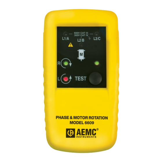
2.2 Control Features 600V CAT III 300V CAT IV L1/A L3/C L2/B TEST PHASE & MOTOR ROTATION MODEL 6609 Figure 1 1. Test lead input terminals 2. Phase indicators L1, L2, and L3 3. Green clockwise rotation LED 4. Red counter-clockwise rotation LED 5. Symbol for correct orientation on the motor 6. Green LED indicating the unit is ON 7. ON/OFF button Phase & Motor Rotation Tester Model 6609... -
Page 10: Specifications
-4° to 122°F (-20° to 50°C); RH < 80% Temperature SAFETY 600V CAT III IEC 61010-1, DIN VDE 0411; Safety Rating IEC 61557-7, DIN VDE 0413-7; Tightness : IP 40 (as per IEC 60529 Ed.92) Double Insulation CE Mark Phase & Motor Rotation Tester Model 6609... -
Page 11: Operation
OPERATION WARNING: Use only on motors rated 600V or less 4.1 Phase Rotation Direction On a three-phase electrical network: Connect the three leads to the instrument, matching the mark- ings. Connect the three alligator clips to the 3 phases of the network to be tested. Press the ON (TEST) button. The Green LED indicates that the instrument is in operation. When the indicators of all three phases are lit, the clockwise (or counter-clockwise) rotation indicator indicates the direction of phase rotation. Warning: The wrong direction of rotation may be displayed if a lead is connected in error to the neutral conductor. Refer to the instrument’s back label for a summary of the various display possibilities. Phase & Motor Rotation Tester Model 6609... -
Page 12: Indication Of Direction Of The Rotating Field, Or Direction Of Rotation Without Connecting Test Leads
Minimum Ø of the rotating field (per minute) as a between Number of motor casing function of frequency (Hz) poles pairs of poles 16 2/3 1000 3000 3600 1500 1800 10.7 1000 1200 16.0 21.4 26.7 32.1 42.8 53.5 64.2 3.75 85.6 Phase & Motor Rotation Tester Model 6609... -
Page 13: Determining The Direction Of Connection Of The Phase Wires To A Motor
Rotate the motor shaft to the right at a few RPM’s to get a stable reading on one of the LED rotations. The clockwise or counter-clockwise rotation indicator lights, indicating whether or not the order of connection of the phase wires is correct. 4.4 Solenoid Valve Activation Indication Do not connect any test leads to the instrument Place the instrument as close as possible to the solenoid valve. Press the ON button. The Green LED indicator indicates that the instrument is in operation. The clockwise or counter-clockwise rotation indicator lights, indicating the presence of the field generated during the acti- vation. Phase & Motor Rotation Tester Model 6609... -
Page 14: Maintenance
To replace the battery, proceed as follows: • Remove the screw on the bottom back of the instrument. • Remove the back cover. • Take out the battery and replace with a new 9V battery. (Type NEDA 1604, 6LF22, 6LR61) • Replace the back cover on the case. 5.2 Cleaning and Storage To avoid electrical shock or damage to the meter, do not get water inside the case. • Periodically wipe the case with a damp cloth and mild detergent • Dry completely before using again. • Do not use abrasives or solvents. • If the meter is not to be used for a period of longer then 60 days, remove the battery and store them separately. Phase & Motor Rotation Tester Model 6609... -
Page 15: Repair And Calibration
For instrument repair and calibration: You must contact our Service Center for a Customer Service Authorization Number (CSA#). This will ensure that when your instrument arrives, it will be tracked and processed promptly. Please write the CSA# on the outside of the shipping container. ® ® Ship To: Chauvin Arnoux , Inc. d.b.a. AEMC Instruments 15 Faraday Drive • Dover, NH 03820 USA Tel: (800) 945-2362 or (603) 749-6434 (Ext. 360) Fax: (603) 742-2346 or (603) 749-6309 repair@aemc.com (Or contact your authorized distributor) NOTE: You must obtain a CSA# before returning any instrument. Technical and Sales Assistance If you are experiencing any technical problems, or require any assistance... -
Page 16: Limited Warranty
® warranty is given by AEMC Instruments, not by the distributor from whom it was purchased. This warranty is void if the unit has been tampered with, abused or if the defect is related to service not performed by AEMC ® Instruments. For full and detailed warranty coverage, please read the Warranty Coverage Information, which is attached to the Warranty Registration Card (if enclosed) or is available at www.aemc.com. - Page 17 4.3 Determinación del sentido de conexión de los cables de las fases en un motor ........24 4.4 Indicación de la Activación de una válvula de solenoide ..............24 MANTENIMIENTO ............. 25 5.1 Cambio de pila .............25 5.2 Limpieza ...............25 Reparación y Calibración .............26 Asistencia Técnica y de Ventas ............26 Garantía Limitada .................27 Reparaciones bajo Garantía............27 Probador de Fase & Rotación de Motor Modelo 6609...
-
Page 18: Introducción
• Si el instrumento se utiliza de una forma no especificada en el presente manual, la protección proporcionada por el instrumento puede verse alterada. • No utilice este aparato si parece estar dañado. • Controle que el aislamiento de los cables y la carcasa estén en perfecto estado. Cambie los cables que estén dañados. • Tenga cuidado cuando trabaje con tensiones superiores a 70Vdc o 33Vrms y 46,7Vpp, estas tensiones pueden producir electrocu- ción. Dependiendo de las condiciones, se recomienda el uso de protecciones individuales. • Mantenga siempre sus manos detrás de las protecciones de las puntas de prueba o los clipes de cocodrilo • Desconecte siempre las puntas de prueba de los puntos de medida y del instrumento antes de abrir la carcasa. Probador de Fase & Rotación de Motor Modelo 6609... -
Page 19: Símbolos Eléctricos Internacionales
CAT III : Medición de la categoría III corresponde a las medicio- nes en las instalaciones en edificios. Ejemplo: cuadro de distribución, disyuntores, máquinas o aparatos industriales fijos. CAT IV : Medición de la categoría IV corresponde a las medicio- nes adoptadas en instalaciones de baja tensión. Ejemplo: entradas de energía, contadores y dispositi- vos de protección. Probador de Fase & Rotación de Motor Modelo 6609... -
Page 20: Recibiendo Su Pedido
Incluye medidor con tres cables de prueba (rojo, negro y azul), tres clips tipo cocodrilo, una batería de 9V, un maletín de transporte blando y manual del usuario. 1.4.1 Accesorios y repuestos Maletín de transporte blando ......... Cat. N° 2121.54 Conjunto de 3 cables con código de color con clips tipo cocodrilo negros CAT III 1000V 10A ..Cat. N° 2121.55 Probador de Fase & Rotación de Motor Modelo 6609... -
Page 21: Características Del Producto
Esta es también una herramienta ideal para medir la rotación adec- uada de los motores, transportadores, bombas y otros dispositivos eléctricos interconectados en el sistema de línea de alta tensión antes de la instalación NOTA: El modelo 6609 no requiere fusibles debido a que las entra- das están protegidas por un circuito de alta impedancia que limita la corriente a un valor seguro • Determinación del sentido de rotación de fases • Presencia o ausencia de fase • Determinación del sentido de rotación de un motor con o sin conexión ; • Determinación de la activación de la válvula de solenoide sin conexión. Probador de Fase & Rotación de Motor Modelo 6609... -
Page 22: Características De Los Controles
PHASE & MOTOR ROTATION MODEL 6609 1. Terminal de entrada del cable de prueba 2. Indicadores de fase L1, L2, y L3 3. Indicador verde LCD de rotación en el sentido a las agujas del reloj 4. Indicador rojo LCD de rotación en contrario a las agujas del reloj Símbolo de la correcta orientación del Modelo 6609 en el motor 6. LCD verde indicador de encendido del instrumento 7. Botón de encendido/apagado Probador de Fase & Rotación de Motor Modelo 6609... -
Page 23: Especificaciones
-4° hasta 122°F (-20° hasta 50°C); RH < 80% Almacenamiento SEGURIDAD 600V CAT III Calificación de IEC 61010-1, DIN VDE 0411; Seguridad IEC 61557-7, DIN VDE 0413-7; Hermeticidad : IP 40 (según IEC 60529 Ed.92) Doble Aislamiento Marca CE Probador de Fase & Rotación de Motor Modelo 6609... -
Page 24: Operación
ADVERTENCIA: Utilizar en motores con un Voltaje nominal de 600V o menor. 4.1 Sentido de rotación de fases En una red eléctrica trifásica: Conecte los 3 cables al instrumento de forma que correspon- dan a las marcas. Conecte las 3 pinzas cocodrilo a las 3 fases de la red a probar. Pulse el botón TEST. El indicador luminoso verde indica que el instrumento está funcionando. Cuando los 3 indicadores de fases están encendidos, el indicador de rotación en el sentido horario (o en el sentido contrario) indica el sentido de rotación de fases. Atención: se puede visualizar un sentido de rotación incorrecto si un cable se ha conectado, por error, al neutro de la red. Consulte la etiqueta del instrumento para obtener un resumen de los diversos posibilidades de visualización. Probador de Fase & Rotación de Motor Modelo 6609... -
Page 25: Indicación Del Sentido Del Campo Rotativo O Sentido De Rotación Sin Conexión
(1/min) según los polos cubierta del motor pares de la frecuencia (Hz) polos 16 2/3 1000 3000 3600 1500 1800 10.7 1000 1200 16.0 21.4 26.7 32.1 42.8 53.5 64.2 3.75 85.6 Probador de Fase & Rotación de Motor Modelo 6609... -
Page 26: Determinación Del Sentido De Conexión De Los Cables De Las Fases En Un Motor
Gire el eje del motor a la derecha unas pocas RPM para obte- ner una lectura estable en una de las rotaciones del LED; El indicador de rotación en el sentido horario o en el sentido contrario se enciende para indicar si se ha respetado o no el orden de conexión de los cables de las fases. 4.4 Indicación de la Activación de una válvula de solenoide Ningún cable debe estar conectado al instrumento. Posicione el instrumento lo más cerca posible de la válvula de solenoide. Pulse el botón TEST. El indicador luminoso verde indica que el instrumento está funcionando. El indicador de rotación en el sentido horario o en el sentido contrario se enciende para indicar la presencia del campo generado durante la activación. Probador de Fase & Rotación de Motor Modelo 6609... -
Page 27: Mantenimiento
Cambie la pila de 9V (tipo NEDA 1604, 6LF22, 6LR61) y vuelva a fijar la tapa mediante el tornillo. ADVERTENCIA: Desconecte siempre todas las pinzas de prueba antes de reemplazar la batería o el fusible. 5.2 Limpieza Periódicamente limpie la carcasa con un trapo mojado con detergente. Séquelo completamente antes de utilizarlo No utilice productos abrasivos Si el instrumento no es utilizado por un periodo superior a 60 días, desconecte la batería. ADVERTENCIA: Para evitar cortocircuitos o dañar el instrumento, no introduzca agua dentro de la carcasa. Probador de Fase & Rotación de Motor Modelo 6609... -
Page 28: Reparación Y Calibración
Asistencia Técnica y de Ventas Si tiene cualquier problema técnico o necesita ayuda para la correcta ope- ración o aplicación de su instrumento por favor llame, escriba, envíe un fax o e-mail a nuestro soporte técnico: Chauvin Arnoux , Inc. d.b.a. AEMC Instruments ® ® 200 Foxborough Boulevard • Foxborough, MA 02035, USA Phone: (800) 343-1391 or (508) 698-2115 Fax: (508) 698-2118 techsupport@aemc.com www.aemc.com NOTA: No envíe instrumentos a nuestra dirección en Foxborough, MA. Probador de Fase & Rotación de Motor Modelo 6609... -
Page 29: Garantía Limitada
Garantía Limitada El Probador de Fase & Rotación de Motor Modelo 6609 es garantizados al propietario por defectos de fabricación, por un período de dos años desde la fecha original de compra. Esta garantía limitada es dada por AEMC ® Instru-ments, no por el distribuidor a quien se compró el instrumento. Esta garantía queda viciada si la unidad ha sido intervenida, abusada o si la falla se rela-ciona con un servicio no realizado por AEMC Instruments. ® Para detalles y una descripción completa de la cobertura de la garan- tía, por favor lea la Tarjeta de Cobertura de Garantía, que se adjunta a la Tarjeta de Registro de Garantía. - Page 32 03/17 99-MAN 100337 v6 Chauvin Arnoux , Inc. d.b.a. AEMC Instruments ® ® 15 Faraday Drive • Dover, NH 03820 USA www.aemc.com...
Need help?
Do you have a question about the 6609 and is the answer not in the manual?
Questions and answers