
Related Manuals for AEMC 6503


Summary of Contents for AEMC 6503
- Page 1 6501 MEGOHMMETER 6503 E N G L I S H User Manual GlobalTestSupply www. .com Quality AEMC Products Online at: sales@GlobalTestSupply.com...
- Page 2 12 months and begins on the date of receipt by the customer. For recalibration, please use our calibration services. Refer to our repair and calibration section at www.aemc.com. Serial #: ________________________________ Catalog #: 2126.51 / 2126.52 Model #:...
-
Page 3: Table Of Contents
1.4.1 Accessories and Replacement Parts ....5 2. PRODUCT FEATURES ..........6 2.1 Description ..............6 2.2 Features ................6 2.3 Model 6501 Control Features ......... 8 2.4 Model 6503 Control Features ......... 9 3. SPECIFICATIONS ..........10 4. OPERATION ............12 4.1 Auto-ranging ..............12 4.2 Safety Check - Voltage Test .......... 12 4.3 Insulation Resistance Testing (MΩ Range) .... - Page 4 5. MAINTENANCE ............. 24 5.1 Warning ................ 24 5.2 Cleaning ................ 24 5.3 Fuse Replacement ............25 Repair and Calibration ..............26 Technical and Sales Assistance ........... 26 Limited Warranty ................27 Warranty Repairs ................27 GlobalTestSupply www. .com Quality AEMC Products Online at: sales@GlobalTestSupply.com...
-
Page 5: Introduction
• Safety is the responsibility of the operator! • Tests are to be carried out only on dead circuits! Check for live circuits before making resistance measure- ments (safety check). • These megohmmeters are rated for 600V CAT II or 300V CAT III - Pollution Degree 2. • The Megohmmeter Models 6501/6503 are sources of high voltage, as is the sample connected to them. All persons performing or assisting in the tests must employ all safety precautions to prevent electrical shock to themselves and to others. • AEMC Instruments considers the use of rubber gloves ® to be an excellent safety practice even if the equipment is properly operated and correctly grounded. • When testing capacitance samples, make sure that they have been properly discharged and that they are safe to touch. Dielectric insulation samples should be short-circuited for at least five times the amount of time they were energized. • Use the leads supplied with the megohmmeter. If defective or used, replace before testing. GlobalTestSupply www. .com Quality AEMC Products Online at: sales@GlobalTestSupply.com Megohmmeter Models 6501/6503... -
Page 6: International Electrical Symbols
CAT III: For measurements performed in the building installation at the distribution level such as on hardwired equipment in fixed installation and circuit breakers. CAT IV: For measurements performed at the primary electrical supply (<1000V) such as on primary overcurrent protec- tion devices, ripple control units, or meters. GlobalTestSupply www. .com Quality AEMC Products Online at: sales@GlobalTestSupply.com Megohmmeter Models 6501/6503... -
Page 7: Receiving Your Shipment
(black and red) and one safety test probe (6501) ..Cat. #2126.72 Replacement leads (black, red and blue), alligator clips (black, red and blue) and one safety test probe (6503)..Cat. #2126.73 Replacement Fuse - 0.2A, 600V HPC (6501) .... Cat. #2970.95 GlobalTestSupply www. -
Page 8: Product Features
These megohmmeters incorporate a built-in generator and a con- stant DC voltage circuit to provide a stable output and give direct insulation resistance reading. The Models 6501/6503 have a unique auto-ranging feature which expands the scale by x10 and almost doubles the scale length. When the pointer reaches near the end of scale, the auto-ranging feature activates, returning the pointer to the beginning of the scale with the x10 red LED indicator on. - Page 9 • Test voltage constant across the entire measurement range • Autoranging MΩ, kΩ and Ω ranges (Model 6501) • Autoranging MΩ ranges (Model 6503) • Designed for harsh environments: offshore, mining, heavy-duty field, industrial, and military use • Compact, self-contained package; folding crank • Large direct reading scale • 600V test voltage range (safety check) GlobalTestSupply www. .com Quality AEMC Products Online at: sales@GlobalTestSupply.com Megohmmeter Models 6501/6503...
-
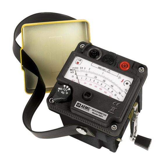
Page 10: Model 6501 Control Features
I N S T R U M E N T S Figure 2-1 1. Line (-) terminal Black 2. Fuse 0.2A 3. Earth (+) terminal Red 4. Amber LED illuminates when proper crank speed is attained, indicating presence of selected output 5. Foldaway handle 6. Mechanical zero adjustment screw 7. Range switch - safety test first on MΩ/V range to 600V 8. Autoranging: Red LED illuminates when reading needs to be multiplied x10 to obtain the true value (MΩ, kΩ, Ω ranges) 9. Security finger rest isolates users hand from terminals while giving a firm grip during an operation GlobalTestSupply www. .com Quality AEMC Products Online at: sales@GlobalTestSupply.com Megohmmeter Models 6501/6503... -
Page 11: Model 6503 Control Features
Figure 2-2 1. Line (-) terminal - Black 2. Guard terminal - Blue 3. Earth (+) terminal - Red 4. Green LED illuminates when proper crank speed is attained, indicating presence of selected test voltage 5. Foldaway handle 6. Mechanical zero adjustment screw 7. Range switch - Safety test first on 600V/V~ range to 600V 8. Autoranging: Red LED illuminates when reading needs to be multiplied x10 to obtain the true value (MΩ range) 9. Security finger rest isolates users hand from terminals while giving a firm grip during an operation GlobalTestSupply www. .com Quality AEMC Products Online at: sales@GlobalTestSupply.com Megohmmeter Models 6501/6503... -
Page 12: Specifications
2.5% of Scale Length − Fuse Protection 0.2A, 600V HPC 6x32mm − Voltage Tests/Safety Check Voltage Range 0 to 600V Frequency 45 to 450Hz Accuracy 3% of Scale Ω Input Impedance 100k (approx) GlobalTestSupply www. .com Quality AEMC Products Online at: sales@GlobalTestSupply.com Megohmmeter Models 6501/6503... - Page 13 IP54 with lid, IP52 without lid Rating EN 61010-1, 600V CAT II; 300V CAT III; Pollution Degree 2 Double Insulation CE Mark *Specifications are subject to change without notice GlobalTestSupply www. .com Quality AEMC Products Online at: sales@GlobalTestSupply.com Megohmmeter Models 6501/6503...
-
Page 14: Operation
4.2 Safety Check - Voltage Test Before measuring insulation resistance, confirm that the sample is fully discharged (particularly in dielectric and capacitance samples) and that the sample is not connected to an energized circuit. To perform the voltage test, set the range selection to V MΩ (Model 6501) or 500V MΩ (Model 6503), connect and read on the red voltage scale (600V max). DO NOT CRANK. If measuring on a DC circuit, the pointer will deflect but the measurement may be inaccurate. 4.3 Insulation Resistance Testing (MΩ Range) After checking for a live circuit (see safety check), select the test volt- age and connect the megohmmeter. Several connection examples are illustrated further. Crank the handle until the Amber LED (Model... -
Page 15: Test Voltage
It is not unusual for a winding to be 10 to 100 times the recom- mended minimum value (IEEE standard 43-2000: Recommended Practice for Testing Insulation Resistance of Rotating Machinery), but this varies with temperature and humidity. GlobalTestSupply www. .com Quality AEMC Products Online at: sales@GlobalTestSupply.com Megohmmeter Models 6501/6503... -
Page 16: Ratio Testing
Insulation resistance decreases with moisture, temperature and age and should be recorded over time at a given temperature and cor- rected. 4.4 Successful Insulation Resistance Testing • Check with the equipment manufacturer for factory insula- tion resistance readings. • Do not rely on insulation resistance testing alone as proof of winding conditions. • Do not expect the same value for all parts of all machines. • Observe consistent test time duration, recognizing that total current through insulation under test will vary with time. • Correct all readings properly to a standard reference tem- perature (see IEEE std #43-2000, Temperature Correction Curve). • Know what you are testing. Isolate the piece of equipment from other circuitry. • Watch trends rather than relying on single “spot” readings. GlobalTestSupply www. .com Quality AEMC Products Online at: sales@GlobalTestSupply.com Megohmmeter Models 6501/6503... -
Page 17: Utilization Of The Guard Terminal (Model 6503)
D = Exposed surface Figure 4-1 Guard terminals are useful when measuring high resistance values and for stabilizing readings. When testing the insulation at the end of a cable, it is necessary to eliminate the error from surface leakage which occurs, particularly at high resistance values. The purpose of the guard terminal is to provide a third terminal within the path of the surface leakage “D”. Connect the instrument as shown in Figure 4-1. If there is no shield at “B”, use a copper wire wound several times around the exposed surface “B”. (Note: If a shield is not available and you do not make up a shield around “B” and connect to the guard terminal (-), the measurement will be erroneous and lead to confusion as to the cable’s state.) GlobalTestSupply www. .com Quality AEMC Products Online at: sales@GlobalTestSupply.com Megohmmeter Models 6501/6503... - Page 18 See Figure 4-3. This type of measurement will give the true value of the resistance “Rx”, provid- ing the “Ry” and “Rz” are not too low. To Guard terminal Rx: resistance through insulation Ry: surface resistance Rz: surface resistance To LINE To EARTH terminal terminal Figure 4-3 GlobalTestSupply www. .com Quality AEMC Products Online at: sales@GlobalTestSupply.com Megohmmeter Models 6501/6503...
-
Page 19: Insulation Measurement - Connections
Insulation Measurement - Connections Figures 4-4 shows the connections to measure the insulation of one conductor to the other conductors. The cable should be dis- connected at both ends to avoid leakage through switchboards and panels. For the Model 6503, the connection to the guard terminal is used to eliminate the effects of surface leakage across exposed insulation at one end of the cable. Refer to the section on Utilization of the Guard Terminal (§ 4.5). Conductor Under Test... - Page 20 Figures 4-5 shows the connections for testing insulation from a supply conductor to ground (motor frame). Conductor Under Test Cable Insulation Figure 4-5 GlobalTestSupply www. .com Quality AEMC Products Online at: sales@GlobalTestSupply.com Megohmmeter Models 6501/6503...
- Page 21 Figure 4-6 shows the connections to a transformer (lighting or dis- tribution). Make sure that the switches and/or circuit breakers on both sides are open. Check the high voltage winding to ground, low voltage to ground, and the resistance between them with no winding ground. Tested Winding Transformer Grounding Lug Figure 4-6 GlobalTestSupply www. .com Quality AEMC Products Online at: sales@GlobalTestSupply.com Megohmmeter Models 6501/6503...
- Page 22 Figure 4-7 shows the connections for measuring the insulation of a three-phase line to ground by connecting the jumpers between phases. This gives a reading of all conductors at once. If a load such as a motor, heater, etc., is attached to the other end of the line, it will read the load resistance to ground at the same time. By removing the jumpers, readings can be made between the individual conduc- tors and ground. Jumpers Figure 4-7 GlobalTestSupply www. .com Quality AEMC Products Online at: sales@GlobalTestSupply.com Megohmmeter Models 6501/6503...
-
Page 23: Insulation Resistance On Motors
4.7 Insulation Resistance on Motors Figure 4-8 shows reading the resistance to ground of a three-phase motor winding. Since the three-phase motors are internally con- nected, it is only necessary to connect one lead to the motor lead and the other lead to the motor frame as shown. Figure 4-8 GlobalTestSupply www. .com Quality AEMC Products Online at: sales@GlobalTestSupply.com Megohmmeter Models 6501/6503... - Page 24 Figure 4-9 shows the windings of a three-phase motor separated. Sometimes this can be done at the lead terminals while other times the end bells must be removed to get at the lead wires of the coils. By connecting the megohmmeter as shown, the phase insulation resistance value can now be determined. Read between phases “A” and “B”, then “B” and “C”, then “C” and “A”. Figure 4-9 GlobalTestSupply www. .com Quality AEMC Products Online at: sales@GlobalTestSupply.com Megohmmeter Models 6501/6503...
- Page 25 Figure 4-10 shows connections for testing insulation from a supply conductor in a switchbox to ground (motor frame). An identical test may be carried out from the motor starter. Motor Side of Switch: Connection to One Leg Starter In Grounded Motor Frame Figure 4-10 GlobalTestSupply www. .com Quality AEMC Products Online at: sales@GlobalTestSupply.com Megohmmeter Models 6501/6503...
-
Page 26: Maintenance
Warning: If the crank speed LED is not ON during testing, the reading is not valid. Cleaning The megohmmeter may be gently cleaned with a soft cloth, soap and water. Dry immediately after cleaning. Avoid water penetration into the electronic module. Make sure the megohmmeter and all leads are dry before further use. GlobalTestSupply www. .com Quality AEMC Products Online at: sales@GlobalTestSupply.com Megohmmeter Models 6501/6503... -
Page 27: Fuse Replacement
5.3 Fuse Replacement WARNING: For your safety, fold the crank and disconnect all of the leads from the meter. • With a flat screwdriver or a coin, push and turn the fuse holder a quarter turn counter-clockwise. • Replace the fuse with an identical one - 0.2A, 600V HPC 6x32mm GlobalTestSupply www. .com Quality AEMC Products Online at: sales@GlobalTestSupply.com Megohmmeter Models 6501/6503... -
Page 28: Repair And Calibration
If you are experiencing any technical problems, or require any assistance with the proper operation or application of your instrument, please call, mail, fax or e-mail our technical support team: Chauvin Arnoux , Inc. d.b.a. AEMC Instruments ® ® 200 Foxborough Boulevard Foxborough, MA 02035 USA Phone: (800) 343-1391 (508) 698-2115 Fax: (508) 698-2118 E-mail: techsupport@aemc.com www.aemc.com NOTE: Do not ship Instruments to our Foxborough, MA address. GlobalTestSupply www. .com Quality AEMC Products Online at: sales@GlobalTestSupply.com Megohmmeter Models 6501/6503... -
Page 29: Limited Warranty
® For full and detailed warranty coverage, please read the Warranty Coverage Information, which is attached to the Warranty Registration Card (if enclosed) or is available at www.aemc.com. Please keep the Warranty Coverage Information with your records. What AEMC Instruments will do: ®... - Page 30 GlobalTestSupply www. .com Quality AEMC Products Online at: sales@GlobalTestSupply.com...
- Page 31 GlobalTestSupply www. .com Quality AEMC Products Online at: sales@GlobalTestSupply.com...
- Page 32 01/11 99-MAN 100328 v6 Chauvin Arnoux , Inc. d.b.a. AEMC Instruments ® ® 15 Faraday Drive • Dover, NH 03820 USA Phone: (603) 749-6434 • Fax: (603) 742-2346 www.aemc.com GlobalTestSupply www. .com Quality AEMC Products Online at: sales@GlobalTestSupply.com...
Need help?
Do you have a question about the 6503 and is the answer not in the manual?
Questions and answers