Table of Contents
Advertisement
Quick Links
Advertisement
Table of Contents

Related Manuals for AEMC 6505


Summary of Contents for AEMC 6505
- Page 1 6505 MEGOHMMETER E N G L I S H User Manual...
- Page 3 The recommended calibration interval for this instrument is 12 months and begins on the date of receipt by the customer. For recalibration, please use our calibration services. Refer to our repair and calibration section at www.aemc.com. Serial #: ________________________________ Catalog #: 2130.18 Model #:...
-
Page 4: Table Of Contents
Table of Contents INTRODUCTION ..................4 1.1 Symbols ..................4 1.2 Definition of Measurement Categories ........5 1.3 Receiving Your Shipment ............5 1.4 Ordering Information ..............6 1.4.1 Accessories ..............6 1.4.2 Replacement Parts ............6 PRODUCT FEATURES ................7 2.1 Description ................7 2.2 Control Features ...............8 2.3 Switch Functions ...............9 2.4 Button Functions ...............9 2.5 Display ..................10 2.5.1 Digital Display .............10 2.5.2 Bargraph Display ............10... - Page 5 4.4 Insulation Measurement ............18 4.5 PI Measurement ..............20 4.5.1 Adjustments of the PI ..........21 4.6 Adjustment of the Variable Test Voltage .........22 4.7 Adjustment of the Maximum Test Voltage .......22 4.8 Error Messages ..............23 MAINTENANCE ................... 24 5.1 Recharging the Battery ............24 5.2 Fuse Replacement ..............25 5.3 Cleaning ..................25 5.4 Storage ...................25 Repair and Calibration ................26 Technical and Sales Assistance ............26 Limited Warranty ...................27 Warranty Repairs ...................27...
-
Page 6: Introduction
CAUTION - Risk of Danger! Indicates a WARNING and that the operator must refer to the user manual for instructions before operating the instrument in all cases where this symbol is marked. Risk of electric shock. The voltage at the parts marked with this symbol may be dangerous. Megohmmeter Model 6505... -
Page 7: Definition Of Measurement Categories
CAT IV: For measurements performed at the primary electrical supply (<1000V) such as on primary overcurrent protection devices, ripple control units, or meters. Receiving Your Shipment Upon receiving your shipment, make sure that the contents are consistent with the ordering information. Notify your distributor of any missing items. If the equipment appears to be damaged, file a claim immediately with the carrier and notify your distributor at once, giving a detailed description of any damage. Save the damaged packing container to substantiate your claim. Megohmmeter Model 6505... -
Page 8: Ordering Information
Extra Large Tool Bag ............Cat. #2133.73 Safety alligator (red) 600V CAT IV ........Cat. #2140.52 Safety alligator (black) 600V CAT IV ........Cat. #2140.53 Safety alligator (blue) 600V CAT IV ........Cat. #2140.54 9.6V rechargeable NiMH battery pack......... Cat. #2960.21 Power Cord 115V US Plug ..........Cat. #5000.14 Order Accessories and Replacement Parts Directly Online Check our Storefront at www.aemc.com/store for availability Megohmmeter Model 6505... -
Page 9: Product Features
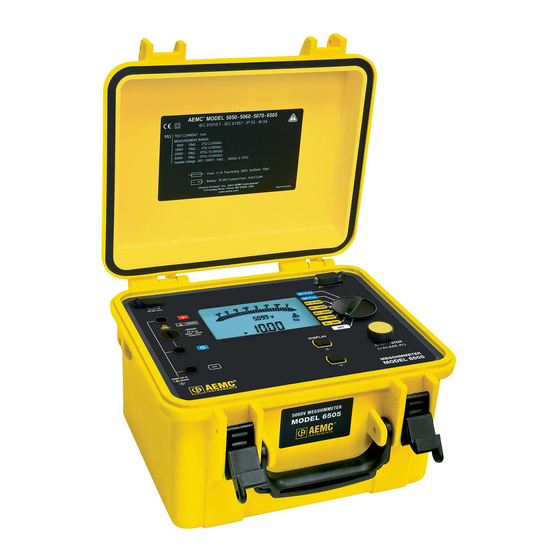
CHAPTER 2 PRODUCT FEATURES Description The Megohmmeter Model 6505 is a portable instrument housed in a rugged field case and operates on either battery or line power. It performs voltage, insulation, and capacitance measurements. This instrument contributes to the safety of electrical installations and equipment. Features include automatic calculation and presentation of the Dielectric Absorption Ratio (DAR) and Polarization Index (PI). The Model 6505 displays the test voltage, insulation resistance and the leakage current during the test. Capacitance of the sample and discharge voltage present at the test leads is displayed at the conclusion of the test. The Model 6505 is designed with the highest level of built-in safety fea- tures. This meter incorporates test inhibit capabilities which will not allow test voltages to be generated if a live sample is detected. The test termi- nals are recessed to ensure operating safety. Features: • Test voltage combination of 500V, 1000V, 2500V and 5000V •... -
Page 10: Control Features
AC power plug (direct operation on AC and battery recharge) Back-lit liquid crystal display (see § 2.5) Serial interface male plug (9-pin) for calibration only Rotary selector switch with 8 positions (see § 2.3) START/STOP button Two function buttons (see § 2.4) Megohmmeter Model 6505... -
Page 11: Switch Functions
This function is available only in the SET positions of the switch. Decreases ▼ the flashing parameter being displayed. To move about the list of interval insulation measurements in the R(t) function. NOTE: If the and buttons are held down, the movement between parameters is increased to a faster rate. Megohmmeter Model 6505... -
Page 12: Display
V >25V ± 3V or > 35V Indicates the duration of the measurement, or the time remaining in the case of a PI measurement. Indicates the battery is low and must be recharged (see § 5.1). Megohmmeter Model 6505... -
Page 13: Specifications
*Over 500Hz, the small display indicates “- - - -” and the main display gives only an assessment of the peak value of the measured voltage. Insulation Resistance Method: Voltage-current method according to EN 61557-2 (ed. 02/97) Nominal Output Voltage: 500, 1000, 2500, 5000V (or adjustable from 40 to 5100V) No Adjustment in Variable Mode: 10V from 40 to 1000V 100V from 1000 to 5100V Nominal Current: >1mA Megohmmeter Model 6505... - Page 14 6.400TΩ to R measured max 640.0GΩ 2.040TΩ 6.000TΩ 10.00TΩ To obtain the accuracy in variable voltage mode, calculate from the accuracies of the fixed voltages above. Measurement of the test voltage after a capacitive insulation measurement Measurement Range 25 to 5000V Resolution 0.2% Un or 1ct Accuracy 5% of Reading ± 3cts Megohmmeter Model 6505...
- Page 15 Calculation of terms DAR and PI Specified Range 0.02 - 50.00 Resolution 0.01 Accuracy 5% of Reading ± 1ct Typical change curve for test voltages according to load: Range 500V 0.01 MΩ Range 1000V 1200 1000 MΩ Megohmmeter Model 6505...
-
Page 16: Capacitance
2000 1500 1000 MΩ Range 5000V 6000 5000 4000 3000 2000 1000 MΩ Capacitance This measurement is made at the end of each insulation measurement, while the circuit is being discharged. Measurement Range 0.001 to 9.999 µF 10.00 to 49.99 µF Resolution 1 nF 10 nF Accuracy 10% of Reading ± 1ct Megohmmeter Model 6505... -
Page 17: Power Supply
20MΩ. In this case, the recharging time is higher than 6 hours and depends on the frequency of the measurements. Environmental Specifications Operating Range: 14° to 104°F (-10° to 40°C) during recharging of batteries 14° to 131°F (-10° to 55°C) during measurement 10 to 80% RH Storage: -40 to 158°F (-40 to 70°C); 10 to 90% RH Altitude: <2000m Use indoors or outdoors Megohmmeter Model 6505... -
Page 18: Mechanical Specifications
0.5% R / % Vn superimposed 0% to 20% Vn MΩ 0.1% R / % Vn ± 5cts on test voltage *The terms DAR, PI and the capacity and current leak measurements are included in the quantity “M Ω”. Megohmmeter Model 6505... -
Page 19: Operation
Serial Number To view the serial number of the instrument, keep the DISPLAY button pressed and turn the switch to the MΩ-500V position. Software Version To view the internal software version of the instrument, keep the DISPLAY button pressed and turn the switch to the MΩ-1000V position. Technical documentation on Understanding Insulation Resistance Testing is available on our website at www.aemc.com/techinfo. Voltage Measurement As soon as the switch is set to an insulation measurement position, the instrument automatically measures the presence of any AC/DC voltage. This voltage is measured at all times and indicated on the small display unit. The instrument automatically determines AC or DC. The AC measurement is an RMS value. -
Page 20: Insulation Measurement
Connect the red high-voltage lead between earth and the + terminal of the instrument. Connect the black high- voltage lead between one phase of the motor and the - terminal of the instrument. Strong Insulation For a very high insulation value, connect the small blue high-voltage lead between the rear earth pick-up jack of the black lead and the G terminal of the instrument. This serves to reduce any external influence and obtain a more stable measurement. Cable Connect the red high-voltage lead between the braid and the + terminal of the instrument. Exterior Core Insulation Insulation Connect the black Braid high-voltage lead between the core and the - terminal of the instrument. Connect the blue high-voltage lead between the insulation and the G terminal of the instrument. The guard serves to eliminate the effect of surface leakage currents. Megohmmeter Model 6505... - Page 21 (5 presses) • insulation resistance value just before the measurement was stopped • duration of the measurement • test voltage generated during the measurement • current that flowed in the resistance measured • surface leakage current • capacitance Megohmmeter Model 6505...
-
Page 22: Pi Measurement
1 min lasting 10 min)* DAR = R (2 values to be recorded during a measurement 1 min / 30 sec lasting 1 min) *For the calculation of the PI, the times of 1 and 10 minutes can be modified by the user, if required, for a particular application. See § 4.5.1. Megohmmeter Model 6505... -
Page 23: Adjustments Of The Pi
> 4 Excellent 4.5.1 Adjustments of the PI It is possible to modify the PI times to meet specific needs. Reminder: PI = R 10 min / 1 min The first PI time is 1 min. It can be set to values from 30 sec to 30 min in 30 sec steps. • Press and hold the DISPLAY button and turn the rotary switch to the SET V position. Hold the DISPLAY button until PI_1 appears in the display. • You can change the first PI time (PI_1) using the ▲ and ▼ buttons. • To save changes simply, turn the switch. • The second PI time (PI_2) is 10 min. It can be set to values from PI_1 up to 59 min in 1 min steps. • Press and hold the DISPLAY button and turn the rotary switch to the SET V position. LOCK • You can modify the second PI time using the ▲ and ▼ buttons. • To save changes simply, turn the switch. Megohmmeter Model 6505... -
Page 24: Adjustment Of The Variable Test Voltage
• Set the switch to MΩ 50-5000V to make the measurement. • This value is retained in a non-volatile memory. Adjustment of the Maximum Test Voltage The user can set a maximum generated voltage to prevent any accidental over-voltage tests being conducted in error. • Set the switch to SET V LOCK SET V LOCK SET V LOCK • The maximum test voltage flashes and can be adjusted using the ▲ and ▼ buttons. • Turn the switch to an insulation measurement setting to make measurements. • The maximum test voltage value is retained in a non-volatile memory. It will be displayed for a few seconds on selection of an affected range. (e.g. if the maximum voltage is 750V, it will be applied and displayed on all switch settings from 1000V up). Megohmmeter Model 6505... -
Page 25: Error Messages
• The insulation resistance is too low. • Check your connections. The + and - terminal of the instrument may be short-circuited. • The insulation resistance is outside the measurement range. • Check your connections. One of the terminals of the instrument may be disconnected or the value measured is > 4TΩ. • The voltage present on the terminals is greater than 25V or 35Vpeak. • The instrument alerts you but does not prevent making the measure- ment. • The voltage present on the terminals is too high for a measurement to be made: peak V > 0.4 Un The test voltage, Un, is indicated by the setting of the switch. • Eliminate the voltage and restart the measurement. • Indicates that the protective fuse of the G terminal is defective. • Replace the fuse as indicated in § 5.2. Megohmmeter Model 6505... -
Page 26: Maintenance
CHAPTER 5 MAINTENANCE Use only factory specified replacement parts. AEMC will not be held ® responsible for any accident, incident, or malfunction following a repair done other than by its service center or by an approved repair center. Recharging the Battery If the symbol displays, the battery needs to be recharged. Connect the instrument to the 115V power cord via the connector (charging starts automatically). -
Page 27: Fuse Replacement
• Using a coin or a flathead screwdriver, unscrew the fuse holder and remove the fuse. • Only replace with the type of fuse specified on the label inside the unit’s cover: 0.1A - Fast Acting - 380V, 5x20mm, 10kA NOTE: If after changing the fuse the display still indicates FUSE -G-, the instrument must be returned to the factory for servicing. Cleaning Disconnect the instrument from any source of electricity. Use a soft cloth lightly dampened with soapy water. Rinse with a damp cloth and then dry with a dry cloth. Do not use alcohol, solvents or hydrocarbons. Storage If the instrument is not used for an extended period of time, it is recom- mended to charge the instrument every two or three months. Megohmmeter Model 6505... -
Page 28: Repair And Calibration
Technical and Sales Assistance If you are experiencing any technical problems, or require any assistance with the proper operation or application of your instrument, please call, mail, fax or e-mail our technical support team: Chauvin Arnoux , Inc. d.b.a. AEMC Instruments ® ® 200 Foxborough Boulevard Foxborough, MA 02035 USA Phone: (800) 343-1391 (508) 698-2115 Fax: (508) 698-2118 E-mail: techsupport@aemc.com www.aemc.com NOTE: Do not ship instruments to our Foxborough, MA address. Megohmmeter Model 6505... -
Page 29: Limited Warranty
Ship To: Chauvin Arnoux , Inc. d.b.a. AEMC Instruments ® ® 15 Faraday Drive • Dover, NH 03820 USA Phone: ( 800) 945-2362 (Ext. 360) (603) 749-6434 (Ext. 360) Fax: (603) 742-2346 or (603) 749-6309 E-mail: r epair@aemc.com Caution: To protect yourself against in-transit loss, we recommend you insure your returned material. NOTE: You must obtain a CSA# before returning any instrument. Megohmmeter Model 6505... - Page 30 Notes: Megohmmeter Model 6505...
- Page 32 10/17 99-MAN 100339 v11 Chauvin Arnoux , Inc. d.b.a. AEMC Instruments ® ® 15 Faraday Drive • Dover, NH 03820 USA • Phone: (603) 749-6434 • Fax: (603) 742-2346 www.aemc.com...
Need help?
Do you have a question about the 6505 and is the answer not in the manual?
Questions and answers