Mellanox Technologies SX1012 User Manual
Switchx and switchx-2 series 1u switch systems
Hide thumbs
Also See for SX1012:
- Quick installation manual (9 pages) ,
- Quick reference manual (2 pages)
Table of Contents
Advertisement
Quick Links
Download this manual
See also:
Quick Reference Manual
Advertisement
Table of Contents

Related Manuals for Mellanox Technologies SX1012


Summary of Contents for Mellanox Technologies SX1012
- Page 1 Mellanox SwitchX and SwitchX®-2 1U Switch Systems Hardware User Manual Models: SX1012/SX1012X/SX1016/SX1024/SX1036/SX1400 Rev 1.4 Mellanox Technologies www.mellanox.com...
- Page 2 NOTE: THIS HARDWARE, SOFTWARE OR TEST SUITE PRODUCT (“PRODUCT (S)”) AND ITS RELATED DOCUMENTATION ARE PROVIDED BY MELLANOX TECHNOLOGIES “AS -IS” WITH ALL FAULTS OF ANY KIND AND SOLELY FOR THE PURPOSE OF AIDING THE CUSTOMER IN TESTING APPLICATIONS THAT USE THE PRODUCTS IN DESIGNATED SOLUTIONS.
-
Page 3: Table Of Contents
3.2.4 USB ............50 Rev 1.4 Mellanox Technologies... - Page 4 6.1 SX1012 Series ........
- Page 5 Figure 34: SFP+ Port LED Assignment ..........56 Rev 1.4 Mellanox Technologies...
- Page 6 Figure 38: RJ45 to DB9 Harness Pinout ..........104 Mellanox Technologies...
- Page 7 Table 20: SX1012/SX1012X Specifications ........
-
Page 8: Revision History
Added SX1012X May 2017 Edited “Unit Identification LED” June 2015 Added Hebrew safety warnings Added Japan VCCI Statement Removed SX1700Updated “Specifications” Updated “Mounting Options”c January 2015 Minor formatting edits January 2015 First release of the new edition Mellanox Technologies Rev 1.4... -
Page 9: About This Manual
This icon makes recommendations to the user. This icon indicates information that is helpful to the user. This icon indicates a situation that can potentially cause personal injury or damage to hardware or software. Risk of electric shock! Rev 1.4 Mellanox Technologies... -
Page 10: Chapter 1 Introduction To Mellanox Sx10Xx/Sx1X00 Systems
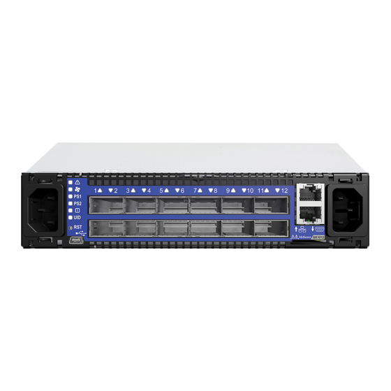
Figure 1: Ethernet Systems Family Front Side View Speed and Switching Table 3 describes maximum throughput and interface speed per system model. Table 3 - Speed and Switching Capabilities 10GbE* SFP+ System Model 40/56GbE QSFP+ Interfaces Throughput Interfaces SX1012 1.34Tb/s SX1012X 1.34Tb/s SX1016 1.28Tb/s SX1024 1.92Tb/s SX1036 4.03Tb/s... -
Page 11: Management Interfaces And Frus
Table 4 lists the various management interfaces and available replacement parts per system model. Table 4 - Management Interfaces and FRUs System Replaceable Replaceable Ports Ports Console Model Qty. Location SX1012/ Front Front Rear Front SX1012X (mini-USB) SX1016 Front Front Front (mini-USB) -
Page 12: Ordering Information
For more details, see “Air Flow” on page 18._ Table 5 - Ordering Part Numbers (OPNs) System Description Model SX1012 MSX1012B- SwitchX®-2 based 40GbE, 1U Open Ethernet Switch with MLNX-OS, 1BFS 12 QSFP+ ports, 1 Power Supply (AC), short depth, PPC460, Connector... - Page 13 36 QSFP+ ports, 2 Power Supplies (AC), PPC460, short depth, P2C air- flow, Rail Kit, RoHS6 MSX1036B-2SFS SwitchX®-2 based 40GbE, 1U Open Ethernet Switch with MLNX-OS, 36 QSFP+ ports, 2 Power Supplies (AC), PPC460, standard depth, C2P airflow, Rail Kit, RoHS6 Rev 1.4 Mellanox Technologies...
-
Page 14: Chapter 2 Installation
(Spanish),” on page 123. For Safety Warnings in Russian, see Section E.8, “Предупреждения по технике безопасности при установке (Russian),” on page 126. For Safety Warnings in Romanian, see Section E.9, “Avertismente privind siguranţa la instalare (Romanian),” on page 129. Rev 1.4 Mellanox Technologies... -
Page 15: Air Flow
Table 6 provides an air flow label color legend and respective OPN designations, Table 6 - Air Flow Label Legend Label Direction Description Designation Connector side inlet to power side outlet. Red labels are placed on the power inlet side. Mellanox Technologies Rev 1.4... -
Page 16: Figure 2: Air Flow Direction Marking - Connector Side Inlet To Power Side Outlet
Blue labels are placed on the power inlet side. Figure 2: Air Flow Direction Marking - Connector Side Inlet to Power Side Outlet Figure 3: Air Flow Direction Marking - Power Side Inlet to Connector Side Outlet Rev 1.4 Mellanox Technologies... -
Page 17: Package Contents
Package Contents The rear view shown in the above figures does not apply to SX1012/SX1012X, SX1016 and SX1024. Before installing your new system, unpack the system, and check, against the parts list below, that all the parts have been sent. Check the parts for visible damage that may have occurred during shipping. -
Page 18: Mounting Options
The following parts are included in the rail kit rack (see Figure 4): • Two rails • Two rail slides • Two system slides • 16 recessed flat head (6-32) screws (with extras) • 10 caged nuts • 10 pan head (M6) screw bolts Rev 1.4 Mellanox Technologies... -
Page 19: Figure 4: Rack Rail Kit Parts
Screw the system slides onto the system. Use 5 flat head 6-32 screws for a short system and Step 2. 7 screws for a standard depth system to connect each system slide. The recommended tight- ening torque is 1.5±0.2 Nm. Mellanox Technologies Rev 1.4... -
Page 20: Figure 5: Screwing On The Rail
Second side Slide the rail into the rail slide. Step 4. Using two of the M6 bolts for each corner, install the rails and rail slides in the rack. Do not Step 5. tighten the bolts yet. Rev 1.4 Mellanox Technologies... -
Page 21: Figure 7: Slide The Rail Into The Rail Slide
This side of the rail kit goes on the side of the rack you will slide the system into. This is the same side of the system that will be next to the vertical support. Figure 8: Installing the Slides Mellanox Technologies Rev 1.4... -
Page 22: Figure 9: System Placement In The Rack
Installation Slide the system into the rails. Step 6. Place the system and screw the bolts into the nuts. Tighten the bolts to 4.5±0.5 Nm. Step 7. Figure 9: System Placement in the Rack Rev 1.4 Mellanox Technologies... -
Page 23: Side-By-Side
The installation kits come with enough system mounted rails and flat head screws to install two systems. The 2 system frames will fit into racks with from 21” (533mm) to 34” (864mm) between the ver- tical supports. Mellanox Technologies Rev 1.4... -
Page 24: Figure 11: Installation Kit Parts For A Side By Side Installation
Installation Figure 11: Installation Kit Parts for a Side by Side Installation Rev 1.4 Mellanox Technologies... -
Page 25: Figure 12: Screw On The System Mounted Rails
Screw the two systems mounted rails to the system, using six flat head screws per rail. The Step 2. recommended torque is 0.7±0.1 Nm. Figure 12: Screw on the System Mounted Rails Install the two system frame into the rack. Slide the frame slides into the frame. Step 1. Mellanox Technologies Rev 1.4... -
Page 26: Figure 13: Two Systems Frame
Place the frame in the rack. Both sides of the frame must be on the inside of the rack. Step 2. Figure 14: Placement of Frame in the Rack Take the 10 spacer bushings and use them to adapt the square openings in the vertical sup- Step 3. port. Rev 1.4 Mellanox Technologies... -
Page 27: Figure 15: Placing The Spacer In The Rack
Use the 10 M5 pan head screws. Do not tighten the screws to the frame. Step 4. Figure 16: Using the Spacer Bushings Slide the system into the frame, and screw in the capture bolts into the frame. Step 5. Mellanox Technologies Rev 1.4... -
Page 28: Figure 17: Insert System Into Frame
Included in the box is a bag with 4 rubber stick-on feet for table top installation. Table Top Installation Peel and stick the four rubber bumpers into the bottom of the system. Place them in the Step 1. round circles. Rev 1.4 Mellanox Technologies... -
Page 29: Figure 18: Placing The Bumpers
Figure 18: Placing the Bumpers Bottom of the system Place on a flat surface. Make sure the system sits solid on the surface. Step 2. Connect the power cord. Step 3. Connect the data transfer cables. Step 4. Mellanox Technologies Rev 1.4... -
Page 30: Grounding
Test the ground using an Ohm meter. Some national and/or local codes may require IT components to be bonded and exter- nally grounded (not including the power cord ground). You must follow all national and local codes when installing this equipment. Rev 1.4 Mellanox Technologies... -
Page 31: Cable Installation
When using this feature you should login into the MLNX-OS® CLI and configure the individual ports to be ‘split-2’ or ‘split-4’. For further information and guidance, it is recommended to read more about Mellanox breakout cables on the Mellanox Community Website. Mellanox Technologies Rev 1.4... -
Page 32: Figure 20: Breakout Or Fanout Cable
Installation Figure 20: Breakout or Fanout Cable 2.6.1.1 SX1012/SX1012X In this switch, all ports can be split to 4x10GbE, no limitation. 2.6.1.2 SX1024/SX1400 Figure 21: SX1024/SX1400 Port Splitting Options This port can be split into 4 or 2 10Gb/s SFP+ This port is unmapped according to the Port Splitting Table Rev 1.4... -
Page 33: Figure 22: Sx1036 Port Splitting Options
Yes, disables port 24 Yes, disables port 12 Yes, disables port 30 Yes, disables port 7 Yes, disables port 25 Yes, disables port 13 — Yes, disables port 31 Yes, disables port 18 — Yes, disables port 36 Mellanox Technologies Rev 1.4... -
Page 34: Sfp+ Removal Tool
SFP+ Removal Tool There is a special tool to remove SFP+ cables from switches (such as SX1016 and SX1024/ SX1400) with 3 rows of SFP+ ports. To remove SFP+ cables follow the instruction in the figure below. Rev 1.4 Mellanox Technologies... -
Page 35: Figure 24: Sfp+ Removal And Insertion Tool
Figure 24: SFP+ Removal and Insertion Tool Mellanox Technologies Rev 1.4... -
Page 36: Initial Power On
Check the System Status LEDs and confirm that all of the LEDs show status lights consis- Step 4. tent with normal operation, as shown in Figure 25 below. For more information, refer to “LEDs” on page 51. Rev 1.4 Mellanox Technologies... -
Page 37: Figure 25: System Status Leds 5 Minutes After Power On
Figure 25: System Status LEDs 5 Minutes After Power On System with 1 PSU System with 2 PSUs Mellanox Technologies Rev 1.4... -
Page 38: System Bring-Up
Connect a host PC to the Console RJ45 port of the system using the supplied har- Step 1. ness cable (DB9 to RJ45). Make sure to connect to the Console RJ45 port and not to the (Ethernet) MGT port. Rev 1.4 Mellanox Technologies... -
Page 39: Table 9: Serial Terminal Program Configuration
Step 4: Enable IPv6 auto-con- This turns on auto-configuration of the IPv6 addresses. This is fig (SLAAC) on mgmt0 inter- unsuitable for DHCPv6. face? [no] If you enter "no" (no IPv6), you will automatically be referred to Step 6. Mellanox Technologies Rev 1.4... - Page 40 <enter> to save changes and To re-run the configuration wizard, run the command “configura- exit. tion jump-start” in Config mode. Choice: <Enter> Configuration changes saved. The table below shows an example of static IP configuration for mgmt0 interface. Rev 1.4 Mellanox Technologies...
-
Page 41: Table 11: Configuration Wizard Session - Static Ip Configuration
To change an answer, enter the step number to return to. Otherwise hit <enter> to save changes and exit. Choice: Configuration changes saved. To return to the wizard from the CLI, enter the “configuration jump-start” command from configure mode. Launching CLI... > Mellanox Technologies Rev 1.4... -
Page 42: Remote Connection
Once the network attributes are set, you can access the CLI via SSH or the WebUI via HTTP/ HTTPs. To access the CLI, perform the following steps: Set up an Ethernet connection between the system and a local network machine using a Step 1. standard RJ45 connector. Rev 1.4 Mellanox Technologies... -
Page 43: Fru Replacements
2.10 FRU Replacements Never run the system more than 5 minutes with an uncovered (open) PSU or fan slot. This section does not apply to SX1012/SX1012X 2.10.1 Power Supply and Fans 2.10.1.1 Power Supply Mellanox systems equipped with two replaceable power supply units work in a redundant config- uration. -
Page 44: Figure 27: Power Supply Unit Extraction
Insert the other end of the power cord into an outlet of the correct voltage. Step 5. The green power supply unit indicator should light. If not, repeat the whole procedure to extract the power supply unit and re-insert it. Rev 1.4 Mellanox Technologies... -
Page 45: Figure 29: Fan Module Latches
The green Fan Status LED should light. If not, extract the fan unit and reinsert it. After system two unsuccessful attempts to install the fan unit, power off the before attempt- ing any system debug. Mellanox Technologies Rev 1.4... -
Page 46: Chapter 3 Interfaces
The systems offer LR4 transceivers support in the following ports: • SX1036 - ports 1,3,33,35 • SX1024/SX1400 - ports 50,52,54,56,58,60 • SX1012 - all ports 3.2.1 Speed Ethernet speed must be set manually. The SFP+ ports can be manually configured to run at speeds ranging from 1GbE to 10 GbE. -
Page 47: Rs232 (Console)
The I2C connector is located either on the power supply side (banana connector), or on the front side (RJ45 connector). The I2C interface is used for debugging and is intended for Mellanox debug person- nel only. Mellanox Technologies Rev 1.4... -
Page 48: Reset Button
The Status LEDs are located to the left side of the front panel and on the power side at the far right. The port LEDs are located on top of the data ports- see Section 3.3. Rev 1.4 Mellanox Technologies... -
Page 49: Figure 30: System Status Leds - Front And Rear Sides
Both of the System Status LEDs (front and back) supply identical information. It may take up to five minutes to turn on the system. If the System Status LED shows red after five minutes, unplug the system and call your Mellanox representative for assistance. Mellanox Technologies Rev 1.4... -
Page 50: Figure 31: Fan Status Led - Front And Rear Sides
All fans are up and running (nor- Green mal condition). Solid Red Error, one or more fans is not In case there is an FRU, the module should be replaced. operating properly. Otherwise, the system should be replaced. Rev 1.4 Mellanox Technologies... -
Page 51: Figure 32: Power Status Led
PS2 are combined into one LED. Figure 33: Rear Side Panel Power Supply Unit The primary power supply (PS) unit is located on the left side and the secondary unit is located on the right side. Mellanox Technologies Rev 1.4... -
Page 52: Table 15: Power Supply Unit Status Led Assignments
The UID LED is a debug feature, that upon user configuration, lights a blue LED for ease in find- ing a particular system within a cluster. This is a future feature that is not yet available. Rev 1.4 Mellanox Technologies... -
Page 53: Inventory Pull-Out Tab
The system’s inventory parameters (such as serial number, part number and MAC address) can be extracted from the Inventory pull-out tab on the lower right side of the front panel. SX1016 does not contain an inventory pull-out tab. Mellanox Technologies Rev 1.4... -
Page 54: Figure 36: Pull-Out Tab
Interfaces Figure 36: Pull-out Tab Rev 1.4 Mellanox Technologies... -
Page 55: Chapter 4 Software Management
SwitchX®-2 based managed systems. MLNX-OS® includes a CLI, WebUI, SNMP, system management software and IB management software (OpenSM). The Ethernet ports for remote management connect to Ethernet systems. These sys- tems must be configured to 100Mb/1 Gb auto-negotiation. Mellanox Technologies Rev 1.4... -
Page 56: Chapter 5 Troubleshooting
• Replace the FAN FRU if needed. PSU Status LED is red This state is indicative of a problem with the PSU. • Check/replace the power cable. • Replace the PSU if needed. Mellanox Technologies Rev 1.4... - Page 57 01 00 15b3 bd34 0c06 00 Net: ppc_4xx_eth0, ppc_4xx_eth1 Hit Ctrl+B to stop autoboot: 0 Mellanox MLNX-OS Boot Menu: 1. SX_PPC_M460EX 3.3.5006-dev-HA 2013-04- 10 12:02:49 ppc 2. SX_PPC_M460EX 3.3.5006-dev-HA 2013-04- 11 14:05:39 ppc 3. U-Boot prompt Choice: Rev 1.4 Mellanox Technologies...
- Page 58 Press enter to boot the selected image or 'p' to enter a password to unlock the next set of features. Highlighted entry is 0: " • Select previous image to boot by pressing an arrow key and choosing the appropriate image. Mellanox Technologies Rev 1.4...
-
Page 59: Chapter 6 Specifications
Mounting: side by side for 19” rack mount or table top. Weight: System with 1 PSU: 2.98kg/6.57lbs System with 2 PSUs: 3.2kg/7.05lbs Speed: 10, 40 or 56 GbE per port in SX1012 10GbE per port in SX1012X Connector cage: 12 QSFP+ Heat dissipation: 293 BTUs/hr... -
Page 60: Sx1016 Series
Input Voltage: 100 - 240 VAC 50-60Hz Max Consumption: Active Cables: 239.53 Passive cables: 156.84 Typical (ATIS score under "snake" topology): With passive cables: 63.99W Main Devices CPU: PPC460EX Switch: Mellanox SwitchX Switching Capacity: 640Gb/s non-blocking Rev 1.4 Mellanox Technologies... -
Page 61: Sx1024 Series
Input Voltage: 100 - 240 VAC 50-60Hz Max Consumption: Passive cables: 175 W Active Cables: 263 W Optical cables: 267 W Typical (ATIS score under "snake" topology): With passive cables: 73.15 Main Devices CPU: PPC460EX Switch: Mellanox SwitchX® Switching Capacity: 1.15Tb/s non-blocking Mellanox Technologies Rev 1.4... -
Page 62: Sx1036 Series
Active Cables: 224W – 6.2 W/port Passive cables: 119W – 3.3W/port Typ Consumption: Active Cables: 182W – 5W/port Passive cables: 100W – 2.8W/port Typical (ATIS score under "snake" topology): 79.42 Main Devices CPU: PPC460EX Switch: Mellanox SwitchX® Switching Capacity: 2.02Tb/s non-blocking Rev 1.4 Mellanox Technologies... -
Page 63: Appendix A Accessory And Replacement Parts
Fan module with connector side to power supply side for MSX60XX and MSX10XX series switch systems MSX60-DKIT Rack installation kit for SX6005/SX6012 and SX1012 series short depth 1U switches, allows installation of One or Two switches side-by-side into stan- dard depth racks. -
Page 64: Appendix B Thermal Threshold Definitions
When the SwitchX® device crosses this temperature, the firmware will automatically shut down the device. 3.Emergency – 130C In case the firmware fails to shut down the SwitchX® device upon crossing the Critical thresh- old, the SwitchX® device will auto-shutdown upon crossing the Emergency (130C) threshold. Mellanox Technologies Rev 1.4... -
Page 65: Appendix C Interface Specifications
Rx3p Receiver Non-Inverted Data Output Rx3n Receiver Inverted Data Output Ground Rx1p Receiver Non-Inverted Data Output Rx1n Receiver Inverted Data Output Ground Ground Rx2n Receiver Inverted Data Output 3 Receiver Non-Inverted Data Output 3 Rx2p Ground Rev 1.4 Mellanox Technologies... - Page 66 +3.3 V Power supply transmitter Vcc 1 +3.3 V Power Supply Low Power Mode LPMode Ground Transmitter Non-Inverted Data Input Tx3p Transmitter Inverted Data Input Tx3n Ground Transmitter Non-Inverted Data Input Tx1p Transmitter Inverted Data Input Tx1n Ground Mellanox Technologies Rev 1.4...
-
Page 67: Sfp+ Interface
SFP+ Interface 56.50 13.90 Mellanox Technologies 11.85 13.60 14.80 13.70 MTSFPP-SR Module 1.55 0.50 8.50 0.60 2.55 1.80 44.95 Figure 37: Rear View of Module With Pin Placement 13.70 8.50 Table 27 - SFP+ Interface Symbol Name Description VeeT Transmitter Ground (Common with Receiver Ground) TX_Fault Transmitter Fault. - Page 68 MOD_ABS pulls line low to indicate module is plugged in. e. LOS is open collector output. Should be pulled up with 4.7kΩ – 10kΩ on host board to a voltage between 2.0V and 3.6V. Logic 0 indicates normal operation; logic 1 indicates loss of signal. Mellanox Technologies Rev 1.4...
-
Page 69: Console And I2C Interface
Bl/W RXD- RJ-45_RXD Br/W Table 29 - RJ-45 I2C Pinout Connection Signal Pin# Color TXD+ RJ-45_SDA TXD- RXD+ TXD+ Pin 1 TXD- RJ45_SDA RXD+ Bl/W RXD- RJ-45_SCL RXD- RJ45_SCL Br/W Pin 8 Looking into the Socket Rev 1.4 Mellanox Technologies... -
Page 70: Figure 38: Rj45 To Db9 Harness Pinout
RJ45 to DB9 Harness Pinout In order to connect a host PC to the Console RJ45 port of the system, a RS232 harness cable (DB9 to RJ45) is supplied. Figure 38: RJ45 to DB9 Harness Pinout Mellanox Technologies Rev 1.4... -
Page 71: Appendix D Disassembly And Disposal
Dispose of this product and all of its parts in a responsible and environmentally friendly way. Follow the instructions found at http://www.mellanox.com/page/dismantling_procedures for proper disassembly and disposal of the switch, according to the WEEE directive. Rev 1.4 Mellanox Technologies... -
Page 72: Appendix E Safety Warnings (Multiple Languages)
This equipment should not be operated in an area with an ambient temperature exceed- ing the maximum recommended: 45°C (113°F). Moreover, to guarantee proper , allow at least 8cm (3 inches) of clearance around the ventilation openings. Rev 1.4 Mellanox Technologies... - Page 73 12. Equipment Installation This equipment should be installed, replaced, and/or serviced only by trained and qual- ified personnel. 13. Equipment Disposal Disposal of this equipment should be in accordance to all national laws and regula- tions. Mellanox Technologies Rev 1.4...
- Page 74 Caution: Slide/rail mounted equipment is not to be used as a shelf or a work space. The rails are not intended for sliding the unit away from the rack. It is for permanent instal- lation at final resting place only, not used for service and maintenance Rev 1.4 Mellanox Technologies...
- Page 75 <40 lbs 70 - 121 lbs >121 lbs 40 - 70 lbs <18 kgs 32 - 55 kgs >55 kgs 18 - 32 kgs ציוד כבד .המוצר כבד, ויש לשנעו באמצעות מעלית מכאנית כדי למנוע חבלה Mellanox Technologies Rev 1.4...
- Page 76 .רבה. לאזהרות נוספות, יש לעיין בעלון לצרכן מטעם יצרן הכבלים הרכבה על גבי מדף בארון כאשר מרכיבים מוצר זה על גבי מדף בארון, יש לנקוט באמצעי זהירות מיוחדים בכדי להבטיח שיוותר יציב. ככלל, יש להתחיל למלא את הארון מהמדף התחתון, ולהתקדם .כלפי מעלה Rev 1.4 Mellanox Technologies...
- Page 77 -ו RS232 על כבלים לחיבור היחידה לממשקי .()כאשר הם מצויים במעגל חשמלי שאינו מקור כוח מוגבל DP-2 או הגנה מפני מתח גבוה יש להקפיד על המצאותם בבניין ועל זמינותם של אמצעים להגנה מפני מתח גבוה בתקן Mellanox Technologies Rev 1.4...
-
Page 78: 安裝安全性警告 (Chinese)
בנורבגיה בלבד, יחידה זו מיועדת לחיבור למערכת אספקת חשמל מסוג אספקת חשמל מסוג 安裝安全性警告 (Chinese) 1. 安裝指示 本設備附有備援電源供應器或在適當位置配有空白蓋板。 2. 因重量導致的人身受傷 為了安全起見,請安排足夠的人員以合力抬起本產品。 <40 lbs 70 - 121 lbs >121 lbs 40 - 70 lbs <18 kgs 32 - 55 kgs >55 kgs 18 - 32 kgs Rev 1.4 Mellanox Technologies... - Page 79 本設備不應在超過所建議的最高環境溫度的區域中運作:45°C (113°F)。此外, 為了保證氣流的流通正常,請在通風口旁保留至少 8 公分 (3 英吋 ) 的間距。 6. 堆疊機箱 機箱不應堆疊在任何其他設備上。如果機箱掉落,可能造成人員受傷與設備損 壞。 7. 複式電源連接時的電擊危險 本設備附有備援電源供應器或在適當位置配有空白蓋板。如果是電源供應器空 白蓋板,在空白蓋板已取下或未牢牢固訂的情況下,請勿操作本產品。 8. 多電源輸入座 電擊與能源危害的危險。 所有 PSU 均各自獨立。 將所有電源供應器斷電,確保交換器平台內部在電源關閉狀態。 9. 閃電時的電擊危險 在閃電期間,不要使用本設備或連接或拔下纜線。 10. InfiniBand 銅纜連接 / 拔下 InfiniBand 銅纜很重且沒有彈性,因此必須小心裝在連接器上或自連接器上拔 下。如需相關的特殊警告 / 指示,請洽詢纜線製造商。 Mellanox Technologies Rev 1.4...
- Page 80 AWG] 附成型插頭,額定值為 125 V、[13 A],長度至少 1.5 公尺 [ 六英尺 ],但 不超過 4.5 公尺的電源線。 歐洲地區在接上電源時,請選用國際協調式且標示有 <HAR> 字樣、三個導體、 標稱截面至少 1.0 平方公厘,額定值為 300 V,採用 PVC 絕緣的電源線。電源 線需有成型插頭,額定值為 250 V, 10 A。 16. 高漏電流 警告: 高漏電流;必須執行地線連接,然後再連接電源供應器。 17. 安裝法規 請務必遵循最新版的國家電氣法規,安裝本設備。在北美地區,請務必遵循美 國國家電工法規和加拿大電工法規中的適用規定,安裝本設備。 Rev 1.4 Mellanox Technologies...
-
Page 81: Avertissements De Sécurité Pour L'installation (French)
根據 WEEE 指令 2002/96/EC,所有廢棄的電氣與電子設備 (EEE),應分開集 中,而且不應與一般家庭廢棄物一起棄置。 請以負責和環保的方式棄置本產品及其所有零件。 21. 挪威國家電源限制 本設備僅限連接至挪威的 TN 電源系統和 IT 電源系統。 Avertissements de sécurité pour l'installation (French) 1. Instructions d'installation Veuillez lire la totalité des instructions d'installation avant de relier l'équipement au secteur. Mellanox Technologies Rev 1.4... - Page 82 Dans ce dernier cas, ne pas faire fonctionner le produit si le cache est retiré ou mal fixé. 8. Plusieurs prises d'alimentation Risque et danger d'électrocution. Les alimentations sont toutes indépendantes. Pour s'assurer que le commutateur est bien hors tension, débranchez toutes les alimen- tations. Rev 1.4 Mellanox Technologies...
- Page 83 Cet appareil doit être installé conformément à la version la plus récente des codes élec- trique nationaux. En Amérique du Nord, l'équipement doit être installé en respectant les exigences de l'US National Electrical Code et du Code canadien de l'électricité. Mellanox Technologies Rev 1.4...
- Page 84 Ce produit et toutes ses pièces doivent être mis au rebut d'une manière responsable, respectant l'environnement. 21. Restrictions concernant l'alimentation pour la Norvège Cet appareil est prévu pour être relié à un système d'alimentation TN et un système d'alimentation informatique de Norvège uniquement. Rev 1.4 Mellanox Technologies...
-
Page 85: Installation Sicherheitshinweise(German)
8 cm (3 in.) Freiraum um die Belüftungsöffnungen sein, um einen einwandfreien Luftstrom zu gewährleisten. 6. Stapeln des Chassis Das Chassis sollte nicht auf andere Geräte gestapelt werden. Wenn das Chassis herunt- erfällt, kann es zu Verletzungen und Beschädigungen an Geräten führen. Mellanox Technologies Rev 1.4... - Page 86 14. Installationscodes Dieses Gerät muss entsprechend der aktuellsten Version des National Electrical Code installiert weden. In Nodamerika muss das Gerät gemäß den geltenden Anforderungen des US National Electrical Code und des Canadian Electrical Code installiert werden. Rev 1.4 Mellanox Technologies...
- Page 87 20. WEEE-Direktive Gemäß WEEE Directive 2002/96/EC müssen alle elektrischen und elektronischen Abfallgeräte (EEE) separat gesammelt und nichit mit normalem Haushaltsmüll ensorgt werden. Dieses Produkt und alle seine Teile in verantwortungsvoller und umweltfreundlicher Art und Weise entsorgen. Mellanox Technologies Rev 1.4...
-
Page 88: Advertencias De Seguridad De Instalación (Spanish)
8 cm (3 pulgadas) alrededor de las aberturas de ventilación. 6. Apilamiento del chasis Los chasis no se deben apilar sobre otros equipos. La caída del chasis podría causar lesiones corporales, así como daños al equipo. Rev 1.4 Mellanox Technologies... - Page 89 La instalación, el reemplazo y el mantenimiento de este equipo estarán a cargo única- mente de personal capacitado y competente. 13. Eliminación del equipo La eliminación definitiva de este equipo se debe efectuar conforme a todas las leyes y reglamentaciones nacionales. Mellanox Technologies Rev 1.4...
- Page 90 UL tipo DP-1 o DP-2. (Nota: cuando residen en circuito no de tipo LPS) Protección contra sobrecargas: Al cableado del edificio se debe incorporar un disposi- tivo de protección contra sobrecargas de circuito derivado, de fácil acceso, con una corriente nominal de 20 A. Rev 1.4 Mellanox Technologies...
-
Page 91: Предупреждения По Технике Безопасности При Установке (Russian)
70 - 121 lbs >121 lbs 40 - 70 lbs <18 kgs 32 - 55 kgs >55 kgs 18 - 32 kgs 3. Тяжелое оборудование Это тяжелое оборудование, поэтому его следует перемещать с помощью механического подъемника во избежание травм. Mellanox Technologies Rev 1.4... - Page 92 Во время грозы запрещается использовать оборудование и подключать или отключать кабели. 10. Подсоединение и отсоединение медных кабелей InfiniBand Медные кабели InfiniBand тяжелые и негибкие, поэтому следует осторожно их подсоединять и отсоединять. За особыми предупреждениями и указаниями следует обратиться к производителю кабеля. Rev 1.4 Mellanox Technologies...
- Page 93 сечением жилы не менее 1,0 мм², рассчитанного на номинальное напряжение 300 В, с ПВХ оболочкой. Шнур должен иметь литую вилку, рассчитанную на 250 В, 10 А. 17. Высокий ток утечки Осторожно! Высокий ток утечки. Заземлить перед подключением к электропитанию. Mellanox Technologies Rev 1.4...
-
Page 94: Avertismente Privind Siguranţa La Instalare (Romanian)
Apelaţi la un număr suficient de persoane pentru a ridica în siguranţă acest produs. <40 lbs 70 - 121 lbs >121 lbs 40 - 70 lbs <18 kgs 32 - 55 kgs >55 kgs 18 - 32 kgs Rev 1.4 Mellanox Technologies... - Page 95 10. Conectarea/deconectarea cablului din cupru InfiniBand Cablurile InfiniBand din cupru sunt grele şi inflexibile, de aceea trebuie să fie ataşate sau detaşate de conectori cu grijă. Consultaţi producătorul de cabluri pentru avertis- mente/instrucţiuni speciale. Mellanox Technologies Rev 1.4...
- Page 96 PVC. Cordonul de alimentare trebuie să fie prevăzut cu o fişă turnată cu putere nominală egală cu 250 V, 10 A. 17. Curent de scurgere de înaltă frecvenţă Avertisment: Curent de scurgere de înaltă frecvenţă; Împământarea este esenţială înainte de a conecta sursa de alimentare. Rev 1.4 Mellanox Technologies...
-
Page 97: Sigurnosna Upozorenja Za Instaliranje (Croatian)
2. Tjelesne ozljede uslijed težine Kako biste sigurno podignuli ovaj proizvod, koristite dovoljan broj ljudi. <40 lbs 70 - 121 lbs >121 lbs 40 - 70 lbs <18 kgs 32 - 55 kgs >55 kgs 18 - 32 kgs Mellanox Technologies Rev 1.4... - Page 98 Tijekom djelovanja munja, nemojte raditi na opremi ili spajati ili odspajati kabele. 10. Spajanje/Odspajanje bakrenog kabela InfiniBand Bakreni kabeli InfiniBand su teški i nesavitljivi i kao takvi se moraju pažljivo prikl- jučiti na ili isključiti iz konektora. Obratite se proizvođaču kabela za posebna upo- zorenja/upute. Rev 1.4 Mellanox Technologies...
- Page 99 300 V, s PVC izolacijom. Kabel mora imati lijevani utikač nazivnog napona od 250 V, nazivne struje od 10 A. 17. Veliko curenje struje Upozorenje: Veliko curenje struje; Prije spajanja napajanja nužno je spojiti uzeml- jenje. Mellanox Technologies Rev 1.4...
-
Page 100: Avvertenze Di Sicurezza Per L'installazione (Italiano)
Ovaj je uređaj namijenjen samo za spajanje na električni sustav s TN uzemljenjem i na električni sustav s IT uzemljenjem države Norveške. E.11 Avvertenze di sicurezza per l’installazione (italiano) 1. Istruzioni di installazione Leggere tutte le istruzioni di installazione prima di collegare l’apparecchiatura all’alimentazione. Rev 1.4 Mellanox Technologies... - Page 101 7. Collegamento di alimentazione ridondante - Pericoli elettrici Questo prodotto è dotato di un alimentatore ridondante o, qualora esso non sia installato, di uno spazio vuoto. Qualora l’alimentatore non sia installato, non utilizzare il prodotto con il coperchio rimosso o non fissato correttamente. Mellanox Technologies Rev 1.4...
- Page 102 Questo dispositivo va installato in conformità con l’ultima versione dei codici elettrici nazionali del Paese. Per il Nord America, l’apparecchiatura va installata in conformità con i requisiti applicabili del “codice elettrico nazionale USA” e del “codice elettrico canadese”. Rev 1.4 Mellanox Technologies...
- Page 103 Smaltire questo prodotto e tutte le sue parti in modo responsabile e rispettoso dell’ambiente 21. Limitazioni relative all’alimentazione per la Norvegia Questa apparecchiatura è progettata esclusivamente per il collegamento a un sistema di alimentazione TN e a un sistema di alimentazione IT. Mellanox Technologies Rev 1.4...
-
Page 104: Montaj Güvenlik Uyarıları (Türkçe)
45 °C (113 °F). Ayrıca, düzgün hava akışı sağlamak için havalandırma deliklerinin etrafında en az 8 cm (3 inç) açıklık bırakılmalıdır. 6. Şasi İstif Şasinin diğer herhangi bir ekipmanın üzerine istiflenmemesi gerekir. Şasi düşerse, fiziksel yaralanmalara ve ekipmanda hasara neden olabilir. Rev 1.4 Mellanox Technologies... - Page 105 Ekipmanın yalnızca eğitimli ve nitelikli personel tarafından monte edilmesi, değiştirilmesi ve/veya bakımının yapılması gerekir. 13. Ekipmanın Atılması Bu ekipmanın imhasında tüm ulusal yasalara ve düzenlemelere uyulması gerekir. 14. Yerel ve Ulusal Elektrik Kodları Bu ekipmanın montajında yerel ve ulusal elektrik kodlarına uyulması gerekir. Mellanox Technologies Rev 1.4...
- Page 106 20. WEEE Yönergesi WEEE Yönergesi 2002/96/EC uyarınca, tüm elektrikli ve elektronik ekipman atıkları (EEE) ayrı olarak toplanmalı ve evsel atıklarla birlikte çöpe atılmamalıdır. Bu ürün ve tüm parçaları çevreye dost ve sorumlu bir şekilde imha edilmelidir. Rev 1.4 Mellanox Technologies...
- Page 107 21. Norveç Güç Kısıtlamaları Bu ünite, bir TN güç sistemine ve sadece Norveç'in IT güç sistemine bağlanmak içindir. 22. Japan VCCI Statement Mellanox Technologies Rev 1.4...
Need help?
Do you have a question about the SX1012 and is the answer not in the manual?
Questions and answers