
Related Manuals for Mellanox Technologies SX6518-NR


Summary of Contents for Mellanox Technologies SX6518-NR
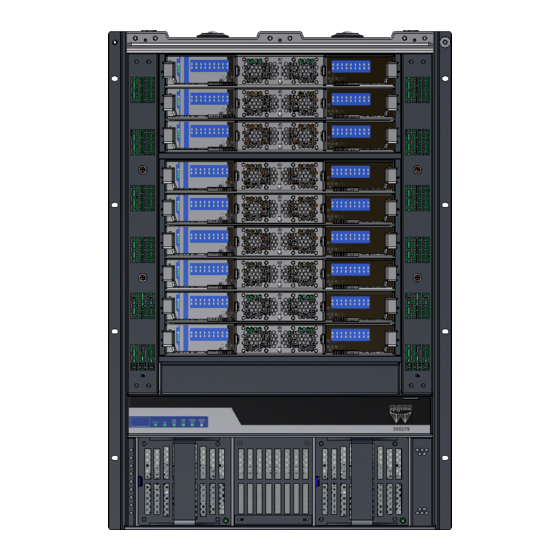
- Page 1 324-Port InfiniBand FDR SwitchX® Switch Platform Hardware Installation Guide PN:SX6518-NR, SX6518-6R Rev 1.3 www.mellanox.com...
- Page 2 Document Number: 3805 Mellanox Technologies...
-
Page 3: Table Of Contents
2.4.3 MGT– Management ......... 67 Mellanox Technologies... - Page 4 Avertismente privind siguranţa la instalare (Romanian) ..112 Sigurnosna upozorenja za instaliranje (Croatian) ....117 Mellanox Technologies...
-
Page 5: List Of Tables
Table 18: Configuration Wizard Session - IP Zeroconf Configuration ....74 Table 19: Configuration Wizard Session - Static IP Configuration ....75 Mellanox Technologies... -
Page 6: List Of Figures
Figure 37: Leaf Release ........... 45 Mellanox Technologies... - Page 7 Figure 72: Mechanical Lifting Device ......... 85 Mellanox Technologies...
-
Page 8: Revision History
This manual provides installation and set-up instructions for the SX6518 QSFP Chassis InfiniBand Switch Platform. Intended Audience This manual is intended for users and system administrators responsible for installing and setting up the chassis platform. ® The manual assumes familiarity with the InfiniBand architecture specification. Mellanox Technologies... -
Page 9: Table 2: Reference Documents And Websites
SwitchX®-based switch system/series release note file. Mellanox MLNX-OS® User Manual This document contains information regarding configuring and for VPI managing Mellanox Technologies SwitchX® switch platforms listing all of the commands available through MLNX-OS with explanations and examples. Conventions Throughout this manual, the name SX6518 and the terms chassis and switch are used to describe the 324 port QSFP InfiniBand chassis, unless explicitly indicated otherwise. -
Page 10: Mellanox Part Numbering Legend
InfiniBand Switch Platform Hardware User Manual Mellanox Part Numbering Legend Place Field Decoder Mellanox Technologies System Type SwitchX® Switch Data Transfer Protocol (1, 2, 3, 4) = Ethernet (5, 6, 7, 8) = InfiniBand Module Generation 5, 6, 7, 8... -
Page 11: Chapter 1 Installation
70 - 121 lbs >121 lbs 40 - 70 lbs <18 kgs 32 - 55 kgs >55 kgs 18 - 32 kgs 3. Heavy Equipment This equipment is very heavy and should be moved using a mechanical lift to avoid injuries. Mellanox Technologies... - Page 12 10. Multiple Power Inlets , Risk of electric shock and energy hazard. The PSUs are all independent. Disconnect all power supplies to ensure a powered down state inside of the switch platform. Mellanox Technologies...
- Page 13 This device must be installed according to the latest version of the country national electrical codes. For North America, equipment must be installed in accordance to the applicable requirements in the US National Electrical Code and the Canadian Electrical Code. Mellanox Technologies...
- Page 14 Cables for connecting to the unit RS232 and Ethernet Interfaces must be UL certified type DP-1 or DP-2. (Note- when residing in non LPS circuit) Overcurrent Protection: A readily accessible Listed branch circuit overcurrent protective device rated 20 A must be incorporated in the building wiring. Mellanox Technologies...
-
Page 15: Environmental And Safety Recommendations
This unit is intended for connection to a TN power system and an IT power system of Norway only. Environmental and Safety Recommendations The following are Mellanox recommendations. Recommended ambient temperature in the System room is 20 ± 5 Recommended humidity range is 40% ± 15% without condensing. Mellanox Technologies... -
Page 16: Chassis Package Contents
Check the parts for visible damage that may have occurred during shipping. If anything is damaged or missing, contact your customer representative immediately. Mellanox Technologies... -
Page 17: Leaf Package Contents
Make sure that a fully populated rack including cables will have sufficient air flow for cooling. Choose a rack which is able to support the mechanical and environmental characteris- tics of a fully populated switch chassis. Mellanox Technologies... -
Page 18: Starting With The Rack
1. Put an ESD prevention wrist strap on your wrist, and make sure there is good contact between your body and the strap. 2. Plug the other end of the wrist strap to a valid ground. Make sure that this is a tight fit. Mellanox Technologies... -
Page 19: Installation Procedure
- 26 pan head screws for the caged nuts 12 - 32 hex head bolts – 20 for the lock down for the shelf and 8 for the chassis faceplate bars and 12 for the upper brackets to upper and 6 for the filler panels bracket offsets Mellanox Technologies... -
Page 20: Figure 2: Installation Kit Parts
Top filler panel Lock-down bar 2 hole lock washer Shelf Shelf extension Upper bracket Bottom filler panel Upper bracket washer Upper bracket offset Flat washers hex head bolt Flat head screw Phillips pan head Lock washers Caged nuts screw Mellanox Technologies... -
Page 21: Figure 3: Shock And Tilt Stickers
But, be sure to carefully inspect the contents if any of the shock and tilt stickers have tripped. Figure 3: Shock and Tilt Stickers WA CH Stickers unaffected by shipping HANDLE WITH CARE HANDLE WITH CARE WA CH Stickers showing excessive shock or tilt. HANDLE WITH CARE HANDLE WITH CARE Mellanox Technologies... -
Page 22: Figure 4: Container Screws
• there is no visible damage • 6 PSUs are installed for the chassis • all 4 fans are installed 5. Remove all protective plastic film from all sides and top of the chassis. The leafs, spines, and management modules are shipped separately. Mellanox Technologies... - Page 23 The side of the chassis with the spine units will sit flush with the vertical supports of the rack. The side of the chassis with the QSFP connectors will sit at the edge of the shelf closer to the center of the rack. Mellanox Technologies...
-
Page 24: Figure 5: Vertical Rack Supports Dimension
4. Measure the distance between the vertical supports and adjust the shelf brackets according to this distance. This chassis can be installed in a rack with a distance between the vertical supports of from 65cm(25.6in.) to 80cm(31.5in.). Mellanox Technologies... -
Page 25: Figure 7: Adjustable Shelf Brackets
6. Move the shelf brackets on the shelf. Place the shelf bracket so that it measures slightly more than the measured distance between the vertical rack supports. Make Mellanox Technologies... -
Page 26: Figure 9: Placing The Shelf Bracket
You may need to remove the brackets and reinstall them. Figure 9: Placing the Shelf Bracket Adjusting slots Figure 10: Caged Nut Locations for the Shelf Brackets 4 caged nuts for the bottom filler panel go here here Mellanox Technologies... -
Page 27: Figure 11: Shelf Brackets
11. Tighten the 16 hex head bolts on the adjustable brackets. Figure 12: U Numbering Above Shelf The first cage nut on the spine side goes here. The rest of the caged nuts go every 4 U units up from here. Top of Shelf Mellanox Technologies... -
Page 28: Figure 13: Putting The Chassis In The Rack Using A Fork Lift
1. Put the container on the fork lift. Figure 13: Putting the Chassis in the Rack Using a Fork Lift The chassis is screwed down to the pallet on both the spine side and the leaf side. Mellanox Technologies... -
Page 29: Figure 14: Putting The Chassis In The Rack Using A Mechanical Lift
Figure 14: Putting the Chassis in the Rack Using a Mechanical Lift Figure 15: Place the Upper Bracket Offset 2. Screw on the two Upper Bracket offsets onto the chassis using nine flat head screws for each offset. Mellanox Technologies... -
Page 30: Figure 16: Attach The Shelf Extension
5. Place caged nuts in all of the locations specified in Figure 15. The black holes show where to place caged nuts; the red holes show the location of the upper brackets on the leaf side. Mellanox Technologies... -
Page 31: Figure 17: Caged Nut Placement By U Numbers
These are for the cable holder. Place 5 caged nuts here Bottom filler panel location Leaf Side Spine side Faceplate caged nuts go on this side Figure 18: Location for the Lock-Down Bar Bottom of the chassis Mellanox Technologies... -
Page 32: Figure 19: Fork Lift
10. Lower the chassis until the hinged extension is sitting on the shelf extension. 11. Push the chassis from the container to the shelf. Save the container pallet to remove this chassis. It will be necessary for the removal and disposal procedures. Mellanox Technologies... -
Page 33: Figure 21: Face Plate Mounting Bolt Locations
14. Slide the chassis out just far enough to install the upper brackets. See Figure 22. Figure 22: Upper Bracket Installation This hole is 60cm up from the top of the shelf. Use the socket wrench with both extensions to tighten these bolts. Mellanox Technologies... -
Page 34: Figure 23: Upper Brackets And Offset Location
19. For each offset and upper bracket, screw six bolts through the offset into the upper bracket. See Figure 24. Use one flat washer and one lock washer for each of these bolts. DO NOT TIGHTEN. Figure 25: Location for the Lock-Down Bar Bottom of the chassis Mellanox Technologies... -
Page 35: Figure 26: Lock-Down Bar
25. Tighten the upper bracket to upper bracket offset screws. See Figure 24. 26. Tighten the lock down bars. See Figure 27. 27. Connect the bottom filler panel below the shelf, bend facing out. 28. Connect the top filler panel directly above the top of the chassis. Mellanox Technologies... -
Page 36: Figure 28: Spine Side With Filler Panels
F ille r p a n e l S h e lf Fille r p an e l 29. Go to Chapter 3, “Chassis Power Up,” on page 69 to power up the switch system. 30. Insert 2 caged nuts for the filler panel. Mellanox Technologies... -
Page 37: Installing The Cable Holder
1. Place the cable holder next to the rack, on the connector side of the chassis, and iden- tify the holes where the caged nuts were placed in step 4 The cable holders should go to the outside of the vertical supports. Mellanox Technologies... -
Page 38: Ground Connections
PSU grounds. It is absolutely necessary to connect the grounding post. Make sure the connections are solid and permanent. If you choose to not use the ground screw, make sure that the rack is properly grounded and that there is a valid ground con- Mellanox Technologies... -
Page 39: Power Connections
Mellanox. The chassis in N+1 mode must be started with a full complement of PSUs, thereafter it can run on one less than the total number of PSUs. This final PSU is redundant and Mellanox Technologies... -
Page 40: Figure 31: Multiple Power Inlets - Electric Caution Notification
4. Check that none of the LEDs on the spines are yellow. It can take up to 5 minutes to boot up the system. Turn off the system if any LEDs remain red for more than 5 minutes. Mellanox Technologies... -
Page 41: Infiniband Qsfp Cable Installation
InfiniBand QSFP Cable Installation The switch uses industry standard QSFP InfiniBand cables which are available from Mellanox Technologies. The Mellanox proprietary QSFP cables support full 56+56Gb/s (FDR), 40+40Gb/s (FDR10), 40+40Gb/s (QDR), 20+20Gb/s (DDR) and 10+10Gb/s (SDR) bidirectional wire speed of the switch ports. All InfiniBand QSFP connections are made to the leaf boards. -
Page 42: Supported Approved Cables
FW versions. This switch platform supports hot swap capabilities for the parts listed below. • Power supply units • Leaf boards • Spine boards • Leaf fan module • Spine fan module • Management modules Mellanox Technologies... -
Page 43: 1.10.1 Power Supply Units
As the PSU unseats, the PSU status indicators will turn off. 5. Remove the PSU. To insert a PSU: 1. Make sure the mating connector of the new unit is free of any dirt and/or obstacles. Mellanox Technologies... -
Page 44: 1.10.2 Leaf Boards
Figure 35: Leaf Board Numbering 1.10.2.1 Extracting a Leaf Board Each leaf board has a ejector handle that locks the board in place and serves as a lever for seating or extracting (see Figure 36). Mellanox Technologies... -
Page 45: Figure 36: Ejector Handle
FW versions. To insert the leaf board: 1. Check for foreign objects in or mechanical damage to the chassis leaf slots. 2. Check leaf mechanics for any noticeable damage. Mellanox Technologies... -
Page 46: Figure 38: Intact Vs Defected Signal Connectors
Figure 39: Intact vs Defected Power Pin Holders Pass Fail 5. Start with the ejector handle fully open; that is, at 45 degrees to the front panel of the leaf. 6. Holding the leaf by its sides, carefully set the leaf board into the chassis. Mellanox Technologies... -
Page 47: 1.10.3 Spine Boards
When more than one spine slot is empty always insert the lowest spine board first, then work your way up. If you need to replace the bottom spine and it does not go in, try removing one or two spines above it and then insert the spines from the bottom up. Mellanox Technologies... -
Page 48: Figure 40: Management Module Numbering
If you have only one management module the chassis will crash! Figure 41: Spine Board Extraction Pull the ejector handles out to remove the spine. 21 23 25 29 31 15 17 20 22 Mellanox Technologies... - Page 49 Do not use the fan FRU handle to extract the spine board. 4. Pull out the module half-way through the guiding rails using both ejectors. 5. Lock the ejector handles. 6. Hold the body of the board on both sides and remove it from the chassis. Mellanox Technologies...
-
Page 50: Figure 42: Intact Vs Defected Mechanics
Fail Pass 3. Check back signal connectors’ integrity. Look for any broken signal dividers or any deviations from the pass criteria shown in Figure 43 and Figure 44. Figure 43: Intact vs Defected Side Signal Connectors Fail Pass Mellanox Technologies... -
Page 51: Figure 44: Intact Vs Defected Middle Signal Connectors
Figure 45. Figure 45: Intact vs Defected Power Pin Holders Fail Pass 5. Note the following sticker placed on the top of the spine board. Figure 46: Spine Board Insertion Caution Mellanox Technologies... -
Page 52: 1.10.4 Fan Modules
There are four leaf fan modules. Two leaf fan modules are found on the leaf side and two leaf fan modules are found on the spine side. The leaf side fans are not interchangeable with the spine side fans. Air flow through the leafs is independent of the air flow through the spines. Mellanox Technologies... -
Page 53: Figure 47: Leaf Fan Locations On The Chassis
FW versions. 1. Make sure the fan module is oriented correctly top side up. Confirm that the location of the connector in the chassis will line up with the connector in the fan module. Mellanox Technologies... -
Page 54: Figure 49: Spine Fan Module
FW versions. 1. Make sure the fan module is oriented correctly top side up. Confirm that the location of the connector in the chassis will line up with the connector in the fan module. Mellanox Technologies... -
Page 55: 1.10.5 Management Module
7. Hold the body of the board on both sides and remove it from the chassis. The board is short, therefore do not let go of it while sliding it out. Figure 51: Management Module S.FANS L.FANS Master CONSOLE Ejectors Mellanox Technologies... -
Page 56: Figure 52: Intact Vs Defected Signal Connectors
Figure 53: Intact vs Defected Power Pin Holders Fail Pass 5. Start with the ejector handles fully open; that is, at 45 degrees to the front panel of the management. 6. Holding the management by its sides, carefully set the management board into the chassis. Mellanox Technologies... -
Page 57: 1.10.6 Switch Shut-Down Procedures
To shut down a leaf run the following command: no power enable <module> To shut down a spine run the following command: no power enable <module> To shut down a management module run the following command: no power enable <module> Mellanox Technologies... -
Page 58: Chapter 2 Interfaces
DC OK – When lit this LED indicates that the output from the power supply is +48 VDC. The PSUs are on the spine side of the chassis behind two cover panels. The plugs for these PSUs are on the leaf side of the chassis. Mellanox Technologies... -
Page 59: Leaf Board Led Indicators
Leaf Board LED Indicators Figure 56: Leaf Board Led Indicators 2.1.2.1 Status LED Each leaf board has a Status LED on the far left of the leaf. Table 3 shows the leaf status according to the LED condition. Mellanox Technologies... -
Page 60: Table 3: Leaf Status Led
2.1.2.3 UID LED Switch Identifier The UID LED is a debug feature that will become available to customers in the near future. For details please contact Mellanox Technologies support. 2.1.2.4 Leaf Board Port Connector LED Assignment Above the ports are two LEDs one for the upper port and one for the lower port Each port has a single 2 color LED. -
Page 61: Spine Board Led Indicators
36 then some of the leaf to spine connection LEDs may be OFF. The status LEDs for the spine and their descriptions are shown in Table 6. The LEDs indicate as follows. Mellanox Technologies... -
Page 62: Table 6: Spine Status Led
LED Color LED Description Solid Green Spine Fan is OK Flashing Green Spine Fan needs replacing Solid Yellow One or more of the fans in this spine is not working Each spine has two fans in the fan module Mellanox Technologies... -
Page 63: Spine Side Panel Display Led Indicators
2.1.3.5 UID LED Switch Identifier The UID LED is a debug feature that will become available to customers in the near future. For details please contact Mellanox Technologies support. 2.1.4 Spine Side Panel Display LED Indicators The spine side panel display has LEDs that show the chassis condition. -
Page 64: Management Module Led Indicators
- this management module is not the master Green – Management module is operating as a master 2.1.5 Management Module LED Indicators Figure 59: Management Module Status Indications CONSOLE STATUS The management module LEDs display the switch system operating conditions. Mellanox Technologies... -
Page 65: Table 11: Leds Display For Normal Operation
Table 12 - Configurations LED Condition Description Green OK – All PSUs are working at correct input and output voltages. Error – One or more of the PSUs for the chassis is bad. Check each PSU for a red LED. Mellanox Technologies... -
Page 66: Port Connector Interfaces
The ports on each leaf board are placed in two rows, 9 ports to a row. The ports are labelled as shown in Figure 61. The bottom row ports are flipped from the top row. See Figure 62. Figure 61: Port Numbering Figure 62: Top and Bottom Ports Mellanox Technologies... -
Page 67: Air Flow
See the Installation Guide for the initial configuration procedure. 2.4.3 MGT– Management The MGT port is an Ethernet port for remote management. Any remote terminal con- nected to the Ethernet port can then be used to manage the fabric and chassis. Mellanox Technologies... -
Page 68: Usb
When the button is held down for 15 seconds the management module is reset and the password is deleted. You will then be able to enter without a password and make a new password for the user “admin”. Mellanox Technologies... -
Page 69: Chapter 3 Chassis Power Up
6. Tighten all leaf and spine mounting screws. 7. Connect the power cords to the PSUs. 8. Connect the power cords to grounded electrical outlets. With N+1 PSU redundancy do not power up the chassis with less than all PSUs installed. Mellanox Technologies... -
Page 70: Power Supply And Spine Board Indicator Status At Power On
4. Check the Spine LEDs and make sure they coincide with Figure 65. Figure 65: Spine Side Panel Display Status Indications 5. Check the Management Module LEDs and make sure they coincide with Figure 66. Figure 66: Management Module Status Indications for Normal Operation S.FANS L.FANS Master CONSOLE Mellanox Technologies... -
Page 71: Chapter 4 First-Time Configuration
Initial configuration must be performed on all of the management modules. Make sure to connect to the console RJ-45 port of the switch and not to the MGT port. No remote IP connection is available at this stage. Mellanox Technologies... -
Page 72: Table 16: Serial Terminal Program Configuration
Step 3: Enable IPv6 [yes] Perform this step to enable IPv6 on manage- ment ports. If you wish to enable IPv6, type “yes” and press <Enter>. If you enter “no” (no IPv6), then you will auto- matically be referred to Step 5. Mellanox Technologies... - Page 73 Otherwise hit <enter> to save changes and exit. start” you must be in Config mode. Choice: <Enter> Configuration changes saved. To return to the wizard from the CLI, enter the “configuration jump-start” command from configuration mode. Launching CLI... <switch name> [standalone: master] > Mellanox Technologies...
-
Page 74: Table 18: Configuration Wizard Session - Ip Zeroconf Configuration
To change an answer, enter the step number to return to. Otherwise hit <enter> to save changes and exit. Choice: Configuration changes saved. To return to the wizard from the CLI, enter the “configuration jump-start” command from configure mode. Launching CLI... <switch name> [standalone: master] > Mellanox Technologies... -
Page 75: Table 19: Configuration Wizard Session - Static Ip Configuration
To change an answer, enter the step number to return to. Otherwise hit <enter> to save changes and exit. Choice: Configuration changes saved. To return to the wizard from the CLI, enter the “configuration jump-start” command from configure mode. Launching CLI... <switch name>[standalone: master] > Mellanox Technologies... -
Page 76: Re-Running The Wizard
Start a remote secured shell (SSH) to the switch using the command “ssh -l <user- Step 2. name> <switch ip address>.” rem_mach1 > ssh -l <username> <ip address> Login to the switch (default username is admin, password admin) Step 3. Read and accept the EULA when prompted. Step 4. Mellanox Technologies... -
Page 77: Starting The Web User Interface
Note: Type in the IP address of the switch or its DNS name in the format: http:// Step 3. <switch_IP_address>. Login to the switch (default user name is admin, password admin). Step 4. Figure 68: MLNX-OS Login Window Mellanox Technologies... -
Page 78: Figure 69: Eula Prompt
Step 5. You are only prompted if you have not accessed the switch via CLI before. Figure 69: EULA Prompt After login, a (default) status summary window is displayed as shown in Figure 70. Figure 70: Display After Login Mellanox Technologies... -
Page 79: Chapter 5 Resetting The Switch - Rst
When the button is held down for 15 seconds the management module is reset and the password is deleted. It is then possible to log in without a password and create a new one for the user admin. Mellanox Technologies... -
Page 80: Chapter 6 Troubleshooting
4. If media adapters are used check that the all connections are good, tight, and secure. 5. Replace the cable. Issue 4. The Activity indication does not come on: Check that the Subnet Manager has been started. Mellanox Technologies... -
Page 81: Management Module
There are two non-interchangeable types of leaf fan modules. If the new leaf fan does not go into the chassis confirm that it is the correct fan module. Replace defective leaf fan modules as soon as they are identified. Mellanox Technologies... -
Page 82: Spine Board
2. Push the reset button on the switch or management module. 3. You will have ~ 5 seconds to stop the U-Boot by pressing Control-B. 4. Choose the image to upload. Only use image 1 or image 2. Mellanox Technologies... - Page 83 2010-06-25 18 :00:03 ppc 3. U-Boot prompt Choice: 5. Select the image to boot. For more detailed instructions concerning MLNX-OS® software see the Mellanox MLNX-OS® SwitchX® Software WebUI User’s Manual or the Mellanox MLNX-OS® SwitchX® Software User Manual. Mellanox Technologies...
-
Page 84: Chapter 7 Disassembly And Disposal
1. Remove the screws connecting the upper brackets to the rack. 2. Remove the screws holding the chassis to the rack. These screws are located in the faceplate on the spine side of the chassis. 3. Remove the upper brackets from the chassis. 4. Remove the lock-down bars. Mellanox Technologies... -
Page 85: Removing The Bottom Shelf
(EEE) should be collected separately and not disposed of with regular household waste. Dispose of this product and all of its parts in a responsible and environmentally friendly way. Go to the Mellanox website for detailed instructions for disassembly according to the WEEE Directive. Mellanox Technologies... -
Page 86: Appendix A Installation Safety Warnings
8cm (3 inches) of clearance around the ventilation openings. 7. Stacking the Chassis The chassis should not be stacked on any other equipment. If the chassis falls, it can cause bodily injury and equipment damage. Mellanox Technologies... - Page 87 In general you should fill the rack with equip- ment starting from the bottom to the top. 14. Equipment Installation This equipment should be installed, replaced, and/or serviced only by trained and qual- ified personnel. Mellanox Technologies...
- Page 88 “<HAR>”, 3 - conductor, minimum 1.0 mm wire, rated at 300 V, with a PVC insulated jacket. The cord must have a molded plug rated at 250 V, 10 A. 20. High Leakage Current Warning: High leakage current; Earth connection essential before connecting supply. Mellanox Technologies...
- Page 89 Caution: Slide/rail mounted equipment is not to be used as a shelf or a work space. The rails are not intended for sliding the unit away from the rack. It is for permanent instal- lation at final resting place only, not used for service and maintenance Mellanox Technologies...
-
Page 90: 安裝安全性警告 (Chinese)
安裝安全性警告 (Chinese) 1. 安裝指示 本設備附有備援電源供應器或在適當位置配有空白蓋板。 2. 因重量導致的人身受傷 為了安全起見,請安排足夠的人員以合力抬起本產品。 <40 lbs 70 - 121 lbs >121 lbs 40 - 70 lbs <18 kgs 32 - 55 kgs >55 kgs 18 - 32 kgs 3. 重設備 本設備極重,應使用機械式起重機來搬移,以避免人員受傷。 4. 安裝於進出管制區域 本設備設計安裝於進出管制區域。 Mellanox Technologies... - Page 91 請勿將工具或機身零件插入到風扇模組空腔內。 6. 溫度過高 本設備不應在超過所建議的最高環境溫度的區域中運作:45°C (113°F)。此外, 為了保證氣流的流通正常,請在通風口旁保留至少 8 公分 (3 英吋 ) 的間距。 7. 堆疊機箱 機箱不應堆疊在任何其他設備上。如果機箱掉落,可能造成人員受傷與設備損 壞。 8. 複式電源連接時的電擊危險 本設備附有備援電源供應器或在適當位置配有空白蓋板。如果是電源供應器空 白蓋板,在空白蓋板已取下或未牢牢固訂的情況下,請勿操作本產品。 9. 雙極 / 中性保險絲 本系統具有雙極 / 中性保險絲。請拔掉所有電源線後,再打開本產品的蓋板或 碰觸任何內部零件。 10. 多電源輸入座 電擊與能源危害的危險。 所有 PSU 均各自獨立。 將所有電源供應器斷電,確保交換器平台內部在電源關閉狀態。 11. 閃電時的電擊危險 在閃電期間,不要使用本設備或連接或拔下纜線。 Mellanox Technologies...
- Page 92 12. InfiniBand 銅纜連接 / 拔下 InfiniBand 銅纜很重且沒有彈性,因此必須小心裝在連接器上或自連接器上拔 下。如需相關的特殊警告 / 指示,請洽詢纜線製造商。 13. 機架安裝與維修 此產品已安裝在機架中或在機架中維修時,必須採取特定預防措施以確保系統 維持穩定。一般您應該將設備從底部到頂端放滿機架。 14. 設備安裝 本設備僅限由經過訓練與 / 或合格的人員安裝、更換或維修。 15. 設備棄置 棄置本設備應遵照所有國內法規。 16. 當地與國家電氣法規 請遵照當地與國家電氣法規安裝本設備。 17. 安裝法規 請務必遵循最新版的國家電氣法規,安裝本設備。在北美地區,請務必遵循美 國國家電工法規和加拿大電工法規中的適用規定,安裝本設備。 18. 更換電池 警告:只能以 UL 認可電池,且取得最大異常充電電流低於 4mA 認證的電池進 行更換。 若更換錯誤類型的電池,會有爆炸的危險。 請依據指示棄置廢電池。 Mellanox Technologies...
- Page 93 連接至 RS232 設備和乙太網路介面的纜線必須是 UL 認證類型 DP-1 或 DP-2。 ( 請注意位於非 LPS 電路時 ) 過電流保護:準備好使用的列名分支電路過電流保護裝置最大額定值 20 A 必須 整合在配線中。 24. 危險的放射線暴露 小心 – 使用非本手冊指定的控制、調整或執行程序可能導致曝露在危險的放射 線下。 配備光纜連接埠的產品 CLASS 1 雷射產品,並參照最新的雷射標準 IEC 60 825-1:1993 + A1:1997 + A2:2001 與 EN 60825-1:1994+A1:1996+ A2:2001 配備光纜連接埠的產品 適當外殼 終端產品廠商或終端使用者應提供適合的電氣、機械和防火外殼。 Mellanox Technologies...
- Page 94 InfiniBand Switch Platform Hardware User Manual 26. 切換開關不可用作機架或工作空間 小心:滑軌 / 導軌安裝設備不可用作機架或工作空間。導軌不適用於將設備滑 出機架使用。僅限永久安裝在最後安置區域時使用,不可用於維修和保養。 27. WEEE 指令 根據 WEEE 指令 2002/96/EC,所有廢棄的電氣與電子設備 (EEE),應分開集 中,而且不應與一般家庭廢棄物一起棄置。 請以負責和環保的方式棄置本產品及其所有零件。 28. 挪威國家電源限制 本設備僅限連接至挪威的 TN 電源系統和 IT 電源系統。 Mellanox Technologies...
-
Page 95: Avertissements De Sécurité Pour L'installation (French)
InfiniBand Switch Platform Hardware User Manual 29. China CCC Warning Statement Avertissements de sécurité pour l'installation (French) 1. Instructions d'installation Veuillez lire la totalité des instructions d'installation avant de relier l'équipement au secteur. Mellanox Technologies... - Page 96 8. Connexion de l'alimentation redondante : danger d'électrocution Ce produit est équipé d'une alimentation redondante ou d'un cache si elle est absente. Dans ce dernier cas, ne pas faire fonctionner le produit si le cache est retiré ou mal fixé. Mellanox Technologies...
- Page 97 Cet équipement ne doit être installé, remplacé et maintenu que par un personnel formé et qualifié. 15. Mise au rebut de l'équipement La mise au rebut de cet équipement doit se faire conformément à toutes les lois et réglementations nationales. Mellanox Technologies...
- Page 98 MISE A LA TERRE, allant de la borne de mise à la terre jusqu'au conducteur de terre de l'immeuble. Cet équipement doit être installé dans une zone disposant de liaisons équipotentielles (comme un centre de télécommunications ou une salle informatique dédiée). Mellanox Technologies...
- Page 99 électroniques (EEE) doivent être collectés séparément et ne pas être mis au rebut avec les déchets ménagers habituels. Ce produit et toutes ses pièces doivent être mis au rebut d'une manière responsable, respectant l'environnement. 28. Restrictions concernant l'alimentation pour la Norvège Mellanox Technologies...
-
Page 100: Installation Sicherheitshinweise(German)
Temperatur von 45°C (113°F) betrieben werden. Es ist ein Luftstrom von 200 LFM bei maximaler Umgebungstemperatur erforderlich. Außer- dem sollten mindestens 8 cm (3 in.) Freiraum um die Belüftungsöffnungen sein, um einen einwandfreien Luftstrom zu gewährleisten. Mellanox Technologies... - Page 101 Stabilität des Systems zu gewährleisten. Im Allgemeinen sollten Sie das Gestell von unten nach oben mit Geräten füllen. 12. Geräteinstallation Diese Gerät sollte nur von geschultem und qualifiziertem Personal installiert, ausge- tauscht oder gewartet werden. Mellanox Technologies...
- Page 102 18. Hoher Ableitstrom WARNUNG: Hohe Ableitstrom; Earth Verbindung, bevor Sie die Verbindung von wesentlicher Bedeutung werden. 19. Infomationen zum Erdungsanschluss Bevor Sie dieses Gerät an das Stromnetz, die Schutzerde Terminal Schrauben dieses Gerät muss an den Schutzleiter in der Gebäudeinstallation. Mellanox Technologies...
- Page 103 Instandhaltung und Wartung. 25. WEEE-Direktive Gemäß WEEE Directive 2002/96/EC müssen alle elektrischen und elektronischen Abfallgeräte (EEE) separat gesammelt und nichit mit normalem Haushaltsmüll ensorgt werden. Dieses Produkt und alle seine Teile in verantwortungsvoller und umweltfreundlicher Art und Weise entsorgen. Mellanox Technologies...
-
Page 104: Advertencias De Seguridad De Instalación (Spanish)
No se debe utilizar el equipo en un área con una temperatura ambiente superior a la máxima recomendada: 45°C. Además, para garantizar una circulación de aire adec- uada, se debe dejar como mínimo un espacio de 8 cm (3 pulgadas) alrededor de las aberturas de ventilación. Mellanox Technologies... - Page 105 Al instalar o realizar el mantenimiento de este aparato en un bastidor, es preciso adop- tar precauciones especiales para garantizar que el sistema se mantenga estable. En gen- eral, en un bastidor, los equipos se deben instalar comenzando desde abajo hacia arriba. Mellanox Technologies...
- Page 106 300 voltios nominal, con cobertura protectora aislante de PVC. El cable debe tener un enchufe moldeado con capuchón de 250 voltios nominal, 10 A. 20. Alta corriente de fuga ADVERTENCIA: Alta corriente de fuga. Es esencial efectuar la conexión a tierra antes de conectar la alimentación. Mellanox Technologies...
- Page 107 PRODUCTO LÁSER DE CLASE 1 y referencia a las normas de láser más recientes: IEC 60825-1:2007/03 y EN 60825-1:2007 Recinto adecuado El fabricante del producto final o el usuario final deberán suministrar un confinamiento adecuado para componentes eléctricos y mecánicos y contra incen- dio. Mellanox Technologies...
-
Page 108: Предупреждения По Технике Безопасности При Установке (Russian)
70 - 121 lbs >121 lbs 40 - 70 lbs <18 kgs 32 - 55 kgs >55 kgs 18 - 32 kgs 3. Тяжелое оборудование Это очень тяжелое оборудование, поэтому его следует перемещать с помощью механического подъемника во избежание травм. Mellanox Technologies... - Page 109 деталей можно только после отсоединения всех шнуров питания. 10. Несколько источников питания Опасность поражения электрическим током и опасные энергетические воздействия. Блоки питания независимы друг от друга. Чтобы обесточить все компоненты внутри платформы коммутации, следует отсоединить все блоки питания. Mellanox Technologies...
- Page 110 правилами установки электрооборудования. 17. Правила установки электрооборудования Это устройство устанавливается в соответствии с последним изданием национальных правил установки электрооборудования. В Северной Америке оборудование устанавливается в соответствии с действующими требованиями Национальных правил эксплуатации и обслуживания электрических установок США и Канады. Mellanox Technologies...
- Page 111 телекоммуникационном центре или специальном помещении для компьютеров). 22. Правила установки электрооборудования Это устройство устанавливается в соответствии с последним изданием национальных правил установки электрооборудования. В Северной Америке оборудование устанавливается в соответствии с действующими требованиями Национальных правил эксплуатации и обслуживания электрических установок США и Канады. Mellanox Technologies...
-
Page 112: Avertismente Privind Siguranţa La Instalare (Romanian)
электронного оборудования должны собираться и утилизироваться отдельно от обычных бытовых отходов. Следует утилизировать это изделие и все его части ответственным и экологически безопасным способом. Avertismente privind siguranţa la instalare (Romanian) 1. Instrucţiuni de instalare Citiţi toate instrucţiunile de instalare înainte de a conecta Mellanox Technologies... - Page 113 Acest produs include o sursă de alimentare suplimentară sau un spaţiu gol în locul acesteia. În cazul în care spaţiul pentru sursa de alimentare este gol, nu operaţi produ- sul când capacul orb este îndepărtat sau nu este fixat în mod sigur. Mellanox Technologies...
- Page 114 începând de jos în sus. 14. Instalarea echipamentului Acest echipament trebuie să fie instalat, înlocuit şi/sau depanat numai de către personal instruit şi calificat. 15. Eliminarea echipamentului Eliminarea acestui echipament trebuie să se realizeze în conformitate cu toate legile şi regulamentele naţionale. Mellanox Technologies...
- Page 115 Echipamentul va fi instalat într-o zonă unde există legături echipotenţiale (precum un centru de telecomunicaţii sau o cameră a computerelor dedicată). Mellanox Technologies...
- Page 116 În conformitate cu Directiva DEEE 2002/96/CE, toate deşeurile de echipamente elec- trice şi electronice (EEE) trebuie colectate separat şi nu trebuie eliminate împreună cu deşeurile menajere obişnuite. Eliminaţi acest produs şi toate componentele sale în mod responsabil şi ecologic. Mellanox Technologies...
-
Page 117: Sigurnosna Upozorenja Za Instaliranje (Croatian)
Ovom se opremom ne bi trebalo rukovati u područjima s temperaturom okoline koja premašuje najviše preporučene vrijednosti: 45°C (113°F). Osim toga, kako bi se osig- urao odgovarajući protok zraka, omogućite najmanje 8 cm (3 inča) razmaka oko otvora ventilatora. Mellanox Technologies... - Page 118 13. Montaža ormarića i servisiranje Kad se proizvod montira ili se servisira u ormariću, moraju se poduzeti posebne mjere opreza kako bi se osiguralo da sustav ostane stabilan. Općenito, trebali biste ispunja- vati ormarić s opremom počevši od dna prema vrhu. Mellanox Technologies...
- Page 119 žice, nazivnog napona od 300 V, s PVC izolacijom. Kabel mora imati lijevani utikač nazivnog napona od 250 V, nazivne struje od 10 A. 20. Veliko curenje struje Upozorenje: Veliko curenje struje; Prije spajanja napajanja nužno je spojiti uzem- ljenje. Mellanox Technologies...
- Page 120 26. Nemojte koristiti preklopnik kao policu ili radnu površinu Pozor: Oprema montirana na klizače/vodilice ne bi se trebala koristiti kao polica ili radna površina. Vodilice nisu namijenjene za povlačenje uređaja iz ormarića. Služe samo za trajnu instalaciju na konačnom položaju, a ne za servisiranje i održavanje. Mellanox Technologies...
- Page 121 Odlaganje ovog proizvoda i svih njegovih dijelova vršite na odgovoran i ekološki način. 28. Električna ograničenja države Norveške Ovaj je uređaj namijenjen samo za spajanje na električni sustav s TN uzemljenjem i na električni sustav s IT uzemljenjem države Norveške. Mellanox Technologies...
- Page 122 Mellanox Technologies Inc. 350 Oakmead Parkway, Suite 100 Sunnyvale, CA 94085 Tel: (408) 970-3400 Fax: (408) 970-3403 www.mellanox.com E-mail: info@mellanox.com Map and Directions Tech Support: 408-916-0055 (8:00AM to 5:00 PM - Pacfic) Mellanox Technologies, Ltd. Beit Mellanox PO Box 586 Yokneam 20692 Israel Tel: +972 (0)4 909 7200 ;...
- Page 123 InfiniBand Switch Platform Hardware User Manual 324-Port InfiniBand FDR Switch Platform Installation Guide Mellanox Technologies...
Need help?
Do you have a question about the SX6518-NR and is the answer not in the manual?
Questions and answers