Dräger Babylog 8000 plus Instructions For Use Manual
Intensive care ventilator for neonates software 5.n
Hide thumbs
Also See for Babylog 8000 plus:
- Technical & service manual (155 pages) ,
- Operating instructions manual (148 pages) ,
- Instructions for use manual (174 pages)
Table of Contents
Advertisement
Quick Links
Advertisement
Chapters
Table of Contents

Related Manuals for Dräger Babylog 8000 plus


Summary of Contents for Dräger Babylog 8000 plus
-
Page 1: Instructions For Use
Babylog 8000 plus Intensive Care Ventilator WARNING: For a full understanding of the performance for Neonates characteristics of this medical device, the Software 5.n user should carefully read these Instructions Instructions for Use for Use before use of the medical device. - Page 2 Working with these Instructions for Use Working with these Instructions for Use Header line... the title of the main chapter. Preparation Calibration The title of the specific sub-section is printed underneath the main header – to help you find your way quickly from subject to subject.
-
Page 3: Table Of Contents
Contents Contents For Your Safety and that of Your Patients Intended Use Operating Principle Preparation Operation Fault – Cause – Remedy Care Maintenance intervals What’s What Technical Data Description Parts List/Order List Index... -
Page 5: For Your Safety And That Of Your Patients
For Your Safety and that of Your Patients For Your Safety and that of Your Networking Device combinations approved by Dräger (see Instructions for Patients Use of the individual devices or units) meet the requirements of the following standards: Strictly follow these Instructions for Use –... - Page 6 For Your Safety and that of Your Patients General safety information CAUTION The following WARNINGS and CAUTIONS apply to general Risk of patient injury operation of the medical device. Do not make therapeutic decisions based solely on individual WARNINGS and CAUTIONS specific to subsystems or partic- measured values and monitoring parameters.
- Page 7 For Your Safety and that of Your Patients Note on EMC/ESD risk for the device function General information on electromagnetic compatibility EMC/ ESD declaration according to international EMC standard IEC 60601-1-2: Medical electrical equipment requires special precautions regarding electromagnetic compatibility (EMC) and needs to be installed and put into service according to the EMC informa- tion provided in the technical documentation.
-
Page 8: Intended Use
All users must be suitably trained and must be familiar with the – breathing rate (for panting breathing). Instructions for Use. The Babylog 8000 plus can be equipped with an interface for Use of the ventilation modes the transfer of measured data and settings to units such as –... -
Page 9: Operating Principle
Operating Principle Operating Principle Layout of the front panel ......... . . 10 Control panel . -
Page 10: Layout Of The Front Panel
Operating Principle Layout of the front panel Operating Principle Layout of the front panel The front panel consists of the control panel and the display panel with a screen. Control panel This carries the keys for ventilation modes and rotary knobs for adjusting important ventilation parameters. -
Page 11: Display Panel
Operating Principle Layout of the screen Display panel This carries the screen, the pressure display and various keys with fixed or variable functions. Pressing the key » « suppresses audible alarms for 2 minutes. Pressing the key »OK« acknowledges messages or settings. -
Page 12: Menu Structure
Operating Principle Menu structure Menu structure Ventilation menu... -
Page 13: Monitoring Menu
Operating Principle Menu structure Monitoring menu... -
Page 14: Calibration/Configuration Menu
Operating Principle Menu structure Calibration/Configuration menu... -
Page 15: Preparation
Preparation Mounting Babylog 8000 plus on a trolley ......16 Inserting the expiration valve........17 Inserting the O sensor. -
Page 16: Mounting Babylog 8000 Plus On A Trolley
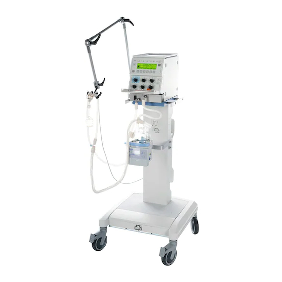
Danger of damage to device or personal injury. Mount the Babylog 8000 plus on the trolley in this position: Tilt the Babylog 8000 plus forwards. Engage the front latches in the slots of the mounting plate. -
Page 17: Inserting The Expiration Valve
Preparation Inserting the expiration valve Inserting the expiration valve Use a sterile expiration valve! Lift the lever upwards to unlock the expiration valve. Slide the expiration valve as far as possible onto the guide rods. Push the lever down again to lock the expiration valve. Fit the silencer on the exhaust nozzle of the expiration valve. -
Page 18: Connecting The Gas Supply
Either: 100 V to 127 V 220 V to 240 V Insert the mains plug of the Babylog 8000 plus into the outlet socket. Breathing gas humidifier – The humidifier must comply with the standard EN ISO 8185. –... -
Page 19: Assembly
Preparation Assembly Assembly Connecting the ventilation hoses WARNING Only use antistatic or non-conductive hoses, to avoid risk to the patient. Only use hose systems that are described here or if they have an internal diameter of at least 10 mm, since the measurement of the airway pressure may otherwise be impaired! Fit the ventilation hoses on the nozzles. -
Page 20: Installing The Bacterial Filter (Optional)
Preparation Assembly When using with Dräger Incubator 8000 or Dräger Incubator Caleo Install the water trap in a vertical position. Mount the holder for the ventilation hoses in the incubator. Press the rubber sleeves of the ventilation hoses into the clamp of the holder. -
Page 21: Installing The Y-Piece And The Flow Sensor
Preparation Assembly Installing the Y-piece and the flow sensor Plug the Y-piece into the ventilation hoses. Plug an ISO 15 flow sensor (84 11 130) into the Y-piece. Use a Y-piece with an integrated flow sensor. Insert the plug of the flow-sensor cable into the flow sensor. Lay the cable along the ventilation hoses to the ventilator. -
Page 22: Before Using For The First Time
Preparation Before using for the first time CAUTION When an extractive monitor is uses, a vacuum may be generated in the airway if the inspiration hose becomes blocked; risk of injury to the patient! For this reason: Connect the sampling line of the extractive monitor only via the adapter with safety valve 84 12 448. - Page 23 Preparation Before using for the first time Display: The unit executes a self-test of its internal memory. All LEDs light and a short continuous tone sounds, followed by a tone sequence. Then Display (example): The software version, the operating hours and optional features are displayed.
-
Page 24: Calibration
Preparation Calibration Calibration For oxygen measurement: – This is done automatically every 24 hours during operation. – It must be done manually each time the sensor is replaced. – It may be done manually at any time. For flow measurement: –... -
Page 25: Calibrating The Flow Sensor
Preparation Calibration To clear the text message on the screen: Press the key »OK«. Calibrating the flow sensor – This must be done each time the ventilator is switched on, – each time the sensor is assembled for use and –... - Page 26 Preparation Calibration Calibration: Press the keys »Cal. Config.« and » -Cal«. Remove the tube connector and seal the patient side of the Y-piece with, for example, a sterile glove. No gas may flow through the Y-piece during calibration (since the zero point is calibrated). Display: Press the key »Start«.
-
Page 27: Replacing The Insert Of The Flow Sensor
Preparation Calibration Replacing the insert of the flow sensor This must be done if the following message is displayed: Flow measurement disturbed Measurement switched off Disconnect the plug from the flow sensor. Press the buttons on both sides and simultaneously pull the insert out of the Y-piece. -
Page 28: Checking The Unit
A copy of this checklist should be available next to the ventilator. Tick off the items in this checklist next to the ventilator with a pencil and then sign it and enter the date. Checklist for Babylog 8000 plus 5.n Date: Knowledge of the Instructions for Use is essential. - Page 29 Preparation Checking the unit What Check Minute volume Select ventilation mode »IPPV/IMV« and set the lower MV alarm limit to 1 L/min. MV low and audible alarm Display (after max. 30 seconds) Reset lower and upper MV alarm limits to the specified values.
-
Page 31: Operation
Operation Operation Putting into service ..........33 Set PEEP to <2.5 mbar . - Page 32 Operation Displaying curves and measured values ....... 57 Airway pressure curve Paw ......... . . 57 Displaying the flow curve .
-
Page 33: Putting Into Service
Operation Putting into service Operation Putting into service Switch on the ventilator by pressing the mains switch on the rear until it locks in position. Calibrate the flow sensor (page 25). Before connecting, set the following rotary knobs specifically for each patient: »Insp. -
Page 34: Set Peep To <2.5 Mbar
Operation Putting into service Set PEEP to <2.5 mbar Pull the PEEP knob and turn it anticlockwise into the area marked in red. Set the desired PEEP. Connect to the patient. Estimate the necessary tidal volume VT. Recommendation: about 5 to 6 mL/kg body weight. Regular routine Top up the breathing gas humidifier with distilled water. -
Page 35: Overview Of The Ventilation Modes
Operation Overview of the ventilation modes Overview of the ventilation modes The Babylog 8000 plus can operate in five different ventilation modes, which can also be modified by activating additional functions. Ventilation modes Additional functions IPPV/IMV Intermittent Positive Pressure Ventilation/... -
Page 36: Selecting The Ventilation Mode And Additional Functions
IPPV/IMV to SIMV with volume guarantee VG. Press the key »Vent. Mode«. Press the key »SIMV«. For the time being, the Babylog 8000 plus continues to run in IPPV/IMV mode. The trigger volume can be adjusted with the keys »... -
Page 37: Setting The Trigger Volume (Trigger Sensitivity)
Set the desired tidal volume VTset with the keys » « or » «. Press the key »On«. The Babylog 8000 plus now operates in SIMV mode with volume guarantee. Exit from the menu: Press the key » «. Switching off the additional function VG: Press the key »Vent. -
Page 38: Ippv/Imv
Operation IPPV/IMV IPPV/IMV Intermittent Positive Pressure Ventilation Intermittent Mandatory Ventilation Time-controlled, pressure-limited ventilation with a predeter- mined pattern for patients without spontaneous breathing – with or without pressure plateau. Switching on IPPV/IMV Press the keys »Vent. Mode«, »IPPV/IMV«, »On«. IPPV/IMV can be combined with: –... -
Page 39: Ventilation Without A Pressure Plateau
Operation IPPV/IMV Displaying the flow curve: Press the keys »Graph« and »Flow«. Exit from the menu: Press the key » «. Displaying the measured pressure values: Press the keys »Meas« and »Paw«. Use the rotary knobs »P «, »PEEP/CPAP«, »T «, »T «... - Page 40 Operation IPPV/IMV Displaying the pressure curve: Press the keys »Graph« and »Paw«. Press the key » «. Use the rotary knobs »PEEP/CPAP«, »T «, »T « and »Insp. Flow « to set the desired ventilation pattern. Displaying the flow curve: Press the keys »Graph«...
-
Page 41: Sippv
Operation SIPPV SIPPV Synchronized Intermittent Positive Pressure Ventilation Ventilation with a predetermined pattern, synchronised with the patient's spontaneous breathing. The patient determines the insp ventilation frequency. If the patient suffers apnoea, ventilation is executed at the frequency determined by T and T PEEP Flow... -
Page 42: Simv
Operation SIMV SIMV Synchronized Intermittent Mandatory Ventilation Ventilation with a predetermined pattern or predetermined frequency, synchronised with the patient's spontaneous insp breathing. The patient can breathe spontaneously between the synchronised ventilation strokes, but does not receive pressure support. This mode is useful for weaning the patient from ventilation. PEEP If the patient suffers apnoea, ventilation is executed at the frequency determined by T... -
Page 43: Psv
Operation Pressure Support Ventilation Pressure-supported ventilation synchronised with the patient's own breathing. The patient determines the duration of the insp inspiration and the ventilation frequency. The ventilation stroke is terminated when the inspiratory flow drops to about 15 % of the peak flow or, at the latest, after T This mode is intended for spontaneously breathing patients with sufficient regulation of their breathing who are to be supported with an adjustable inspiratory pressure. -
Page 44: Cpap
Operation CPAP CPAP Continuous Positive Airway Pressure The Babylog 8000 plus applies a continuous flow and adjusts the airway pressure to the PEEP/CPAP level. Press the keys »Vent. Mode«, »CPAP« and »On«. Combining CPAP with: – separate expiratory flow VIVE: see page 49. -
Page 45: Cpap With Nasopharyngeal Tube
Operation CPAP CPAP with nasopharyngeal tube Due to the leakage from the patient's mouth, it is not possible to monitor the minute volume or to check for apnoea. Therefore either switch off flow measurement: Remove plug from Y-piece set lower MV alarm limit to »0« and set apnoea time to »OFF«... -
Page 46: Volume Guarantee Vg (Optional)
Operation Volume guarantee VG (optional) Volume guarantee VG (optional) This can be combined with the ventilation modes SIPPV, SIMV and PSV. insp The inspiratory plateau pressure is automatically regulated between P and PEEP such that the set tidal volume VTset insp is applied. -
Page 47: High-Frequency Ventilation Hfv (Optional)
Operation High-frequency ventilation HFV (optional) High-frequency ventilation HFV (optional) High-frequency ventilation around the PEEP/CPAP level, which acts as the mean pressure. The high-frequency pulses are superimposed at the selected frequency around the mean pressure. Suitable for patients with a body weight of up to about 2 kg, for ventilating with reduced stress on the lungs. -
Page 48: High-Frequency Ventilation With Imv
Operation High-frequency ventilation with IMV High-frequency ventilation with IMV This is a combination of high-frequency ventilation and intermittent expansion strokes. insp During the HF oscillations, the mean pressure is that set for PEEP/CPAP. The high-frequency pulses are superimposed at the selected frequency over the mean pressure. -
Page 49: Separate Expiratory Flow Vive
Operation Separate expiratory flow VIVE Separate expiratory flow VIVE VIVE (Variable Inspiratory and Variable Expiratory Flow) The continuous expiratory flow can be adjusted inde- pendently of the continuous inspiratory flow . The inspira- insp tory flow is effective during ventilation strokes, while the expira- tory flow is effective during spontaneous breathing phases and in CPAP mode. -
Page 50: Setting Alarm Limits
Operation Setting alarm limits Setting alarm limits The alarm limits for monitoring of the following parameters are set automatically: Upper alarm limit Pinsp + 5 mbar Airway pressure Pinsp Upper alarm limit for ΔP ventilation strokes: + 5 mbar insp Upper alarm limit for Disconnection PEEP + ΔP/4... - Page 51 Operation Setting alarm limits In the monitoring menu, press the key » «. Display (example): Select the desired alarm parameter with the key » «. Adjust to the desired value with the keys » « or » «. Repeated short depressions of the keys adjust the value in single steps.
-
Page 52: Starting Inspiration Manually
Operation Starting inspiration manually Starting inspiration manually This function is active in any ventilation mode, regardless of the T and T settings. All other parameter settings remain effective. Limit the inspiration pressure with the rotary knob »P «. insp Press and hold the key »man. Insp.« for as long as the inspiration is to last, for example for X-ray examination of the thorax with maximum inspiration. -
Page 53: Nebulizing Medicaments (Optional)
Before medicament nebulizing Remove plug from the flow sensor. Acknowledge the warning message on the Babylog 8000 plus. When using the separate flow sensor ISO 15 (84 11 130): Detach the flow sensor from the Y-piece and plug the tube catheter cone into the Y-piece. -
Page 54: Pneumatic Medicament Nebulizer 84 11 030
Operation Nebulizing medicaments (optional) Pneumatic medicament nebulizer 84 11 030 Prerequisite: Compressed air connection on the rear of the unit and conversion kit 84 11 025 Preparation Install the coupling: On the left side of the ventilator, remove the lower securing screw of the case with a coin and secure the coupling under this screw. -
Page 55: Starting Nebulization
Operation Nebulizing medicaments (optional) Starting nebulization Insert the plug of the supply line into the socket and press it in until it locks. CAUTION Features of medicament nebulization The nebulizer nebulizes continuously, but the aerosol resulting FiO generate during expiration does not enter the lungs. [Vol.%] Since the nebulizer is driven by medical air, the oxygen concentration FiO... -
Page 56: Active Medicament Nebulizer "Aeroneb Pro" (Mp 01 010)
Additional monitors must be used. Re-insert the flow sensor after nebulization. Do not activate the nebulizer function on the Babylog 8000 plus. Because the unused nebulizer flow is taken into account during volume delivery, the ventilator would deliver an insufficient volume. -
Page 57: Displaying Curves And Measured Values
Operation Displaying curves and measured values Displaying curves and measured values Airway pressure curve Paw In the monitoring menu, press the keys »Graph« and »Paw«. Display (example): Pressure axis scale (50 mbar) Pressure limit »P « (dotted horizontal line) insp Time axis scale (2 s) End of selected expiration time T (dotted vertical line) -
Page 58: Freezing Curves
Operation Displaying curves and measured values Freezing curves In the sub-menu »Graph«, press the key »Freeze«. Cancelling the freeze function: Press the key »Freeze« again. Continuous monitoring of the curve is resumed. Exit from the menu: Press the key » «. -
Page 59: Displaying Lung Values
Operation Displaying curves and measured values Displaying lung values The Babylog 8000 plus calculates the resistance and compli- ance of the patient's lung using linear regression analysis. In the monitoring menu, press the keys »Meas« and »RC«. = resistance of the airway, including the tube... -
Page 60: Combinations Of Measured Values
Operation Displaying curves and measured values Combinations of measured values In the monitoring menu, press the keys »Meas« and »MV O P«. Display (example): = expiratory minute volume = measured inspiratory oxygen concentration Mean = mean value of the airway pressure of the preceding breathing cycle Exit from the menu: Press the key »... -
Page 61: Displaying All Settings
Operation Displaying curves and measured values Displaying all settings In the monitoring menu, press the key »Values«. All settings are displayed. Display (example): To display further settings: Press the key »Set2«. Displaying all measured values Press the key »Meas1« or »Meas2«. All measured values are displayed in the two windows. -
Page 62: Displaying Trends
Operation Displaying trends Displaying trends The trends of some of the measured values over the preceding 24 hours are stored in the trend memory, namely: Inspiratory oxygen concentration Mean Mean pressure Minute volume Dynamic compliance Resistance RVR* Rate Volume Ratio the ratio breathing rate (frequency): tidal volume (see page 128) In the monitoring menu, press the key »Trend«. -
Page 63: Messages
Operation Messages Messages Messages are displayed in a hierarchical order based on their importance. For example, if two messages are triggered simul- taneously, the message for the more critical condition will be displayed first. Messages which require confirmation will also be superimposed by alarms with a higher priority. -
Page 64: Reading The Log
Operation Reading the log Suppressing the message and audible signal for about 30 seconds: Press the key »OK«. Each message is automatically recorded in the log of the ventilator. Suppressing the warning/alarm tone for 2 minutes Press the key » «. CAUTION While the warning/alarm tone is suppressed for 2 minutes, new messages will still be displayed,... -
Page 65: Configuration
Operation Configuration Configuration Setting time and date Press the keys »Cal. Config.«, »Config« and »Clock«. Use the keys » « and » « to highlight the parameter to be changed. (Example: 02) Adjust the value with the keys » « and » «. -
Page 66: Adjusting The Screen Contrast
Operation Configuration Adjusting the screen contrast This can be done only on units with an LCD screen. The screen contrast can be optimised to suit the user's viewing angle. Press the keys »Cal. Config.«, »Config« and »Contr«. Display (example): A test pattern is displayed on the screen. Adjust the contrast with the keys »... -
Page 67: Analogue And Digital Interfaces (Optional)
The connected devices should be installed in the same room as the Babylog 8000 plus, and not less than 1.5 metres away from the patient.* Each of the two analogue outputs transmits one of the avail- able measured values. -
Page 68: Signal From Pulse Output
Other printers should be used only after consultation with Dräger Medical. Connect the printer via a cable 83 06 489. NOTE The RS 232 interfaces of the printer and the Babylog 8000 plus must be configured identically. Configuring the RS 232 interface: see page 75. -
Page 69: Printing Reports
Press the key »Print«. Display (example): Printing reports This function is used for documenting measured values, settings and the status of the ventilator. Example: +--------------------------------------------------------------------------------+ |15:39 23.08.1997 IPPV Babylog 8000 plus |Settings: Measurements: |TI: 0.40 s Pinsp: 25.0 mbar FiO2: 21 % Mean: 10.1 mbar |... -
Page 70: Printing A Trend
Operation Analogue and digital interfaces (optional) To print a report automatically every 30 minutes: Press the key »Select« repeatedly until »30 min. report« is highlighted. Start printing by pressing the key »Start«. The function of this key then changes to »Stop«. Printing a trend This function is used for graphical printing of the measured values for Mean, MV and FiO... -
Page 71: Printing Curves
Operation Analogue and digital interfaces (optional) To cancel the printing operation: Press the key »Stop«. Printing curves This function is set for graphical printing of the curves: – airway pressure, – flow and – tidal volume Press the key »Select« repeatedly until »Graphics« is highlighted. -
Page 72: Printing Everything
Operation Analogue and digital interfaces (optional) Printing everything This function is used to print the report, the trends and the curves. Press the key »Select« repeatedly until »All« is highlighted. Start printing by pressing the key »Start«. The function of this key then changes to »Stop«. To cancel the printing operation: Press the key »Stop«. -
Page 73: Transmitting Data To A Patient Monitor
Operation Transmitting data to a patient monitor Transmitting data to a patient monitor This function is set for connection of a device (monitor, PC) which uses the BabyLink transmission protocol. For more details, see the "BabyLink" manual. Connect the monitor via a cable 83 06 488. Press the key »Select«... - Page 74 Operation Transmitting data to a patient monitor The following signals and scales can be selected: Airway pressure –10… 90 mbar → 0…10 V Airway pressure –5… 45 mbar → 0…10 V → 0…10 V Mean airway pressure –10… 90 mbar Mean airway pressure –5…...
-
Page 75: Configuring Pulse Output
Operation Transmitting data to a patient monitor To select the default settings during operation: Press the key » /P«. If a measured value exceeds the scale limits, the voltage is limited to the end-of-scale value. The setting remains stored even if the ventilator is switched off. Configuring pulse output Press the key »Param«... -
Page 76: Setting The Printer
Press the key » «. The settings remain stored even if the ventilator is switched off. Setting the printer The printer must be configured as follows: Baudrate same as Babylog 8000 plus Parity none Data bits Handshake mode XON/XOFF Alternate control sequence mode Shutting down After disconnecting the patient. -
Page 77: Fault - Cause - Remedy
Fault – Cause – Remedy Fault – Cause – Remedy Fault – Cause – Remedy ......... . . 78... - Page 78 Fault – Cause – Remedy Fault – Cause – Remedy The Babylog 8000 plus classifies the messages in three levels of urgency: Alarm messages – Caution messages – Advisory messages The messages are listed in alphabetical order in the following table.
- Page 79 Fault – Cause – Remedy Message Cause Remedy Hose kinked? Ventilation hose kinked or blocked or Check and clear the hose system. condensate in the hose. Internal diameter of ventilation hoses too Use a suitable hose system. small. I : E maximum 3 : 1! The rotary knobs for T and T have been...
- Page 80 Replace the cable. RS 232 interface or printer configured Configure the RS 232 interface of the incorrectly. printer and the Babylog 8000 plus with identical settings. Re-calibrate flow sensor if During operation: flow sensor has been Press »OK« and calibrate the sensor exchanged! replaced.
-
Page 81: Care
Care Care Safety information on care ......... . 82 Stripping down . -
Page 82: Safety Information On Care
Remove the hoses from the sleeves on the ventilator and on the humidifier module. Remove the water trap and the Y-piece and pull the collecting jar from the water trap. Removing the expiration valve Lift the locking lever upwards. Pull the expiration valve out forwards. Babylog 8000 plus... -
Page 83: Reprocessing Methods
Care Reprocessing methods Reprocessing methods Classification of medical devices For reprocessing, the medical devices are classified according to their type of application and the resulting risks: – Non-critical medical devices: Surfaces accessible to the operator, e.g., device surfaces, cables – Semi-critical medical devices: Breathing-gas conveying parts, e.g., ventilation hoses, masks Cleaning and disinfection methods... -
Page 84: Testing Of Methods And Agents
Care Reprocessing methods Testing of methods and agents The cleaning and disinfection of the medical devices were tested using the following methods and agents. At the time of testing, the methods and agents showed good material compatibility and effectiveness. Manual cleaning and disinfection Non-critical medical devices Semi-critical medical devices Manual cleaning... -
Page 85: Visual Inspection
Care Reprocessing methods Carrying out manual disinfection Sterilisation Disinfect items by immersing. During sterilisation, living microorganisms are removed from After the contact time has elapsed, rinse the items under semi-critical medical devices. Residual water in the interior running water until disinfectant residue is no longer areas of the items is also dried out. -
Page 86: Reprocessing List
Non-critical medical devices Items which can be reprocessed Recommended Manual reprocessing Cleaning Disinfection intervals Basic Babylog 8000 plus unit Per patient Trolley Per patient Flow sensor cable Per patient Gas connection hoses Per patient Semi-critical medical devices... -
Page 87: Assembly
Care Assembly Assembly Installing the flow-sensor insert Align the two marks and slide the insert into the Y-piece until it locks into position. Insert the plug into the sensor. Assemble the equipment as described in "Preparation" (page 16 to page 22). After switching on: Calibrate the flow sensor (page 25) Check readiness for use (page 88). -
Page 88: Checking Readiness For Use
Care Checking readiness for use Checking readiness for use This must be done each time the unit is assembled. Assemble the equipment completely (page 19). After switching on, calibrate the flow sensor (page 25). Connecting the test lung The test lung consists of a bellows simulating compliance (about 0.5 mL/mbar) and a CH 12 tracheal tube about 165 mm long, with connector, for simulation of airway resistance. -
Page 89: Testing Gas Failure Alarm
Care Checking readiness for use Testing gas failure alarm Switch on the ventilator by pressing the main switch on the rear of the unit until it locks into position. Switch on IPPV/IMV (page 38). Set lower alarm limit MV to 0 and upper alarm limit to 15 L/min. -
Page 90: Testing Ippv
Care Checking readiness for use Testing IPPV Switch on IPPV/IMV (page 38). Set the following rotary knobs (where the green LEDs are lit) as follows: »O -Vol%« to 21. »Insp. Flow « to 10. »T « to 0.4 »T « to 0.6 »P «... -
Page 91: Testing Alarm Limits
Care Checking readiness for use Testing alarm limits Alarm limits for apnoea: Switch on CPAP (page 44). After not more than 30 seconds: The red alarm lamp must blink and the alarm must sound. Display (example): Apnoea MV low Alarm limits for airway pressure: Switch on IPPV/IMV (page 38). - Page 92 Check setting! Set the rotary knob »PEEP/CPAP« back to 0. Connect the test lung again. If it passes all of the above tests the Babylog 8000 plus is ready for use! Test the humidifier as described in the related Instructions for Use!
-
Page 93: Maintenance Intervals
Care Maintenance Intervals Maintenance Intervals Always clean and disinfect the unit and/or its components before maintenance and before sending it/them in for repair. sensor replace in the case of a fault message (page 17). Cooling-air filter clean or replace every 4 weeks (page 94); to be replaced at least once per year. -
Page 94: Replacing The Cooling-Air Filter
Dräger Medical. Disposal of the ventilator – at the end of its service life The Babylog 8000 plus 5.n may be returned to Dräger Medical for suitable disposal. For countries subject to the EU directive 2002/96/EC: This device is subject to EU Directive 2002/96/EC (WEEE). It is... -
Page 95: What's What
What's What What's What Front control panel ..........96 Display panel . -
Page 96: Front Control Panel
What's What Front control panel What's What Front control panel Rotary knob for inspiratory O concentration »O -Vol%« Rotary knob »Insp. Flow « Rotary knob »Inspiration time T « Rotary knob for limiting inspiration pressure »P « insp Rotary knob »Expiration time T «... -
Page 97: Display Panel
What's What Display panel Display panel Key »Cal. Config.« for selecting the calibration and configuration menus Yellow LED »Trigger« lights when inspiration is started by the trigger Screen for display of settings and measured values Bargraph display for the airway pressure Paw Red alarm lamp;... -
Page 98: Connections
What's What Connections Connections Silencer "EXHAUST" Locking lever for expiration valve Expiration nozzle "GAS RETURN" Inspiration nozzle "GAS OUTPUT"... -
Page 99: Rear Side
What's What Rear side Rear side Main switch Mains fuses (2 x) Potential equalisation stud Oxygen connection "INFLATING GAS INPUT" Medical-air connection "INFLATING GAS INPUT" Socket for flow-sensor cable Cooling-air filter for fan Connectors for optional interfaces... -
Page 101: Technical Data
Technical Data Technical Data Ambient conditions ..........102 Parameters –... -
Page 102: Ambient Conditions
Technical Data Ambient conditions Technical Data Ambient conditions During operation: Temperature 10 to 40 °C Atmospheric pressure 780 to 1060 hPa Relative humidity 30 to 90 %, no condensation For storage: Temperature –20 to 60 °C Atmospheric pressure 500 to 1060 hPa Relative humidity 10 to 95 %, no condensation Parameters –... -
Page 103: Equipment Parameters
Technical Data Equipment parameters Equipment parameters Principle of operation Babylog 8000 plus ventilates on the continuous-flow principle with time control and and is pressure limited. Oxygen is added to the air with an integrated air-oxygen mixer. Control principle Continuous flow, expiration valve, pressure-limited, time-controlled Trigger sensitivity 1 to 10 corresponds to about 0.02 to 3 mL... -
Page 104: Flow And Volume
Technical Data Flow and volume Flow and volume Sensor Hot-wire anemometer between Y-piece and tube connector Sensor type Dead space volume (without tube) Resistance at 30 L/min ≤12 mbar Y-piece with flow sensor 84 10 185 1.7 mL ≤11 mbar Flow sensor: ISO 15 84 11 130 0.9 mL... -
Page 105: Inspiratory Oxygen Concentration
Measuring accuracy ±3 Vol.% referred to the medical gases oxygen and air. During calibration, Babylog 8000 plus expects these to contain 20.9 Vol.% of oxygen and 100 Vol.% of oxygen, respectively. The measured value is displayed numerically on the screen. -
Page 106: Alarm Criteria
An alarm is generated if the airway pressure drops below Safety principle PEEP/CPAP –2 mbar and the pressure-time integral exceeds The Babylog 8000 plus is a software-controlled ventilator. 6 mbar•s. Its safety concept is based on the use of two microprocessor... -
Page 107: Operating Data
Technical Data Operating data Operating data Mains supply voltage Range: 100/110/127 V 220/240 V switchable 50/60 Hz Current consumption at 230 V 0.8 A at 110 V 1.3 A Power consumption approx. 140 W Fuses Range 100 to 127 V T4A H 250 V IEC 127-2/ V Range 230 to 240 V T4A H 250 V IEC 127-2/ V... - Page 108 Connection plug SMB-Subclic Signal delay Electronic filter circuits in the Babylog 8000 plus delay the signals for airway pressure and flow by about 15 ms with respect to the sensor signals. This delay must be taken into account when measuring with a separate measuring device and comparing its output with the analogue output of the Babylog 8000 plus.
-
Page 109: Emc Declaration
Technical Data EMC Declaration EMC Declaration General information The EMC compliance of the medical device is also applicable to the external cables, transducers, and accessories specified in the list of accessories. In addition, accessories which do not affect EMC compliance may be used if no other reasons forbid their use (see other sections of the Instructions for Use). - Page 110 Technical Data EMC Declaration Electromagnetic environment The medical device is intended for use in an electromagnetic environment as specified below. The user must ensure its use in such an environment. Emissions Compliance according to Electromagnetic environment Radio frequency emissions Group 1 The medical device uses RF energy only (CISPR 11) for its internal function.
- Page 111 Technical Data EMC Declaration Electromagnetic immunity The medical device is intended for use in an electromagnetic environment as specified below. The user must ensure its use in such an environment. Immunity against Test level Compliance level Electromagnetic (IEC 60601-1-2) (medical device) environment Electrostatic discharge Contact discharge:...
- Page 112 Technical Data EMC Declaration Immunity against Test level Compliance level Electromagnetic (IEC 60601-1-2) (medical device) environment Conducted RF 150 kHz to 80 MHz: 10 V Recommended mini- (IEC 61000-4-6) 10 V inside ISM bands** mum distance to porta- ble and mobile RF trans- 150 kHz to 80 MHz: 3 V mitters with transmission outside ISM bands...
-
Page 113: Description
Description Description Pneumatic circuits ..........114 Gas supply . -
Page 114: Pneumatic Circuits
Description Pneumatic circuits Description Pneumatic circuits Inspiration Expiration Sintered filter 15 Pneumatic control valve Non-return valve 16 Pneumatic safety valve Pressure regulator 17 Relative-pressure sensor Absolute-pressure sensor 18 Electrical PEEP control valve Solenoid valve of mixer and dosing unit 19 Safety valve Flow adjuster of mixer and dosing unit 20 Expiration valve Solenoid changeover valve... -
Page 115: Gas Supply
Description Pneumatic circuits Inspiration Expiration Gas supply Controlled ventilation The compressed gases air and oxygen are connected via the There is a continuous flow of gas through the inspiration hose filters 1 and the non-return valves 2 to the pressure to the Y-piece. -
Page 116: Peep
Description Pneumatic circuits Inspiration Expiration Air is first connected to the pneumatic valve 12 via the solenoid PEEP valve 7, the solenoid valve 8 and the solenoid valve 9. The PEEP control valve 18 generates a control pressure on the The pneumatic valve 12 closes the connection between the control side of the expiration valve 20. -
Page 117: Ventilation Mode
Ventilation mode Ventilation mode Continuous Positive Airway Pressure (CPAP) The Babylog 8000 plus maintains the airway pressure at the PEEP/CPAP level. The patient can breathe spontaneously at any time. The continuous flow setting should be clearly higher than that required by the patient for spontaneous breathing in order to avoid variations of the airway pressure and the related increased breathing effort. -
Page 118: Synchronized Intermittent Positive Pressure Ventilation (Sippv)
T insp The shape of the ventilation stroke is set just as for IPPV/IMV. The Babylog 8000 plus detects the spontaneous inspiration by flow measurement. A ventilation stroke is triggered if – inspiratory flow is detected after an expiration and –... -
Page 119: Synchronized Intermittent Mandatory Ventilation (Simv)
Description Ventilation mode Synchronized Intermittent Mandatory Ventilation (SIMV) SIMV combines synchronised ventilation with spontaneous breathing. In contrast to SIPPV, support is not provided for each spontaneous inspiration, but only for a sufficient number to ensure that ventilation is executed with the set frequency. Between the ventilation strokes, the patient can breathe spontaneously, but receives no support from the ventilator. -
Page 120: Pressure Support Ventilation (Psv)
Description Ventilation mode Pressure Support Ventilation (PSV) The PSV mode operates in a manner which is basically similar to SIPPV. In addition to the breathing frequency, however, the patient also controls the duration of the ventilation stroke via the flow in this mode. The mandatory inspiration is terminated when the flow drops to 15 % of the maximum inspiratory flow, or after the time T , whichever occurs first. -
Page 121: Additional Functions
2. the inspiratory pressure pattern does not have a plateau because the flow is too low or T is too short. In both cases, the Babylog 8000 plus displays a warning message if the actual VT lies below 90 % of the desired volume. -
Page 122: High-Frequency Ventilation (Hfv)
Description Additional functions If the flow sensor fails, or if the patient stops breathing sponta- neously, mandatory ventilation is started as in IPPV/IMV mode. High-Frequency Ventilation (HFV) Ventilation with high-frequency pressure oscillations permits gas exchange in the lungs in spite of the very small tidal volumes –... -
Page 123: Hfv With Imv
Description Additional functions HFV with IMV The high-frequency oscillations are superimposed on the PEEP/CPAP pressure during the expiration time T between the IMV strokes. They stop 100 milliseconds before an IMV insp stroke and start again 250 milliseconds after the stroke. The delay after the stroke is intended to ensure sufficient time for expiration and to avoid airtrapping. -
Page 124: Monitoring Functions
Comprehensive laboratory tests have shown that the inspira- tory leg of all commonly used hose systems accounts for about 70 % of the total resistance. The Babylog 8000 plus therefore uses this estimate for calculations: – 0.7 • <P –... -
Page 125: Measurement Of Flow And Volume
If the tube is not a tight fit, some air will often escape between the wall of the trachea and the tube. Since the flow sensor of the Babylog 8000 plus is located in the Y-piece, i.e. upstream of the leak, breathing gas is lost after measurement during inspiration and before measurement during expiration. -
Page 126: Trigger Function
Description Monitoring functions Trigger function The Babylog 8000 plus detects spontaneous breathing by measuring the flow. When the patient attempts to breath in, the flow signal, which was until then zero or negative (= expiration), starts to rise. In order to reliably detect inspira-... -
Page 127: Measuring Lung Parameters
The time constant of the respiratory system (TC = R•C) – The overdistension index, calculated in accordance with [*] The Babylog 8000 plus 5.n first stores all measured values Paw(t), flow(t) and V(t) for one ventilation stroke with a maximum duration of 5 seconds. 120 measured values are taken per second. -
Page 128: Rate-Volume Ratio (Rvr)
The ratio of the breathing rate to the tidal volume can help to assess the chances of successfully weaning the patient from the ventilator**. The Babylog 8000 plus calculates and displays the RVR. In order to avoid fluctuations of the measured value... -
Page 129: Explanation Of Abbreviations
Description Explanation of abbreviations Explanation of abbreviations Abbreviation Meaning Abbreviation Meaning Compliance Maximum inspiration pressure insp CPAP Continuous Positive Airway Pressure Resistance Breathing Trigger Response Time Transport coefficient which describes the Rate-Volume Ratio transport of CO out of the lungs SIPPV Synchronized Intermittent Positive Frequency... -
Page 130: Explanation Of Symbols On The Screen And Keys
Description Explanation of symbols on the screen and keys Explanation of symbols on the screen and keys Symbols Explanation Symbols Explanation Caution: observe accompanying documents Main switch I /0 Potential equalisation stud Menu for setting the minute-volume alarm limits Upper alarm limit Lower alarm limit Menu for the log Reduce or scroll backwards... -
Page 131: Parts List/Order List
Parts List/Order List Parts List/Order List Parts List ............132 Order List . - Page 132 37, 37a Item No. Designation/description Order No. Item No. Designation/description Order No. 1 – 9 Babylog 8000 plus 5.n, basic unit 84 09 200 15.1 Temperature/flow sensor for hose (see Order List for other versions) 0.75 m 84 18 507...
- Page 133 Parts List Item No. Designation/description Order No. Silicone hose K, 0.35 m 84 03 070 Double cone, 11a 84 09 897 Adapter dia. 15 / dia. 15 84 18 407 Temperature/flow sensor adapter 84 18 455 Corrugated hose, flexible 84 10 709 Adapter 22f/22m+15f for single-use chamber 84 18 289...
- Page 134 Order List Designation/description Order No. Designation/description Order No. Babylog 8000 plus 5.n, basic unit Hinged arm for use outside an incubator, Optional voltages: with mounting for hinged arm 84 09 609 100 V to 127 V / 220 V to 240 V...
- Page 135 84 10 816 Hose set HFV, Fisher & Paykel 84 11 153 Hose (light) 0.65 m 84 10 814 Expiration valve, Babylog 8000 plus 84 08 950 Hose (light) 1.00 m 84 10 815 Neonatal flow sensor Y-piece 84 10 185 Hose (light) 1.20 m...
-
Page 136: Index
Index Index Abbreviations ........129 High-frequency ventilation ....20 Advisory messages . - Page 137 Index Safety ......... . 5 Screen layout .
- Page 138 These Instructions for Use apply only to Babylog 8000 plus 5.n with Serial No.: If no Serial No. has been filled in by Dräger Medical these Instructions for Use are provided for general information only and are not intended for use with any specific machine or device.