Table of Contents
Advertisement
Quick Links
Advertisement
Table of Contents
Troubleshooting

Related Manuals for Canon iPF9000 series


Summary of Contents for Canon iPF9000 series
-
Page 1: Service Manual
Service Manual iPF9000 series Aug 8 2007... - Page 3 Canon will release technical information as the need arises. In the event of major changes in the contents of this manual over a long or short period, Canon will issue a new edition of this manual.
-
Page 4: Symbols Used
Introduction Symbols Used This documentation uses the following symbols to indicate special information: Symbol Description Indicates an item of a non-specific nature, possibly classified as Note, Caution, or Warning. Indicates an item requiring care to avoid electric shocks. Indicates an item requiring care to avoid combustion (fire). Indicates an item prohibiting disassembly to avoid electric shocks or problems. - Page 5 Introduction The following rules apply throughout this Service Manual: 1. Each chapter contains sections explaining the purpose of specific functions and the relationship between electrical and mechanical systems with refer- ence to the timing of operation. In the diagrams, represents the path of mechanical drive; where a signal name accompanies the symbol , the arrow indicates the direction of the electric signal.
-
Page 7: Table Of Contents
Contents Contents Chapter 1 PRODUCT DESCRIPTION 1.1 Product Overview ............................1- 1 1.1.1 Product Overview ..............................1- 1 1.2 Features ..............................1- 3 1.2.1 Features .................................. 1- 3 1.2.2 Features .................................. 1- 3 1.2.3 Features .................................. 1- 3 1.2.4 Printhead ................................. 1- 3 1.2.5 Ink tank .................................. - Page 8 Contents 1.7.3.3 Precautions against Static Electricity ............................. 1- 85 1.7.3.4 Precautions for Disassembly/Reassembly..........................1- 85 1.7.3.5 Self-diagnostic Feature ................................1- 85 1.7.3.6 Disposing of the Lithium Battery ............................1- 85 Chapter 2 TECHNICAL REFERENCE 2.1 Basic Operation Outline ..........................2- 1 2.1.1 Printer Diagram................................2- 1 2.1.2 Printer Diagram................................2- 1 2.1.3 Print Signal Sequence .............................2- 3...
- Page 9 Contents 2.4.6.1 Maintenance cartridge relay PCB components........................2- 56 2.4.7 Power Supply ................................ 2- 56 2.4.7.1 Power supply block diagram ..............................2- 56 2.5 Detection Functions with Sensors ......................2- 57 2.5.1 Sensors for covers..............................2- 57 2.5.2 Ink passage system............................... 2- 58 2.5.3 Carriage system ..............................
- Page 10 Contents 4.3.15 Opening and closing ink supply valves ........................4- 29 4.3.16 Draining the ink ..............................4- 30 4.4 Applying the Grease ..........................4- 31 4.4.1 Applying the Grease ..............................4- 31 4.5 Adjustment and Setup Items ........................4- 34 4.5.1 Adjustment Item List ..............................4- 34 4.5.2 Action to take after replacing the Carriage Unit or Multi Sensor ................4- 34 4.5.3 Action to take after replacing the Feed Roller Encoder or Feed Roller..............4- 34 4.5.4 Action to take after replacing the Head Management Sensor ................4- 34...
- Page 11 Contents 6.1.3.17 03800204-2540/03830201-2541/03830202-2542/03830203-2543/03830212-2544/03830213-2545/03830206-2546/ 03830205-2548/03830215-2549/03830207-254A/03830209-254B/03830208-254C Invalid ink tank ID........6- 7 6.1.3.18 03830304-2560/03830301-2561/03830302-2562/03830303-2563/03830312-2564/03830313-2565/03830306-2566/ 03830305-2568/03830305-2568/03830315-2569/03830307-256A/03830309-256B/03830308-256C Ink tank EEPROM error ... 6- 7 6.1.3.19 03810204-2570/03810201-2571/03810202-2572/03810203-2573/03810212-2574/03810213-2575/03810206-2576/ 03810205-2578/03810215-2579/03810207-257A/03810209-257B/03810208-257C Ink low error (occurs when replacing the printhead) ....................................... 6- 7 6.1.3.20 03810204-2580/03810201-2581/03810202-2582/03810203-2583/03810212-2584/03810213-2585/03810206-2586/ 03810205-2588/03810215-2589/03810207-258A/03810209-258B/03810208-258C Ink low error (occures when cleaning B is executed)......................................
- Page 12 Contents Chapter 7 SERVICE MODE 7.1 Service Mode ............................. 7- 1 7.1.1 Service Mode Operation ............................7- 1 7.1.2 Map of the Service Mode ............................7- 2 7.1.3 Map of the Service Mode ............................7- 9 7.1.4 Map of the Service Mode ............................7- 16 7.1.5 Details of Service Mode ............................7- 23 7.1.6 Details of Service Mode ............................7- 32 7.1.7 Details of Service Mode ............................7- 41...
-
Page 13: Chapter 1 Product Description
Chapter 1 PRODUCT DESCRIPTION... - Page 15 Contents Contents 1.1 Product Overview ................................1-1 1.1.1 Product Overview ..................................1-1 1.2 Features ..................................1-3 1.2.1 Features ......................................1-3 1.2.2 Features ......................................1-3 1.2.3 Features ......................................1-3 1.2.4 Printhead ...................................... 1-3 1.2.5 Ink tank ......................................1-4 1.2.6 Ink tank ......................................1-5 1.2.7 Cutter unit ....................................
- Page 16 Contents 1.7.3.4 Precautions for Disassembly/Reassembly ..............................1-85 1.7.3.5 Self-diagnostic Feature ....................................1-85 1.7.3.6 Disposing of the Lithium Battery ................................. 1-85...
-
Page 17: Product Overview
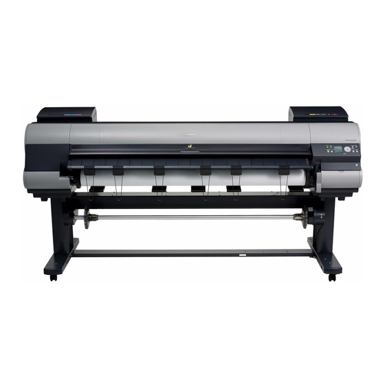
Chapter 1 1.1 Product Overview 1.1.1 Product Overview 0012-6197 iPF9000 / iPF9000S / iPF9100 This printer is a large-format printer that prints in a maximum width of 60 inches with high-speed photographic picture quality. This printer is a stand-mounted type printer and is capable of output to either roll media or cut sheet. [16] [15] [10]... - Page 18 Chapter 1 [2] [1] F-1-2 T-1-1 Upper Cover [13] Stand Ink Tank Cover [14] Maintenance Cartridge Cover Ejection Slot [15] Maintenance Cartridge Ejection Guide [16] Operation Panel Output Stacker [17] Expansion Board Slot Roll Holder Slot [18] Ethernet Port Holder Stopper [19] USB Port Roll Holder...
-
Page 19: Features
Chapter 1 1.2 Features 1.2.1 Features 0012-6215 iPF9000 - Media pass in widths up to 60 inches (1524 mm). - Large ink tanks save the need for their replacement. - Uninterrupted printing from subtanks. - Two kinds of BK inks loaded concurrently to eliminate the need for their replacement. - Hard disk drive mounted for greater ease of job management and for driving on night time. -
Page 20: Ink Tank
Chapter 1 F-1-3 1.2.5 Ink tank 0012-6218 iPF9000 / iPF9100 Ink tanks are disposable. The ink tanks come with 12 colors: mat black (MBK), black (BK), photocyan (PC), cyan (C), photomagenta (PM), magenta (M), yellow (Y), red (R), blue (B), green (G), gray (GY) and photogray (PGY). -
Page 21: Ink Tank
Chapter 1 1.2.6 Ink tank 0017-8112 iPF9000S Ink tanks are disposable. The ink tanks come with 8 colors: mat black (MBK), black (BK), photocyan (PC), cyan (C), photomagenta (PM), magenta (M), yellow (Y) and gray (GY). Each of these inks are pigment ink. The tanks are also available in two capacities: 330 mL and 700 mL. -
Page 22: Cutter Unit
Chapter 1 1.2.7 Cutter unit 0013-6369 iPF9000 / iPF9000S / iPF9100 The cutter unit that mounts on the carriage unit is disposable. Replace the cutter unit when it gets dull. F-1-6 1.2.8 Roll holder 0013-6371 iPF9000 / iPF9000S / iPF9100 The printer comes with a roll holder for paper tubes having an inside diameter of 2 inches as standard. -
Page 23: Media Take-Up Unit
Chapter 1 1.2.10 Media take-up unit 0013-9216 iPF9000 / iPF9000S / iPF9100 Media take-up unit The media take-up unit takes up roll media, ranging in width from 17 to 60 inches, on a 2 or 3-inch paper tube in roll form after they are printed by the host computer. Taking up begins automatically when a sensor attached to the bottom of the stand detects a roll delivered after printing falling down due to the weight of a weight roller. -
Page 24: Hard Disk Drive
Chapter 1 1.2.11 Hard disk drive 0012-6687 iPF9000 Each print job received from the host computer is saved to the 40GB hard disk drive(parallel ATA connection) attached to the printer, so the printer can print the job repeatedly as needed, without having to wait for its retransmission from the host computer. Saving print jobs will offer the following benefits: - Eased computer workload A print job may be automatically preserved to the hard disk when printing or may be preserved to the hard disk without printing. - Page 25 Chapter 1 F-1-13...
- Page 26 Chapter 1 1.2.14 Consumables 0017-8858 iPF9000S Printhead The expendable printhead is the same as the one that comes with the printer. F-1-14 Ink tanks Expendable ink tanks contain 8 colors: mat black, black, photocyan, cyan, photomagenta, magenta, yellow and gray. Each tank is available in two capacities: 330 mL and 700 mL.
-
Page 27: Product Specifications
Chapter 1 1.3 Product Specifications 1.3.1 General Specifications 0012-6224 iPF9000 Type Bubblejet printer (stand model) Feeding system Roll media: Manual (front loading) Cut media: Paper tray (front loading) Feeding capacity Roll media: 1 roll (up to 150 mm outside diameter) Standard roll holder: Paper tube, 50.8 mm (2") inside diameter Cut media: 1 Delivery method... -
Page 28: Product Specifications
Chapter 1 Operating noise Operating: Approx. 52dB (A) or less Idle: Approx. 35dB (A) or less Operating environment Operating temperature: 5oC to 35oC Relative humidity: 10% to 90%RH Print quality guaranteed Guaranteed print quality temperature: 15oC to 30oC environment Relative humidity: 10% to 80%RH Power supply AC100 to 240V, 1.6A, 50/60Hz Power consumption (Maximum) Maximum: 190W... -
Page 29: Product Specifications
Chapter 1 Printhead PF-03 Structure: Integrated six-color assembly Number of nozzles: 2,560 for each color Ink tank PFI-301 C/M/Y/PC/PM/R/G/B PFI-701 C/M/Y/PC/PM/R/G/B PFI-302 BK/MBK/GY/PGY PFI-702 BK/MBK/GY/PGY Ink type: Pigment ink Ink tank capacity: PFI-301/302 330 ml, PFI-701/702 700 ml Detection functions (Cover Cover open/closed detection: Yes system) Left and right ink tank cover open/closed detection: Yes... -
Page 30: Detailed Specifications
Chapter 1 Printable area (Roll media) Internal area, excluding a 5-mm top, bottom and left and right margins. * The printable area may vary with each type of paper media used. Printable area (Cut sheet) Internal area, excluding a 5-mm top margin, a 23-mm bottom margin and 5-mm left and right margins. -
Page 31: Print Speed And Direction
Chapter 1 T-1-4 Media Type Print Print Quality Processing Print resolution Print Printing direction Priority resolution (dpi) pass (*1) (dpi) Plain Paper Image draft 1200x1200 Bi-directional Plain Paper(High Quality) standard 1200x1200 Bi-directional Plain Paper(High Grade) High 2400x1200 Bi-directional Line drawing draft 1200x1200 Bi-directional... - Page 32 Chapter 1 T-1-5 Print Print Print- Used BK Media Type Print Priority Printing Direction Resolution Quality Pass (dpi) Plain Paper/ Plain Paper/Recycled Paper Office Document Standard Bi-directional 1200x1200 Recycled Paper Line Document/ Draft Bi-directional 1200x1200 Text Standard Bi-directional 1200x1200 Image Draft Bi-directional 1200x1200...
- Page 33 Chapter 1 Print Print Print- Used BK Media Type Print Priority Printing Direction Resolution Quality Pass (dpi) Coated Paper Coated Paper Image Standard Bi-directional 1200x1200 High Bi-directional 2400x1200 Highest Bi-directional 2400x1200 Heavyweight Coated Paper Image Standard Bi-directional 1200x1200 High Bi-directional 2400x1200 Highest Bi-directional...
- Page 34 Chapter 1 Print Print Print- Used BK Media Type Print Priority Printing Direction Resolution Quality Pass (dpi) Photo Paper Glossy Photo Paper Image Standard Bi-directional 1200x1200 High Bi-directional 2400x1200 Highest Bi-directional 2400x1200 Semi-Glossy Photo Paper Image Standard Bi-directional 1200x1200 High Bi-directional 2400x1200 Highest...
- Page 35 Chapter 1 Print Print Print- Used BK Media Type Print Priority Printing Direction Resolution Quality Pass (dpi) Art Paper Fine Art Photo Image Standard Bi-directional 1200x1200 High Bi-directional 2400x1200 Highest Bi-directional 2400x1200 Fine Art Heavyweight Photo Image Standard Bi-directional 1200x1200 High Bi-directional 2400x1200...
- Page 36 Chapter 1 Print Print Print- Used BK Media Type Print Priority Printing Direction Resolution Quality Pass (dpi) Matt Film Scrim Banner 370g Image Standard Bi-directional 1200x1200 Paper High Bi-directional 2400x1200 Highest Bi-directional 2400x1200 Adhesive Matt Stretch Vinyl Image Standard Bi-directional 1200x1200 High Bi-directional...
- Page 37 Chapter 1 Print Print Print- Used BK Media Type Print Priority Printing Direction Resolution Quality Pass (dpi) SPECIAL SPECIAL 1 Image Standard Bi-directional 1200x1200 High Bi-directional 2400x1200 Highest Bi-directional 2400x1200 SPECIAL 2 Image Standard Bi-directional 1200x1200 High Bi-directional 2400x1200 Highest Bi-directional 2400x1200 SPECIAL 3...
-
Page 38: Print Speed And Direction
Chapter 1 1.4.3 Print Speed and Direction 0017-8153 iPF9100 T-1-6 Print Print Print- Used BK Media Type Print Priority Printing Direction Resolution Quality Pass (dpi) Plain Paper/ Plain Paper/Recycled Paper Office Document Standard Bi-directional 1200x1200 Recycled Paper Line Document/ Draft Bi-directional 1200x1200 Text... - Page 39 Chapter 1 Print Print Print- Used BK Media Type Print Priority Printing Direction Resolution Quality Pass (dpi) Coated Paper Coated Paper Image Standard Bi-directional 1200x1200 High Bi-directional 2400x1200 Highest Bi-directional 2400x1200 Heavyweight Coated Paper Image Standard Bi-directional 1200x1200 High Bi-directional 2400x1200 Highest Bi-directional...
- Page 40 Chapter 1 Print Print Print- Used BK Media Type Print Priority Printing Direction Resolution Quality Pass (dpi) Photo Paper Glossy Photo Paper Image Standard Bi-directional 1200x1200 High Bi-directional 2400x1200 Highest Bi-directional 2400x1200 Semi-Glossy Photo Paper Image Standard Bi-directional 1200x1200 High Bi-directional 2400x1200 Highest...
- Page 41 Chapter 1 Print Print Print- Used BK Media Type Print Priority Printing Direction Resolution Quality Pass (dpi) Art Paper Fine Art Photo Image Standard Bi-directional 1200x1200 High Bi-directional 2400x1200 Highest Bi-directional 2400x1200 Fine Art Heavyweight Photo Image Standard Bi-directional 1200x1200 High Bi-directional 2400x1200...
- Page 42 Chapter 1 Print Print Print- Used BK Media Type Print Priority Printing Direction Resolution Quality Pass (dpi) Matt Film Scrim Banner 370g Image Standard Bi-directional 1200x1200 Paper High Bi-directional 2400x1200 Highest Bi-directional 2400x1200 Adhesive Matt Stretch Vinyl Image Standard Bi-directional 1200x1200 High Bi-directional...
- Page 43 Chapter 1 Print Print Print- Used BK Media Type Print Priority Printing Direction Resolution Quality Pass (dpi) SPECIAL SPECIAL 1 Image Standard Bi-directional 1200x1200 High Bi-directional 2400x1200 Highest Bi-directional 2400x1200 SPECIAL 2 Image Standard Bi-directional 1200x1200 High Bi-directional 2400x1200 Highest Bi-directional 2400x1200 SPECIAL 3...
-
Page 44: Interface Specifications
Chapter 1 1.4.4 Interface Specifications 0013-8837 iPF9000 / iPF9000S / iPF9100 a. USB (standard) (1) Interface type USB 2.0, Full speed (12 Mbits/sec), Hi-speed (480 Mbits/sec) (2) Data transfer system Control transfer Bulk transfer (3) Signal level Compliant with the USB standard. (4) Interface cable Twisted-pair shielded cable, 5.0 m max. -
Page 45: Names And Functions Of Components
Chapter 1 1.5 Names and Functions of Components 1.5.1 Front 0012-6250 iPF9000 / iPF9000S / iPF9100 [16] [15] [10] [14] [13] [11] [12] F-1-17 [1] Top Cover Open this cover to install the Printhead, load paper, and remove any jammed paper from inside the printer as needed. [2] Ink Tank Cover Open this cover to replace an Ink Tank. -
Page 46: Rear
Chapter 1 1.5.2 Rear 0012-6260 iPF9000 / iPF9000S / iPF9100 [2] [1] F-1-18 [1] Expansion Board Slot Install an IEEE 1394 (FireWire) expansion board, as desired. [2] Ethernet Port Connect an Ethernet cable to this port. The lamp is lit if the Ethernet cable is connected correctly and communication is possible between the computer and printer. [3] USB Port Connect a USB cable to this port. -
Page 47: Top Cover (Inside)
Chapter 1 1.5.3 Top Cover (Inside) 0017-8293 iPF9000 / iPF9000S / iPF9100 F-1-19 [1] Top Cover Roller Prevents paper from rising when ejected. [2] Carriage Moves the Printhead. The carriage serves a key role in printing. [3] Borderless Printing Ink Grooves These grooves catch ink outside the edges of paper during borderless printing. -
Page 48: Carriage
Chapter 1 1.5.4 Carriage 0012-6263 iPF9000 / iPF9000S / iPF9100 F-1-20 [1] Printhead Fixer Cover Holds the Printhead in place. [2] Printhead Equipped with ink nozzles. Printheads serve a key role in printing. [3] Carriage Cover Protects the Carriage. [4] Cutter Unit A round-bladed cutter for automatic paper cutting. - Page 49 Chapter 1 1.5.6 Ink Tank Cover (Inside) 0012-6273 iPF9000S <Left> <Right> F-1-22 [1] Ink Tank Cartridges of ink in each color. [2] Ink Tank Lock Lever A lever that locks the Ink Tank in place and protects it. Lift and press down the lever when replacing an Ink Tank. To open it, lift the stopper of the lever until it stops, and then push it down toward the front.
-
Page 50: Basic Operation
Chapter 1 1.6 Basic Operation 1.6.1 Operation Panel 0012-6277 iPF9000 / iPF9000S / iPF9100 This section explains the functions of the buttons and the meanings of the LEDs on the operation panel. [19] [18] [17] [16] [15] [14] [10] [11] [12] [13] F-1-23 [1] Message lamp On: Indicates that a warning message is on display. -
Page 51: Main Menu
Chapter 1 1.6.2 Main Menu 0012-6282 iPF9000 The printer has a Main Menu which provides the user with access to various adjusting and configuring features, for example: adjusting print position; performing cleaning or other maintenance features; auto-cutting, ink drying time and other print settings; message language and other parameter settings. 1. - Page 52 Chapter 1 2. Main Menu The structure of the main menu is as follows.Values at right indicated by an asterisk "*" are the defaults. First Level Second Level Third Level Fourth Level Fifth Level [Paper Cut](*1) [No] [Yes] [Rep. Ink Tank] [No] [Yes] [Head Cleaning]...
- Page 53 Chapter 1 First Level Second Level Third Level Fourth Level Fifth Level [Media Menu] [Roll Media Type](*1) [FineArt Txtr](*5) [FineArt Wtrclr](*5) [FineArtBlockP](*5) [Canvas Matte2](*5) [Canvas Semi-Gl](*5) [JPN Paper Washi](*5) [Colored Coated](*5) [CAD Trace Paper](*5) [CAD Matte Film](*5) [CAD Clear Film](*5) [Special #] (Here, the number is 1-5) (*5) [Chk Remain.Roll]...
- Page 54 Chapter 1 First Level Second Level Third Level Fourth Level Fifth Level [Media Menu] [Cut Sheet Type] [Proofing Paper](*5) [News Proof 1](*5) [News Proof 2](*5) [News Proof 3](*5) [FineArt Photo](*5) [FneArt HW Photo](*5) [FineArt Txtr](*5) [FineArt Wtrclr](*5) [FineArtBlockP](*5) [Canvas Matte2](*5) [Canvas Semi-Gl](*5) [JPN Paper Washi](*5) [Colored Coated](*5)
- Page 55 Chapter 1 First Level Second Level Third Level Fourth Level Fifth Level [Paper Details] (The paper type is displayed [Skew Check Lv.] [Standard] here.)(*5) [Off] [Loose] [VacuumStrngth] [Automatic] [Strongest] [Strong] [Standard] [Weak] [Weakest] [Width Detection] [Off] [On] [NearEnd RollMrgn] [5mm] [20mm] [Cut Speed] [Standard]...
- Page 56 Chapter 1 First Level Second Level Third Level Fourth Level Fifth Level [Adjust Printer] [Auto Head Adj.] [Standard Adj.] [No] [Yes] [Advanced Adj.] [No] [Yes] [Auto Print] [Off] [On]* [Manual Head Adj] [No] [Yes] [Auto Band Adj.] [Standard Adj.] [No] [Yes] [Advanced Adj.] [No]...
- Page 57 Chapter 1 First Level Second Level Third Level Fourth Level Fifth Level [Interface Setup] [AppleTalk] [On] [Off]* [Ethernet Driver] [Auto Detect] [On]* [Off] [Comm.Mode](*7) [Half Duplex]* [Full Duplex] [Ethernet Type](*7) [10 Base-T]* [100 Base-TX] [Spanning Tree] [Not Use]* [Use] [MAC Address] 000085XXXXXX [Init.
- Page 58 Chapter 1 First Level Second Level Third Level Fourth Level Fifth Level [System Setup] [Noz. Check Freq.] [Off] [1 page] [10 pages] [Automatic]* [Sleep Timer] [5 min.]* [10 min.] [15 min.] [20 min.] [30 min.] [40 min.] [50 min.] [60 min.] [Length Unit] [meter]* [feet/inch]...
- Page 59 Chapter 1 First Level Second Level Third Level Fourth Level Fifth Level [System Setup] Language [Japanese]* [Francais] [Italiano] [Deutsch] [Espanol] [Chinese] [Korea] [English] [Contrast Adj.] -4,-3,-2,-1,0*,+1,+2,+3,+4 [Reset PaprSetngs] [No] [Yes] [Erase HDD Data] [NULL] [No] [Yes] [Random Data 1x] [No] [Yes] [Random Data 3x] [No]...
- Page 60 Chapter 1 3. Main menu during printing The structure of the main menu during printing is as follows. First Level Second Level Third Level Fourth Level Fifth Level [Menu Durng Prtng] [Head Cleaning] [Head Cleaning A] [Head Cleaning B] [Fine Band Adj.] -3 - 0 - 3 [Information] [System Info]...
- Page 61 Chapter 1 4. Main Menu Settings Main menu items are described in the following tables. Setting Item Description, Instructions [Paper Cut] This command is available only if a roll is loaded. Choose Yes to cut the roll at the current position. However, if paper cannot be advanced to the cut position, it will not be cut.
- Page 62 Chapter 1 [Paper Details] Setting Item Description, Instructions (The paper type is displayed here.) [Roll DryingTime] Specify the time to wait for the ink to dry for each sheet. [Scan Wait Time] Specify the time to wait for the ink to dry between each scan in bidirectional printing, in consideration of how quickly the ink dries.
- Page 63 [Advanced Adj.] Choose this option when using paper other than genuine Canon paper, or paper for purposes other than checking output. Choose Yes to have the printer print and read a band adjustment test pattern for automatic adjustment of the feed amount.
- Page 64 Chapter 1 [System Setup] Setting Item Description, Instructions [Warning] [Buzzer] Set the buzzer. Choose On for the buzzer to sound once for warnings and three times for errors. [Detect Mismatch] Choose On to continue with printing even if the paper type and size settings are different in the printer menu and printer driver.
- Page 65 Chapter 1 5. Main Menu Settings (During Printing) Main menu items during printing are described in the following tables. Setting Item Description, Instructions [Head Cleaning] Specify Printhead cleaning options. Choose Head Cleaning A if printing is faint, oddly colored, or contains foreign substances. Choose Head Cleaning B if no ink is printed at all, or if printing is not improved by Head Cleaning A.
-
Page 66: Main Menu
Chapter 1 1.6.3 Main Menu 0017-8306 iPF9000S / iPF9100 The printer has a Main menu which includes a menu related to maintenance such as adjustment of ink ejection position of each nozzle and head cleaning, a menu related to printing settings such as auto cutting and ink drying time, and a menu related to parameters such as a message language. 1. - Page 67 Chapter 1 2. Main Menu The structure of the main menu is as follows. T-1-7 First Level Second Level Third Level Fourth Level Fifth Level [Paper Cut](*1) [No]* [Yes] [Rep. Ink Tank] [No]* [Yes] [Head Cleaning] [Head Cleaning A]* [Head Cleaning B] [Auto Feed](*13) [No]* [Yes]...
- Page 68 Chapter 1 T-1-8 First Level Second Level Third Level Fourth Level Fifth Level [Media Menu] [Cas Paper Type] [FineArt Txtr](*5) [FineArt Wtrclr](*5) [FineArtBlockP](*5) [Canvas Matte2](*5) [JPN Paper Washi](*5) [Colored Coated](*5) [CAD Trace Paper](*5) [CAD Matte Film](*5) [CAD Clear Film](*5) [Special #] # Here, the number is 1 to 10 (*5) [Roll Media Type] [Plain Paper](*5)
- Page 69 Chapter 1 T-1-9 First Level Second Level Third Level Fourth Level Fifth Level [Media Menu] [Roll Media Type] [Proofing Paper](*5) [News Proof 1](*5) [News Proof 2](*5) [FineArt Photo](*5) [FneArt HW Photo](*5) [FineArt Txtr](*5) [FineArt Wtrclr](*5) [FineArtBlockP](*5) [Canvas Matte2](*5) [JPN Paper Washi](*5) [Colored Coated](*5) [CAD Trace Paper](*5) [CAD Matte Film](*5)
- Page 70 Chapter 1 T-1-10 First Level Second Level Third Level Fourth Level Fifth Level [Paper Details] (The paper type is displayed [Skew Check Lv.] [Standard] here.) (*5) [Loose] [Off] [VacuumStrngth] [Automatic]* [Strongest] [Strong] [Standard] [Weak] [Weakest] [Width Detection] [Off] [On] [NearEnd RollMrgn] [5mm] [20mm] [Cut Speed]...
- Page 71 Chapter 1 T-1-11 First Level Second Level Third Level Fourth Level Fifth Level [Adjust Printer] [Auto Head Adj.] [Standard Adj.] [No] [Yes] [Advanced Adj.] [No] [Yes] [Auto Print] [Off] [On]* [Manual Head Adj](*12) [No] [Yes] [Auto Band Adj.] [Standard Adj.] [No] [Yes] [Advanced Adj.]...
- Page 72 Chapter 1 T-1-12 First Level Second Level Third Level Fourth Level Fifth Level [Interface Setup] [TCP/IP] [Protocol](*4) [BOOTP] [On] [Off]* [RARP] [On] [Off]* [IP Setting](*14) [IP Address] 0.0.0.0 to 255.255.255.255 [Subnet Mask] 0.0.0.0 to 255.255.255.255 [Default G/W] 0.0.0.0 to 255.255.255.255 [NetWare] [NetWare] [On]...
- Page 73 Chapter 1 T-1-13 First Level Second Level Third Level Fourth Level Fifth Level [Maintenance] [Replace P.head] [Printhead L] [No] [Yes] [Printhead R] [No] [Yes] [L & R Printheads] [No] [Yes] [Repl. S. Cleaner] [No] [Yes] [Change Cutter] [No] [Yes] [Move Printer] [Level 1]* [Level 2] [Level 3]...
- Page 74 Chapter 1 T-1-14 First Level Second Level Third Level Fourth Level Fifth Level [System Setup] [Length Unit] [meter]* [feet/inch] [Time Zone] [0: London (GMT)] [+1: Paris, Rome] [+2: Athens, Cairo] [+3: Moscow] [+4: Eerevan, Baku] [+5: Islamabad] [+6: Dacca] [+7: Bangkok] [+8: Hong Kong] [+9: Tokyo, Seoul] [+10: Canberra]...
- Page 75 Chapter 1 T-1-15 First Level Second Level Third Level Fourth Level Fifth Level [System Setup] [Language] [Japanese]* [English] [Francais] [Italiano] [Deutsch] [Espanol] [Pyccknn] [Chinese] [Korea] [Contrast Adj.] -4 to 4 [Reset PaprSetngs] [No] [Yes] [Erase HDD Data] [NULL] [No] [Yes] [Random Data 1x] [No] [Yes]...
- Page 76 Chapter 1 3. Main menu during printing The structure of the main menu during printing is as follows. T-1-16 First Level Second Level Third Level Fourth Level Fifth Level [Menu Durng Prtng] [Head Cleaning] [Head Cleaning A] [Head Cleaning B] [Fine Band Adj.] -5 to 5 [Information]...
- Page 77 Chapter 1 4. Main Menu Settings Main menu items are described in the following tables. T-1-17 Setting Item Description, Instructions [Paper Cut] Displayed if a roll is loaded. Choose Yes to cut the roll at the current position. The paper will be fed, if necessary, so that the sheet is at least 10 cm (39.4 in.)long after the cut.
- Page 78 Chapter 1 [Paper Details] T-1-19 Setting Item Description, Instructions (The paper type is displayed [Roll DryingTime] Specify the time to wait for the ink to dry for each sheet. here.) [Scan Wait Time] Specify the time to wait for the ink to dry between each scan in bidirectional printing, in consideration of how quickly the ink dries.
- Page 79 Chapter 1 [Job Management] T-1-20 Setting Item Description, Instructions [Job Queue Ope.] [Job List] (Choose a print [Delete] Delete the current job or queued jobs. job) [Priority] Print the job first after the current print job is finished printing. [Com. BOX Ope.] [Job List] (Choose a print [Print] Print jobs in the Common Box.
- Page 80 [Advanced Adj.] Choose this option when using paper other than genuine Canon paper, or paper for purposes other than checking output. Choose Yes to have the printer print and read a band adjustment test pattern for automatic adjustment of the feed amount.
- Page 81 Chapter 1 [Interface Setup] T-1-22 Setting Item Description, Instructions [EOP Timer] Specify the timeout period before cancellation of print jobs that cannot be received by the printer. [TCP/IP] [TCP/IP] Specify the TCP/IP protocol settings. To apply your changes, choose Register Setting.
- Page 82 Chapter 1 [System Setup] T-1-24 Setting Item Description, Instructions [Warning] [Buzzer] Set the buzzer. Choose On for the buzzer to sound once for warnings and three times for errors. [Detect Mismatch] Choose Warning for notification (display of a warning message) during printing if the paper type specified in the printer menu does not match the paper type in the printer driver.
- Page 83 Chapter 1 [Information] T-1-25 Setting Item Description, Instructions [System Info] [Version] [Firmware] Displays the version of the printer and firmware. [Boot] Displays the version of the boot ROM. [MIT] Displays the version of the MIT database format. [s/n] Displays the printer's serial number. [MAC] Displays the MAC address of the printer.
- Page 84 Chapter 1 5. Main Menu Settings (During Printing) Main menu items during printing are described in the following tables. T-1-26 Setting Item Description, Instructions [Head Cleaning] Specify Printhead cleaning options. Choose Head Cleaning A if printing is faint, oddly colored, or contains foreign substances. Choose Head Cleaning B if no ink is printed at all, or if printing is not improved by Head Cleaning A.
- Page 85 Chapter 1 [Job Management] T-1-28 Setting Item Description, Instructions [System Info] [Version] [Firm.] Displays the version of the printer and firmware. [Boot] Displays the version of the boot ROM. [MIT] Displays the version of the MIT database format. [s/n] Displays the printer's serial number. [MAC] Displays the MAC address of the printer.
- Page 86 Chapter 1 6. Color calibration print chart The following chart (sample) is printed when executing "Calibration". F-1-24 1-70...
-
Page 87: Basket Unit
Chapter 1 1.6.4 Basket Unit 0017-9389 iPF9000 / iPF9000S / iPF9100 The Basket Unit(output stacker) can be installed at four positions, as shown. F-1-25 F-1-26 [1] When storing printed documents on the Output Stacker, set it to this position. [2] When the Output Stacker is not used, set it to this position. [3] When printing on large and stiff sheets, or when the Media Take-up Unit is used, or when the Output Stacker is stored for long periods, lower it to this position for storage. - Page 88 Chapter 1 1) Lift the Basket Rod gently to release the lock, lower the stacker toward the front, and push it all the way back. F-1-27 2) Remove the front Basket Rod from the left and right Basket Rods, and remove the back Basket Rod and the black cord from the Rod Holder. F-1-28 1-72...
- Page 89 Chapter 1 3) Store the left and right Basket Rods. Next, remove the Rod Holder Adapter, leaving the Rod Holder attached, and put it in front of the printer. F-1-29 4) Pull out the Basket Hooks from the left and right side of the Ejection Guide. F-1-30 5) Attach the Basket Rod to the Basket Hooks so that the white tag of the Basket Cloth is on the left side.
- Page 90 Chapter 1 6) Form the Basket Cloth into a sloping shape to make it taut, and attach the middle Basket Rod to the Rod Holder. F-1-32 b. Stowing the Output Stacker Stow the Output Stacker if you will use the Media Take-up Unit or if you will not use the Output Stacker for an extended period. 1) Lift the front Basket Rod gently to release the lock, lower the stacker toward the front, and push it all the way back.
- Page 91 Chapter 1 2) Remove the front Basket Rod from the left and right Basket Rods. Roll up the Basket Cloth and put it at the back of the Bottom Stand Stay. F-1-34 F-1-35 Arrange the Basket Cloth and Basket Rod so they do not interfere with the Media Take-up Sensor. F-1-36 1-75...
- Page 92 Chapter 1 3) Push in the left and right Basket Rods toward the back all the way, until they stop. F-1-37 1-76...
-
Page 93: Safety And Precautions
Chapter 1 1.7 Safety and Precautions 1.7.1 Safety Precautions 1.7.1.1 Moving Parts 0012-6284 iPF9000 / iPF9000S / iPF9100 Be careful not to get your hair, clothes, or accessories caught in the moving parts of the printer. These include the carriage unit activated by the carriage motor, carriage belt, ink tube and flexible cable; feed motor-driven feed roller and pinch roller; and purge motor-driven purge unit. -
Page 94: Adhesion Of Ink
Chapter 1 1.7.1.2 Adhesion of Ink 0014-0264 iPF9000 / iPF9000S / iPF9100 1. Ink passages Be careful not to touch the ink passages of the printer or to allow ink to stain the workbench, hands, clothes or the printer under repair. The ink flows through the ink tank unit, carriage unit, purge unit, maintenance-jet tray, borderless print ink groove, maintenance cartridge and the ink tubes that relay ink to each unit. - Page 95 Chapter 1 2. Ink mist Since the printhead prints by squirting ink onto the media, a minute amount of ink mist is generated in the printing unit during printing. The ink mist is collected in the printer by the airflow. However, uncollected ink mist may stain the platen unit, carriage unit, main rail unit, external unit, or purge unit. These stains may soil the print media or hands and clothes when servicing the printer, wipe them off carefully with a soft, well-wrung damp cloth.
-
Page 96: Electrical Parts
Chapter 1 1.7.1.3 Electrical Parts 0012-6287 iPF9000 / iPF9000S / iPF9100 The electrical unit of the printer is activated when connected to the AC power supply. At the rear of the printer are the main controller, power supply, interface connector, and optional media take-up unit connector. The head relay PCB and carriage relay PCB are incorporated in the carriage unit, and the operation panel is located on the upper right cover. -
Page 97: Other Precautions
Chapter 1 1.7.2 Other Precautions 1.7.2.1 Printhead 0013-1937 iPF9000 / iPF9000S / iPF9100 1. How to Handle the Printhead Do not open the printhead package until you are ready to install the head. When installing the printhead in the printer, hold the knob[1] and then remove the protective cap 1[2] and protective cap 2[3] in that order. Do not reattach the protective cap 2[3] to the printhead because the cap may damage the nozzles[4]. -
Page 98: Ink Tank
Chapter 1 1.7.2.2 Ink tank 0012-6292 iPF9000 / iPF9000S / iPF9100 1. Unpacking the Ink Tank Do not unpack the ink tank until you are ready to install it. When installing the ink tank, be sure to shake it slowly 7 to 8 times before unpacking it. Otherwise, the ink ingredients may precipitate and degrade the print quality. To prevent foreign matter from entering the ink port, installed the unpacked ink tank in the printer immediately. -
Page 99: Handling The Printer
Chapter 1 1.7.2.3 Handling the Printer 0012-6294 iPF9000 / iPF9000S / iPF9100 1. Precautions against Static Electricity Certain clothing may generate static electricity, causing an electrical charge to build up on your body. Such a charge can damage electrical devices or change their electrical characteristics. - Page 100 Chapter 1 3. Contact of Linear Scale/Carriage Shaft Please do not touch a linear scale and the carriage shaft when the inside of the top cover is opened, and execute maintenance. When touching a linear scale and the carriage shaft, it might cause defective movement of the carriage and a defective print. F-1-46 [1] Linear Scale [2] Carriage Shaft...
-
Page 101: Precautions When Servicing Printer
Chapter 1 1.7.3 Precautions When Servicing Printer 1.7.3.1 Notes on the Data Stored in the Printer 0013-5942 iPF9000 / iPF9000S / iPF9100 This printer counts the print length, number of ink tank replacements, carriage driving time, number of cleaning operations, number of cutter operations, and so on and stores them in the main controller's EEPROM as a COUNTER in Service mode. - Page 102 Chapter 1 1-86...
- Page 103 Chapter 1 1-87...
-
Page 105: Chapter 2 Technical Reference
Chapter 2 TECHNICAL REFERENCE... - Page 107 Contents Contents 2.1 Basic Operation Outline..............................2-1 2.1.1 Printer Diagram.................................... 2-1 2.1.2 Printer Diagram.................................... 2-1 2.1.3 Print Signal Sequence .................................. 2-3 2.1.4 Print Signal Sequence .................................. 2-4 2.1.5 Print Driving ....................................2-5 2.1.6 Print Driving ....................................2-7 2.1.7 Print Driving ....................................2-9 2.2 Firmware ..................................2-11 2.2.1 Operation Sequence at Power-on...............................
- Page 108 Contents 2.4.2 Main Controller..................................2-50 2.4.2.1 Main controller PCB components................................. 2-50 2.4.2.2 Main controller PCB components................................. 2-52 2.4.3 Carriage Relay PCB................................... 2-54 2.4.3.1 Carriage relay PCB components................................... 2-54 2.4.4 Head Relay PCB ..................................2-54 2.4.4.1 Head relay PCB components ..................................2-54 2.4.4.2 Head relay PCB components ..................................
-
Page 109: Basic Operation Outline
Chapter 2 2.1 Basic Operation Outline 2.1.1 Printer Diagram 0012-6306 iPF9000 A printer diagram is shown below. Ink tank ROM PCB(L) Valve motor(L) Valve open/closed detection sensor(L) Ink tank cover switch(L) Agitation cam sensor(L) Ink tank ROM PCB(R) Valve motor(R) Valve open/closed detection sensor(R) Ink tank cover switch(R) J201... - Page 110 Chapter 2 Main controller PCB IC601-IC604 SO-DIMM Operation panel PCB SDRAM Maintenance cartridge IC802 IC701 J1801 EEPROM FLASH ROM relay PCB Power supply PCB Maintenance cartridge ROM PCB IC803 ASIC Ink tank BAT 801 Lithium battery Ink tank J1201/ ROM PCB J1202 IC1201 HDD Controller...
-
Page 111: Print Signal Sequence
Chapter 2 2.1.3 Print Signal Sequence 0016-8841 iPF9000 / iPF9100 The signal sequence from when the printer receives the print signals until printing starts is shown in Figure. Image data Host computer Mask pattern data Heat pulse Printer driver Command data PCI bus Data bus Universal sirial bus... - Page 112 Chapter 2 2.1.4 Print Signal Sequence 0017-8155 iPF9000S The signal sequence from when the printer receives the print signals until printing starts is shown in Figure. Image data Host computer Mask pattern data Heat pulse Printer driver Command data PCI bus Data bus Universal sirial bus Interface unit...
-
Page 113: Print Driving
Chapter 2 2.1.5 Print Driving 0012-6309 iPF9000 Print and control signals are transferred via the carriage board to the printheads to discharge inks from the nozzle assembly at printing. Each printhead has 12 trains of nozzles arranged in a zigzag pattern. This printer uses two printheads arranged side by side. - Page 114 Chapter 2 2. Print drive timing Each printhead houses 12 trains of nozzles, which share the same data transfer clock (Hx-CLK) and data latch pulses (Hx-LT). Even-numbered nozzle data (Hx-x-DATA-x-EV), odd-numbered nozzle data (Hx-x-DATA-x-OD) and the Heat Enable (Hx-x-HE-x) signal are generated for each nozzle train and controlled individually.
-
Page 115: Print Driving
Chapter 2 2.1.6 Print Driving 0017-8157 iPF9000S Print and control signals are transferred via the carriage board to the printheads to discharge inks from the nozzle assembly at printing. Each printhead has 12 trains of nozzles arranged in a zigzag pattern. This printer uses two printheads arranged side by side. - Page 116 Chapter 2 2. Print drive timing Each printhead houses 12 trains of nozzles, which share the same data transfer clock (Hx-CLK) and data latch pulses (Hx-LT). Even-numbered nozzle data (Hx-x-DATA-x-EV), odd-numbered nozzle data (Hx-x-DATA-x-OD) and the Heat Enable (Hx-x-HE-x) signal are generated for each nozzle train and controlled individually.
-
Page 117: Print Driving
Chapter 2 2.1.7 Print Driving 0017-8156 iPF9100 Print and control signals are transferred via the carriage board to the printheads to discharge inks from the nozzle assembly at printing. Each printhead has 12 trains of nozzles arranged in a zigzag pattern. This printer uses two printheads arranged side by side. - Page 118 Chapter 2 2. Print drive timing Each printhead houses 12 trains of nozzles, which share the same data transfer clock (Hx-CLK) and data latch pulses (Hx-LT). Even-numbered nozzle data (Hx-x-DATA-x-EV), odd-numbered nozzle data (Hx-x-DATA-x-OD) and the Heat Enable (Hx-x-HE-x) signal are generated for each nozzle train and controlled individually.
-
Page 119: Firmware
Chapter 2 2.2 Firmware 2.2.1 Operation Sequence at Power-on 0012-6310 iPF9000 / iPF9000S / iPF9100 The sequence of printer operations, from power-on to transition to online mode, is flowcharted below. The printer takes less than 1 minute to initialize itself(*). * Excluding the times spent supplying inks and cleaning the printhead after leaving the printer for extended periods of time. -
Page 120: Operation Sequence At Power-Off
Chapter 2 2.2.2 Operation Sequence at Power-off 0012-6311 iPF9000 / iPF9000S / iPF9100 Turning off the power switch cuts off the drive voltage supply, launching a firmware power-off sequence as shown below. If the power cord is disconnected from the wall outlet or the upper cover or any other cover is opend, the printer cancels the ongoing operation and shuts down immediately. -
Page 121: Print Control
Chapter 2 2.2.3 Print Control 0012-6312 iPF9000 1. Print modes Print methods, such as carriage and paper feed operation, are varied according to the media type, print quality, kind of print data and so forth to achieve high-quality high-speed print free from blurring and uneven density. Because each color prints in up to 16 passes according the print quality requirement for a print mode, uneven density problems caused by variations in the rate of discharge among different nozzles are eliminated. - Page 122 Chapter 2 according to the selected media type, print quality, print data and so on. Printing is performed for each color using a maximum of 16 paths in each print mode according to the selected print quality. This reduces density irregularities caused by the variation in the amounts of ink discharged from individual nozzles. In addition, it shifts the printing timing so that the current ink layer is nearly fixed before the next ink layer is applied, thus minimizing bleeding.
- Page 123 Chapter 2 T-2-3 Print Print Print- Used BK Media Type Print Priority Printing Direction Resolution Quality Pass (dpi) Plain Paper/ Plain Paper/Recycled Paper Office Document Standard Bi-directional 1200x1200 Recycled Paper Line Document/ Draft Bi-directional 1200x1200 Text Standard Bi-directional 1200x1200 Image Draft Bi-directional 1200x1200...
- Page 124 Chapter 2 Print Print Print- Used BK Media Type Print Priority Printing Direction Resolution Quality Pass (dpi) Coated Paper Coated Paper Image Standard Bi-directional 1200x1200 High Bi-directional 2400x1200 Highest Bi-directional 2400x1200 Heavyweight Coated Paper Image Standard Bi-directional 1200x1200 High Bi-directional 2400x1200 Highest Bi-directional...
- Page 125 Chapter 2 Print Print Print- Used BK Media Type Print Priority Printing Direction Resolution Quality Pass (dpi) Photo Paper Glossy Photo Paper Image Standard Bi-directional 1200x1200 High Bi-directional 2400x1200 Highest Bi-directional 2400x1200 Semi-Glossy Photo Paper Image Standard Bi-directional 1200x1200 High Bi-directional 2400x1200 Highest...
- Page 126 Chapter 2 Print Print Print- Used BK Media Type Print Priority Printing Direction Resolution Quality Pass (dpi) Art Paper Fine Art Photo Image Standard Bi-directional 1200x1200 High Bi-directional 2400x1200 Highest Bi-directional 2400x1200 Fine Art Heavyweight Photo Image Standard Bi-directional 1200x1200 High Bi-directional 2400x1200...
- Page 127 Chapter 2 Print Print Print- Used BK Media Type Print Priority Printing Direction Resolution Quality Pass (dpi) Matt Film Scrim Banner 370g Image Standard Bi-directional 1200x1200 Paper High Bi-directional 2400x1200 Highest Bi-directional 2400x1200 Adhesive Matt Stretch Vinyl Image Standard Bi-directional 1200x1200 High Bi-directional...
- Page 128 Chapter 2 Print Print Print- Used BK Media Type Print Priority Printing Direction Resolution Quality Pass (dpi) SPECIAL SPECIAL 1 Image Standard Bi-directional 1200x1200 High Bi-directional 2400x1200 Highest Bi-directional 2400x1200 SPECIAL 2 Image Standard Bi-directional 1200x1200 High Bi-directional 2400x1200 Highest Bi-directional 2400x1200 SPECIAL 3...
-
Page 129: Print Control
Chapter 2 2.2.5 Print Control 0017-8154 iPF9100 1. Print mode This printer is capable of fast, high-quality printing without blur and non-uniform density by changing the carriage operation, media feeding, other printing methods according to the selected media type, print quality, print data and so on. Printing is performed for each color using a maximum of 16 paths in each print mode according to the selected print quality. - Page 130 Chapter 2 T-2-5 Media Type Print Priority Print Print- Printing Direction Print Used BK Quality Pass Resolution (dpi) Plain Paper/ Plain Paper/Recycled Paper Office Document Standard Bi-directional 1200x1200 Recycled Paper Line Document/ Draft Bi-directional 1200x1200 Text Standard Bi-directional 1200x1200 Image Draft Bi-directional 1200x1200...
- Page 131 Chapter 2 Media Type Print Priority Print Print- Printing Direction Print Used BK Quality Pass Resolution (dpi) Coated Paper Coated Paper Image Standard Bi-directional 1200x1200 High Bi-directional 2400x1200 Highest Bi-directional 2400x1200 Heavyweight Coated Paper Image Standard Bi-directional 1200x1200 High Bi-directional 2400x1200 Highest Bi-directional...
- Page 132 Chapter 2 Media Type Print Priority Print Print- Printing Direction Print Used BK Quality Pass Resolution (dpi) Photo Paper Glossy Photo Paper Image Standard Bi-directional 1200x1200 High Bi-directional 2400x1200 Highest Bi-directional 2400x1200 Semi-Glossy Photo Paper Image Standard Bi-directional 1200x1200 High Bi-directional 2400x1200 Highest...
- Page 133 Chapter 2 Media Type Print Priority Print Print- Printing Direction Print Used BK Quality Pass Resolution (dpi) Art Paper Fine Art Photo Image Standard Bi-directional 1200x1200 High Bi-directional 2400x1200 Highest Bi-directional 2400x1200 Fine Art Heavyweight Photo Image Standard Bi-directional 1200x1200 High Bi-directional 2400x1200...
- Page 134 Chapter 2 Media Type Print Priority Print Print- Printing Direction Print Used BK Quality Pass Resolution (dpi) Matt Film Scrim Banner 370g Image Standard Bi-directional 1200x1200 Paper High Bi-directional 2400x1200 Highest Bi-directional 2400x1200 Adhesive Matt Stretch Vinyl Image Standard Bi-directional 1200x1200 High Bi-directional...
- Page 135 Chapter 2 Media Type Print Priority Print Print- Printing Direction Print Used BK Quality Pass Resolution (dpi) SPECIAL SPECIAL 1 Image Standard Bi-directional 1200x1200 High Bi-directional 2400x1200 Highest Bi-directional 2400x1200 SPECIAL 2 Image Standard Bi-directional 1200x1200 High Bi-directional 2400x1200 Highest Bi-directional 2400x1200 SPECIAL 3...
-
Page 136: Print Position Adjustment Function
Chapter 2 2.2.6 Print Position Adjustment Function 0012-6313 iPF9000 / iPF9000S / iPF9100 This printer supports a print position adjust the vertical and horizontal print position and the bidirectional print position of the print head mounted on the carriage and the feedrate. Print position adjustment work in two modes: automatic adjustment, in which print position adjustment patterns printed are detected by a multi sensor attached to the lower left part of the carriage, and manual adjustment, in which print position adjustment patterns that are slightly modified from one another are printed, so that visually verified adjustment values can be set from the operation panel. - Page 137 Chapter 2 the print job without having to retransmit the job from the host computer to it. 3) Job preservation Print jobs are in the common box, a place of temporary data storage, and in the personal box, a place of permanent data storage. Normal print jobs are stored in the common box as they are received.
-
Page 138: Printer Mechanical System
Chapter 2 2.3 Printer Mechanical System 2.3.1 Outline 2.3.1.1 Outline 0012-6326 iPF9000 / iPF9000S / iPF9100 The printer mechanism is broken down into two broad sections: ink passage and paper passage. The ink passage consists primarily of carriage unit[2] that houses ink tanks[1] and a printhead, purge unit[3] and maintenance cartridge[4], and supplies, circulates, sucks and otherwise handles inks. -
Page 139: Ink Passage
Chapter 2 2.3.2 Ink Passage 2.3.2.1 Ink Passage 2.3.2.1.1 Overview of Ink Passage 0012-6328 iPF9000 / iPF9000S / iPF9100 The ink passage comprises ink tanks, a printheads, caps, a maintenance jet tray, a maintenance cartridge, ink tubes interconnecting the mechanical components of the printer, and a suction pump that is driven to suck inks. -
Page 140: Ink Tank Unit
Chapter 2 2.3.2.2 Ink Tank Unit 2.3.2.2.1 Structure of Ink Tank Unit 0012-6329 iPF9000 / iPF9000S / iPF9100 a) Ink tanks The ink level in each ink tank is memorized in EEPROM attached to the tank and is detected as a dot count on the basis of the EEPROM information. When an electrode attached to a hollow needle detects no continuity, it displays a message reporting that the ink tank is nearly empty. - Page 141 Chapter 2 e) Subtank The subtank installed under each ink tank complements the work of the ink tank, agitating the ink in the tank. If the ink tank runs out of the ink while printing, the ink stored in the subtank is available, allowing the ink tank to be replaced without having to stop printing. f) Ink supply valves Ink tank supply valves are located halfway between the ink tanks and the ink tubes.
-
Page 142: Carriage Unit
Chapter 2 2.3.2.3 Carriage Unit 2.3.2.3.1 Functions of Carriage unit 0012-6330 iPF9000 / iPF9000S / iPF9100 a) Printhead mounting function The carriage, which fixes the printhead in position mechanically, is connected to the contact of the head relay PCB. b) Control function The carriage carries a carriage relay PCB, which relays drive signals from the main controller PCB, a head relay PCB,which relay printhead drive signals to print- head, a linear encoder, which generates print timing signals, and a multi sensor, which detects the width of paper and skews in it, adjusts is registration and head height. -
Page 143: Structure Of Carriage Unit
Chapter 2 2.3.2.3.2 Structure of Carriage Unit 0012-6332 iPF9000 / iPF9000S / iPF9100 a) Printhead mount The printhead is secured to the carriage by the printhead fixer cover and the printhead fixer lever. When the printhead is secured to the carriage, the signal contact of the head relay PCB is pressed against that of the printhead to convey print signals. Further, the ink passage from the ink tanks is connected to the printhead via the ink tubes. - Page 144 Chapter 2 The multi sensor standard has a white plate attached to it, so that a reference value can be calculated during carriage height measurement by measuring the intensity of light reflected upon the white plate. (Service mode: SERVICE MODE>ADJUST>GAP CALIB) h) Rail cleaner The shaft cleaner located in the right rear of the carriage helps keep the main rail clean.
-
Page 145: Printhead
Chapter 2 2.3.2.4 Printhead 2.3.2.4.1 Structure of Printhead 0013-8015 iPF9000 / iPF9000S / iPF9100 Each printhead is an integrated assembly of six trains of nozzles. Capable of controlling each nozzle individually, each printhead implements discharge control for six colors by itself. a) Nozzle arrangement The nozzle assembly is formed of 1,280 nozzles arranged at 600-dpi intervals in a zigzag pattern, offering a total of 2,560 nozzles 1,200-dpi intervals. -
Page 146: Purge Unit
Chapter 2 2.3.2.5 Purge Unit 2.3.2.5.1 Functions of Purge Unit 0017-8318 iPF9000 / iPF9000S / iPF9100 To maintain high print quality, the purge unit performs maintenance of the nozzles o the printhead. The purge unit supports a capping function, cleaning function, and ink supply function. a) Capping function The capping function presses the cap of the purge unit against the face plate on the nozzle section of the printhead to prevent nozzle drying and dust adhesion. - Page 147 Chapter 2 Details of the cleaning function are shown in the table below. T-2-11 Name of Service mode Cleaning mode or PRINT INF Operation Description of cleaning (Name of Main Menu) Cleaning 1 CLN-A-1/CLN-M-1 Normal cleaning Removes dried ink from nozzles, thick ink accumulated on the (Head Cleaning A) face, and paper particles.
- Page 148 Chapter 2 Cleaning operation timings are as follows. Consumption Printer status Cleaning operation (typ.)*1 Standby 168 hours elapsed capped Cleaning 1 (Normal Cleaning) At least 720 to 960 hours elapsed since the last session of Cleaning 2, 3, 6 or 10 (480 hours after Cleaning 6 (Normal initial installation) (strong) Cleaning)
-
Page 149: Structure Of Purge Unit
Chapter 2 2.3.2.5.2 Structure of Purge Unit 0012-6341 iPF9000 / iPF9000S / iPF9100 a) Caps The caps cap the nozzle assembly in the left printhead during capping and cleaning. The part of the caps that comes into contact with the face plate of the nozzle assembly is made of rubber. - Page 150 Chapter 2 c) Pump The pump (suction pump) is a tube pump that pressurizes the ink tubes with rotating rollers to generate a negative pressure for sucking inks. A single tube is sequentially pressurized by a pair of rotating rollers to control the level of ink suction by a wide margin. The timing at which the rotating rollers rotate is detected by the pump cam sensor, with the distance of rotation being controlled by the driving of the purge motor.
-
Page 151: Maintenance Cartridge
Chapter 2 2.3.2.6 Maintenance Cartridge 2.3.2.6.1 Maintenance Cartridge 0012-6346 iPF9000 / iPF9000S / iPF9100 a) Maintenance cartridge The maintenance cartridge holds as much about 1200 mL of used inks (about 1280 g: including the evaporation of moisture from the used inks). b) Used maintenance cartridge ink detection Used maintenance cartridge ink detection is monitored with regard to a dot count. -
Page 152: Air Flow
Chapter 2 2.3.2.7 Air Flow 2.3.2.7.1 Air flow 0012-6360 iPF9000 / iPF9000S / iPF9100 Ink mists floating during printing or springing back from the paper are collected in the mist fan unit by air flow in the printer. Three mist fans located on the rear panel of the printer produce airflow that carries the ink mists to the mist fan unit. F-2-25 2-44... -
Page 153: Paper Path
Chapter 2 2.3.3 Paper Path 2.3.3.1 Outline 2.3.3.1.1 Overview of Paper Path 0013-8780 iPF9000 / iPF9000S / iPF9100 The key components of the paper passage consist of a feed roller assembly, a pinch roller drive that locks and releases the pinch roller and sensors that detect the feed status of paper. -
Page 154: Paper Path
Chapter 2 2.3.3.2 Paper Path 2.3.3.2.1 Structure of Feed Roller Unit 0012-6383 iPF9000 / iPF9000S / iPF9100 a) Paper feed assembly The paper feed assembly consists of paper feeding mechanisms, such as a feed roller that is driven by the feed motor and a pinch roller unit that follows up the motion of the feed roller. -
Page 155: Printer Electrical System
Chapter 2 2.4 Printer Electrical System 2.4.1 Outline 2.4.1.1 Overview 0012-6398 iPF9000 The printer electrical system consists of the main controller PCB and power supply PCB which are mounted on the back side of the printer, the carriage relay PCB, the head relay PCB, and printhead which are mounted in the carriage, the operation panel on the right upper cover and other electrical components such as sensors, and motors. - Page 156 Chapter 2 Power supply PCB Main controller PCB Head relay PCB Carriage relay PCB Media take-up relay PCB Operation panel PCB Media take-up PCB F-2-28 2-48...
- Page 157 Chapter 2 Power supply PCB Main controller PCB +26V generation function IC1501/IC1701 AC inlet IC1601-IC1603 +21.5V generation function Power supply control function BAT801 IC601-IC604 SO-DIMM Lithium battery SDRAM IC803 IC802 EEPROM Host computer Interface control function Network Board IC1201 Hard disk drive control function HDD controller Linear encoder Linear encoder detection function...
-
Page 158: Main Controller
Chapter 2 2.4.2 Main Controller 2.4.2.1 Main controller PCB components 0014-2331 iPF9000 IC3203 IC2802 IC601 IC602 IC2900 IC603 IC604 IC3900 IC1201 IC701 IC3100 IC802 F-2-30 a) ASIC(IC1,IC2) The ASIC(IC1/IC2) with a 32/16-bit internal bus is driven in sync with the 132/66 MHz external clock. It supports the following functions: Image processing unit This unit converts the RGB multi-bit image data or CMYK multi-bit data received from the host computer through the interface connector to the binary image data for the ink colors used. - Page 159 Chapter 2 d) Driver IC (IC2900) This IC generates purge motor and valve motor(R) control signals based on the control signal from the ASIC. e) Driver IC (IC3900) This IC generates valve motor(L) control signals based on the control signal from the ASIC. f) Regulator IC (IC3203) This IC generates the 3.3 V to be supplied to the tank ROM board.
-
Page 160: Main Controller Pcb Components
Chapter 2 2.4.2.2 Main controller PCB components 0017-8319 iPF9000S / iPF9100 IC601 IC2802 IC2802 IC602 IC701 BAT801 IC603 IC2902 IC3900 IC3900 IC2900 IC2900 IC604 IC803 IC3100 IC802 IC1201 F-2-31 a) ASIC (IC1/IC2) The ASIC(IC1/IC2) with a 32/16-bit internal bus is driven in sync with the 132/66 MHz external clock. It supports the following functions: Image processing unit This unit converts the RGB multi-value image data or CMYK multi-value data received from the host computer through the interface connector to the binary image data for the ink colors used. - Page 161 Chapter 2 EEPROM control function This function controls the EEPROMs of individual ink tanks, the maintenance cartridge EEPROM, the EEPROM on the maintenance cartridge relay PCB, and the head EEPROM in addition to the on-board EEPROM. Motor control function This function controls the carriage motor, feed motor, valve motor, purge motor and lift motor based on the input signals from sensors. b) Driver IC (IC3100) This IC generates a carriage motor control signal based on the control signal from the ASIC.
-
Page 162: Carriage Relay Pcb
Chapter 2 2.4.3 Carriage Relay PCB 2.4.3.1 Carriage relay PCB components 0012-6406 iPF9000 / iPF9000S / iPF9100 F-2-32 a) Image data relay function This function relays the image data from the main controller PCB to the printhead. The function for processing image data is not supported. b) Sensor relay function This function relays the input signals from the multi sensor, lift cam sensor, carriage cover sensor, and linear encoder to the main controller PCB. -
Page 163: Head Relay Pcb Components
Chapter 2 2.4.4.2 Head relay PCB components 0017-8321 iPF9000S / iPF9100 IC304 IC301 F-2-34 a) Latch IC (IC301,IC304) DI sensor read control function Obtains reading value of the DI sensor in the printhead and the head rank value for each color and outputs them to the main controller based on the control commands from the main controller. -
Page 164: Motor Driver
Chapter 2 2.4.5 Motor Driver 2.4.5.1 Media take-up PCB components 0014-2480 iPF9000 / iPF9000S / iPF9100 IC104 F-2-35 a) Driver IC (IC104) Media take-up motor drive function This function controls the Media take-up motor based on the control signals from the main controller. Sensor relay function This function relays the input signals from the Media take-up paper detection sensor and Media take-up on/off sensor to the main controller PCB. -
Page 165: Detection Functions With Sensors
Chapter 2 2.5 Detection Functions with Sensors 2.5.1 Sensors for covers 0012-6490 iPF9000 / iPF9000S / iPF9100 Ink tank cover switch Pressure release switch Upper cover lock switch F-2-38 Upper cover lock switch (L) / (R) The microswitch-based upper cover lock switches detect the open/closed states of the upper cover. When the upper cover close, the switches are pressed to detect the closed state of the upper cover. -
Page 166: Ink Passage System
Chapter 2 2.5.2 Ink passage system 0012-6492 iPF9000 / iPF9000S / iPF9100 Agitation cam sensor Valve open/closed detection sensor Pump cam sensor Pump encoder Head management sensor F-2-39 Pump cam sensor As the cam rotates, it shields the sensor light of the photointerrupter-based pump cam sensor or allows it to be transmitted. the status of the purge unit, such as capped, suction, and wiping, is detected in a Combination of the status of detection by the pump cam sensor and the control of pump motor rotation by the pump encoder sensor. - Page 167 Chapter 2 Slits Sensor F-2-41 Valve open/closed detection sensor The photointerrupter-based valve open/closed detection sensor detects the status of the valve. The sensor detects that the ink supply valve is open when the sensor light is shielded by a flag linked with the valve cam. Agitation cam sensor The photointerrupter-based agitation cam sensor detects the status of the agitation cam.
-
Page 168: Carriage System
Chapter 2 2.5.3 Carriage system 0012-6495 iPF9000 / iPF9000S / iPF9100 Linear encoder Carriage cover sensor Head relay PCB Multi sensor Linear scale Lift cam sensor Carriage HP sensor F-2-44 Carriage cover sensor The photointerrupter-based carriage cover sensor detects the opening and closing of the carriage sensor. When the carriage cover is closed, the sensor light is shielded by the sensor arm, enabling the sensor to detect that the carriage cover is closed. - Page 169 Chapter 2 LED(blue) LED(green) LED(red) Infrared sensor Infrared LED Media Platen F-2-45 - Service mode: After SERVICE MODE > ADJUST > GAP CALIB. has been carried out, pass paper to make sure that it is detected properly. - In executing Calibration concurrently with the main menu choice Auto Head Adj. or Manual Head Adj., Auto Head Adj. or Manual Head Adj. first for the sake of higher color calibration accuracy.
-
Page 170: Paper Path System
Chapter 2 2.5.4 Paper path system 0012-6497 iPF9000 Feed roller HP sensor Media sensor Feed roller encoder Roll media sensor F-2-46 Media sensor The photoreflector-based media sensor detects the presence or absence of paper on the platen. The sensor detects the presence of paper when it receives sensor light reflected upon the paper. Feed roller HP sensor The feed roller HP sensor detects transitions from white (transmitted), or a reference, to black (shielded) when the printer is switched on, thereby setting the home position of feed roller eccentricity correction. -
Page 171: Media Take-Up Unit
Chapter 2 2.5.6 Media take-up Unit 0013-8115 iPF9000 / iPF9000S / iPF9100 Media take-up on/off sensor Media take-up paper detection sensor F-2-48 Media take-up on/off sensor The photointerrupter-based media take-up on/off sensor detects the switch status of the media take-up unit. When the media take-up switch is set to ON, the sensor arm transmits the sensor light, power-on the media take-up unit. -
Page 173: Installation
Chapter 3 INSTALLATION... - Page 175 Contents Contents 3.1 Installation..................................3-1 3.1.1 Making Pre-Checks..................................3-1 3.1.1.1 Making Pre-Checks......................................3-1 3.1.1.2 Making Pre-Checks......................................3-2 3.1.1.3 Making Pre-Checks......................................3-3 3.1.2 Unpacking and Installation ................................3-4 3.1.2.1 Checking the Contents ....................................3-4 3.1.2.2 Checking the Contents ....................................3-7 3.1.2.3 Assembling the Stand....................................3-10 3.1.2.4 Installing the Printer ......................................3-13 3.1.2.5 Installing the Media Take-up Unit ................................3-19 3.1.2.6 Installing the Basket ......................................3-23 3.1.2.7 Removing Protection Materials..................................3-27...
-
Page 177: Installation
Chapter 3 3.1 Installation 3.1.1 Making Pre-Checks 3.1.1.1 Making Pre-Checks 0013-6547 iPF9000 Follow the instructions in the included "Quick Start Guide" when installing the product. Refer to the package size and weight listed below for smooth carrying in and installation of the product. T-3-1 Package size and weight 2480mm(W) x 1050mm(D) x 1238mm(H) -
Page 178: Making Pre-Checks
Chapter 3 3.1.1.2 Making Pre-Checks 0017-9248 iPF9000S Follow the instructions in the included "Quick Start Guide" when installing the product. Refer to the package size and weight listed below for smooth carrying in and installation of the product. T-3-2 Package size and weight 2490mm(W) x 1060mm(D) x 1242mm(H) Approx. -
Page 179: Making Pre-Checks
Chapter 3 3.1.1.3 Making Pre-Checks 0017-9249 iPF9100 Follow the instructions in the included "Quick Start Guide" when installing the product. Refer to the package size and weight listed below for smooth carrying in and installation of the product. T-3-3 Package size and weight 2490mm(W) x 1060mm(D) x 1242mm(H) Approx. -
Page 180: Unpacking And Installation
Chapter 3 3.1.2 Unpacking and Installation 3.1.2.1 Checking the Contents 0013-6549 iPF9000 / iPF9100 1) Check to see that all the components are supplied without missing. [19] [21] [20] [22] [14] [13] [11] [15] [16] [12] [17] [18] [10] [23] F-3-7 T-3-4 Weight Flange 1/2 (4 pcs.) - Page 181 Chapter 3 F-3-8 T-3-5 Bottom Stand Stay Top Stand Stay Left Stand Leg Right Stand Leg Cushioning Material For Printer Installation (2 pcs.)
- Page 182 Chapter 3 F-3-9 T-3-6 Printer Roll Holder Media Take-up Spool Stand Support Cardboard MEMO: When installing the printer with it turned over (in a group of four persons), use the black packing belts. Do not remove or cut them. If you do so, you cannot install the printer with it turned over.
-
Page 183: Checking The Contents
Chapter 3 3.1.2.2 Checking the Contents 0017-9292 iPF9000S 1) Check to see that all the components are supplied without missing. [19] [21] [20] [11] [22] [13] [14] [12] [15] [16] [17] [18] [10] [23] F-3-11 T-3-7 Weight Flange 1/2 (4 pcs.) Weight Joint Weight Roll (7 pcs.) Weight Roll Storage Box... - Page 184 Chapter 3 F-3-12 T-3-8 Bottom Stand Stay Top Stand Stay Left Stand Leg Right Stand Leg Cushioning Material For Printer Installation (2 pcs.)
- Page 185 Chapter 3 F-3-13 T-3-9 Printer Roll Holder Media Take-up Spool Stand Support Cardboard MEMO: When installing the printer with it turned over (in a group of four persons), use the black packing belts. Do not remove or cut them. If you do so, you cannot install the printer with it turned over.
-
Page 186: Assembling The Stand
Chapter 3 3.1.2.3 Assembling the Stand 0014-1995 iPF9000 / iPF9000S / iPF9100 - Be sure to assemble the stand at a level place in a group of two or more persons. If the stand is assembled by only one person, injury or deformation of the stand can result. - Page 187 Chapter 3 3) While holding the stand legs L and R together with the co-worker, raise the stand. F-3-18 MEMO: Be sure to raise the stand legs L and R at the same time. Otherwise, the stand can deform, resulting in an assembly fault. 4) Insert the left end of the stand upper stay in the hole [1] in the side of the stand leg L, and insert the right end of the stand upper stay in the hole [2] in the side of the stand leg R as far as it will go.
- Page 188 Chapter 3 6) Attach leg covers to stand legs L and R. Insert the protruding portion [1] of each leg cover in the groove [2] in the stand upper stay, and insert the protruding portions [3] of the leg cover in the grooves [4] in the stand lower stay. F-3-21 7) Secure the leg covers to the stand legs L and R using M4 hex screws.
-
Page 189: Installing The Printer
Chapter 3 3.1.2.4 Installing the Printer 0014-2028 iPF9000 / iPF9000S / iPF9100 The printer can be installed in two different ways. Select either way according the number of the persons involved in installation. - Installing the printer with it turned over (in a group of four persons) - Installing the printer with it lifted (in a group of six persons) MEMO: When installing the printer with it turned over (in a group of four persons), use several packing materials such as the antiskid materials attached to the stand casters,... - Page 190 Chapter 3 2) Insert hands in the holes in the front side of the bottom cardboard seat to hold the printer, and turn the printer 90 degrees backward until it lies on its back on the cushioning material for printer installation. F-3-26 3) Turn and remove the joints from the bottom cardboard seat, and then remove the stand support cardboard.
- Page 191 Chapter 3 5) Using a cutter or scissors, cut the vinyl cover as shown and pull it to the left and right to expose the stand connection areas. F-3-30 6) Remove the bottom cardboard seat and palette, assemble the stand support cardboard as shown, and place it in such a manner that the side with round holes [1] faces toward the bottom of the printer.
- Page 192 Chapter 3 8) Fold back the flaps of the stand support cardboard as shown, and then remove the stand support cardboard by collapsing it. F-3-33 9) While holding the printer and stand in a group of four persons (two persons on each side), turn the printer forward until it stands upright (using the rear ends of the stand legs L and R as the fulcra).
- Page 193 Chapter 3 2) While the two persons are holding the left and right carrying handles provided at the bottom of the printer, the third person removes the lower cushioning mate- rials. The left and right lower cushioning materials must be removed one after another. F-3-37 3) While holding the left and right carrying handles provided at the bottom of the printer in a group of six persons (three persons on each side), lift the printer.
- Page 194 Chapter 3 4) While aligning the triangle marks at the back of the printer with the triangle marks at the back of the stand, place the printer on the stand. Secure the printer to the stand by tightening M4 hex screws (four screws on each side) from beneath the stand support plate. F-3-40 3-18...
-
Page 195: Installing The Media Take-Up Unit
Chapter 3 3.1.2.5 Installing the Media Take-up Unit 0014-2029 iPF9000 / iPF9000S / iPF9100 1) Firmly secure the left and right media take-up unit mounting brackets to the front [1] and the back [2] of the top stand stay using four M4 hex screws on each side. F-3-41 3-19... - Page 196 Chapter 3 2) Hook up the hole [1] of the left media take-up unit with the protrusion [2] of the left media take-up unit mounting bracket, and hook up the hole [3] of the right media take-up unit with the protrusion [4] on the right media take-up unit mounting bracket. Secure the media take-up units firmly by using three M4 hex screws [5] on each side.
- Page 197 Chapter 3 4) With the media take-up sensor unit against the underside of the bottom stand stay and the right stand leg, insert M4 hex screws in the three holes [1] and slide the screws out of the way toward the narrow end of the protruding holes. Insert M4 hex screws in the small holes [2] as well. Than, tighten all five M4 hex screws firmly in the order shown from (2) to (6).
- Page 198 Chapter 3 6) Attach the cord holders to the holes of the top stand stay. Bring the power cord of the right media take-up unit to the back of the printer and pass the cord through the cord holders. After passing the cord behind the holders, plug the cord into the power supply connector on the back of the printer. F-3-46 When plugging in the power cord, be careful about the positions of the prongs.
-
Page 199: Installing The Basket
Chapter 3 3.1.2.6 Installing the Basket 0014-2031 iPF9000 / iPF9000S / iPF9100 1) Insert the basket arm R [1] in the hole [2] on the right side of the bottom stand stay. Insert the right side [3] of the middle basket rod in the hole [4] of the basket arm R. - Page 200 Chapter 3 4) Insert the rod holder into each hole on the back of each stand leg. F-3-51 5) Spread out the basket unit with white tag [1] of the basket cloth at the front on the right side and the black cord [2] at the back. F-3-52 3-24...
- Page 201 Chapter 3 6) Insert the basket rod (in the middle of the basket cloth) in the hole [1] on the bottom of the rod holder, and thread the black cord from the back through the hook [2] on the top of the rod holder. F-3-53 7) Pull out the sag in the basket cloth backward.
- Page 202 Chapter 3 8) Attach the basket rod (at the front of the basket unit) to the tips [1] of the basket arm L and R. F-3-55 9) Pull the basket rod [1] (at the front of the basket unit) all the way out and lift the rod to lock the rod in place. F-3-56 3-26...
-
Page 203: Removing Protection Materials
Chapter 3 3.1.2.7 Removing Protection Materials 0014-2030 iPF9000 / iPF9000S / iPF9100 1) Remove the tape and other packaging material used to secure the printer. F-3-57 2) Open the upper cover. F-3-58 3) Lift the release lever [1] [A], remove the protective sheet [2] from the platen, and lower the release lever again [B]. F-3-59 4) Remove the screw and remove the belt stopper [1], and then remove the carriage spacer [2] pulling out toward the arrow direction. - Page 204 Chapter 3 F-3-60 MEMO: Keep the belt stopper, screw, and the hex wrench which have been removed since these are needed when moving the printer to another location later. Neglecting to attach the belt stopper may cause damage to the printer when moving the printer to another location. 5) Lift the ejection guide.
-
Page 205: Checking The Images/Operations
Chapter 3 7) Close the ejection guide and the upper cover. F-3-63 3.1.3 Checking the Images/Operations 3.1.3.1 Checking the Image and Operation 0014-1896 iPF9000 / iPF9000S / iPF9100 Turn on the printer. Load the print heads, ink tanks, and media following the instructions shown on the operation panel. Install the printer driver in the PC, and carry out test printing. -
Page 206: Transporting The Printer
Chapter 3 3.2 Transporting the Printer 3.2.1 Transporting the Printer 3.2.1.1 Transporting the Printer 0012-6503 iPF9000S / iPF9100 When transporting the printer, the printhead must be capped and stay in the carriage. In spite of this precaution, shocks incurred during transportation can damage the printhead. Print the nozzle check pattern before making preparations for transporting the printer, pint the nozzle check pattern again after installing the printer at the new lo- cation, and then compare the two printouts. - Page 207 Chapter 3 The printer main unit weights approximately 130 kg. When moving the printer, have at least six people hold it from both sides taking care not to hurt their back. F-3-66 Do not place or transport the printer with load placed only at the center of the printer. Otherwise the printer can be deformed or damaged. F-3-67 When tilting the printer, place a cardboard or blanket on the floor to prevent damage to the printer.
- Page 208 Chapter 3 When tilting the printer, support the printer at bottom left and right side of the printer. If the printer is supported at any other location, the printer may be damaged or deformed. F-3-69 3-32...
- Page 209 Chapter 3 a. LEVEL 0 Moving the printer on the same floor without difference in grade T-3-10 Item Description [MOVE PRINTER] on the Main menu This need not be performed. Allowed tilting angle Do not tilt. Ink consumption No ink is consumed. Ink tank It may be installed or removed.
- Page 210 Chapter 3 b. LEVEL 1 Moving the printer on a floor with difference in grade or by truck T-3-11 Item Description [MOVE PRINTER] on the Main menu Perform [LEVEL 1]. Allowed tilting angle Lengthwise: -30 to +30 degrees Rotation: -10 to +10 degrees Ink consumption No ink is consumed.
- Page 211 Chapter 3 8) Remove the ejection support and lower the ejection guide. F-3-72 9) Install the belt stopper. F-3-73 When mounting the belt stopper, be careful not to move the carriage by applying too much pressure. If the carriage moves when the heads are capped, the rubber part of the cap may touch the nozzles on the heads and damage the print head.
- Page 212 Chapter 3 c-1. LEVEL 2 Transporting by plane or ship Transporting in low temperature environment such as sub zero T-3-12 Item Description [MOVE PRINTER] on the Main menu Perform [LEVEL 2]. Allowed tilting angle Lengthwise: -30 to +30 degrees Rotation: -30 to +30 degrees Ink consumption Approximately 600ml of ink is consumed.
- Page 213 Chapter 3 c-2. LEVEL 3 Moving the printer on its end T-3-13 Item Description [MOVE PRINTER] on the Main menu Perform [LEVEL 3]. Allowed tilting angle Lengthwise: -90 to +90 degrees Rotation: -10 to +10 degrees Ink consumption Approximately 1900ml of ink is consumed. Ink tank Remove all ink tanks.
- Page 214 Chapter 3 7) Raise the ink tank lock lever and remove all ink tanks. F-3-75 Put the removed ink tanks in the plastic bag with the ink supply part [1] upward and close the opening. F-3-76 8) Return the ink tank lock lever and close the ink tank cover. Ink drainage is performed automatically.
- Page 215 Chapter 3 11) Remove the ejection support and lower the ejection guide. F-3-78 12) Install the belt stopper. F-3-79 When mounting the belt stopper, be careful not to move the carriage by applying too much pressure. If the carriage moves when the heads are capped, the rubber part of the cap may touch the nozzles on the heads and damage the print head.
- Page 216 Chapter 3 d. Replacing consumable parts during transportation During [MOVE PRINTER], if a message to replace consumable parts appear, check the consumable parts counter from service mode and replace the necessary consumable parts. See "Service mode." The consumable parts to be replaced and counter to be reset depends on the [LEVEL]. F-3-80 T-3-14 Service Mode...
- Page 217 Chapter 3 F-3-82 WASTE INK ABSORBER UNIT (L) WASTE INK ABSORBER UNIT (S) F-3-83 SUCTION FAN UNIT F-3-84 DUCT 3-41...
- Page 218 Chapter 3 F-3-85 FAN UNIT FAN UNIT 3-42...
-
Page 219: Transporting The Printer
Chapter 3 3.2.1.2 Transporting the Printer 0017-8395 iPF9000 When transporting the printer, the printhead must be capped and stay in the carriage. In spite of this precaution, shocks incurred during transportation can damage the printhead. Print the nozzle check pattern before making preparations for transporting the printer, pint the nozzle check pattern again after installing the printer at the new lo- cation, and then compare the two printouts. - Page 220 Chapter 3 The printer main unit weights approximately 130 kg. When moving the printer, have at least six people hold it from both sides taking care not to hurt their back. F-3-88 Do not place or transport the printer with load placed only at the center of the printer. Otherwise the printer can be deformed or damaged. F-3-89 When tilting the printer, place a cardboard or blanket on the floor to prevent damage to the printer.
- Page 221 Chapter 3 When tilting the printer, support the printer at bottom left and right side of the printer. If the printer is supported at any other location, the printer may be damaged or deformed. F-3-91 3-45...
- Page 222 Chapter 3 a. LEVEL 0 Moving the printer on the same floor without difference in grade T-3-15 Item Description [MOVE PRINTER] on the Main menu This need not be performed. Allowed tilting angle Do not tilt. Ink consumption No ink is consumed. Ink tank It may be installed or removed.
- Page 223 Chapter 3 b. LEVEL 1 Moving the printer on a floor with difference in grade or by truck T-3-16 Item Description [MOVE PRINTER] on the Main menu Perform [LEVEL 1]. Allowed tilting angle Lengthwise: -30 to +30 degrees Rotation: -10 to +10 degrees Ink consumption No ink is consumed.
- Page 224 Chapter 3 8) Remove the ejection support and lower the ejection guide. F-3-94 9) Install the belt stopper. F-3-95 When mounting the belt stopper, be careful not to move the carriage by applying too much pressure. If the carriage moves when the heads are capped, the rubber part of the cap may touch the nozzles on the heads and damage the print head.
- Page 225 Chapter 3 c-1. LEVEL 2 Transporting by plane or ship Transporting in low temperature environment such as sub zero T-3-17 Item Description [MOVE PRINTER] on the Main menu Perform [LEVEL 2]. Allowed tilting angle Lengthwise: -30 to +30 degrees Rotation: -30 to +30 degrees Ink consumption Approximately 600ml of ink is consumed.
- Page 226 Chapter 3 c-2. LEVEL 3 Moving the printer on its end T-3-18 Item Description [MOVE PRINTER] on the Main menu Perform [LEVEL 3]. Allowed tilting angle Lengthwise: -90 to +90 degrees Rotation: -10 to +10 degrees Ink consumption Approximately 1900ml of ink is consumed. Ink tank Remove all ink tanks.
- Page 227 Chapter 3 7) Raise the ink tank lock lever and remove all ink tanks. F-3-97 Put the removed ink tanks in the plastic bag with the ink supply part [1] upward and close the opening. F-3-98 8) Return the ink tank lock lever and close the ink tank cover. Ink drainage is performed automatically.
- Page 228 Chapter 3 11) Remove the ejection support and lower the ejection guide. F-3-100 12) Install the belt stopper. F-3-101 When mounting the belt stopper, be careful not to move the carriage by applying too much pressure. If the carriage moves when the heads are capped, the rubber part of the cap may touch the nozzles on the heads and damage the print head.
- Page 229 Chapter 3 d. Replacing consumable parts during transportation During [MOVE PRINTER], if a message to replace consumable parts appear, check the consumable parts counter from service mode and replace the necessary consumable parts. See "Service mode." The consumable parts to be replaced and counter to be reset depends on the [LEVEL]. F-3-102 T-3-19 Service Mode...
- Page 230 Chapter 3 F-3-104 WASTE INK ABSORBER UNIT (L) WASTE INK ABSORBER UNIT (S) F-3-105 SUCTION FAN UNIT F-3-106 DUCT 3-54...
- Page 231 Chapter 3 F-3-107 FAN UNIT FAN UNIT 3-55...
-
Page 232: Reinstalling The Printer
Chapter 3 3.2.2 Reinstalling the Printer 3.2.2.1 Reinstalling the Printer 0012-6507 iPF9000 / iPF9000S / iPF9100 1. Installing after transporting by LEVEL 0 or LEVEL 1. If ink drainage was not performed when transporting by LEVEL 0 or 1, remove the belt stopper and attach the power cord and interface cable after moving the printer to the installation location, and then check the operation of the printer (with test pattern). - Page 233 Chapter 3 3-57...
- Page 235 Chapter 4 DISASSEMBLY/REASSEMBLY...
- Page 237 Contents Contents 4.1 Service Parts...................................4-1 4.1.1 Service parts....................................4-1 4.2 Disassembly/Reassembly...............................4-2 4.2.1 Diassembly/Reassembly ................................4-2 4.3 Points to Note on Disassembly and Reassembly ......................4-5 4.3.1 Note on locations prohibited from disassembly........................... 4-5 4.3.2 Moving the carriage manually ..............................4-5 4.3.3 Units requiring draining of ink ..............................4-5 4.3.4 External Covers....................................
-
Page 239: Service Parts
Chapter 4 4.1 Service Parts 4.1.1 Service parts 0012-6508 iPF9000 / iPF9000S / iPF9100 The service parts indicated below require careful handling. 1. Keep all packages with the warning not to turn over. Pay careful attention to all individually packaged service part (carriage unit, purge unit, ink tank unit, and other parts) boxes marked "This side up" and handle appropriately. -
Page 240: Chapter 4 Disassembly/Reassembly
Chapter 4 4.2 Disassembly/Reassembly 4.2.1 Diassembly/Reassembly 0012-6510 iPF9000 / iPF9000S / iPF9100 See Parts Catalog for the process of disassembly and reassembly except for the following main units. Main units are the following four units. 1.Carriage unit 2.Ink tube unit 3.Purge unit 4.Ink tank unit The parts layout illustrations in parts catalog have figure numbers according to the disassembly procedure of the product. - Page 241 Chapter 4 2. Ink Tube Unit Disassembly Flow <Legend > c: Connector h: Hook s: Screw Printer Left/right printhead Automatic ink drain Left/right joint bases Left/right circle covers (L) (h1) Ink tube cover (s2) Left/right circle covers (S) (h1) Ink tube joint Left/right side covers (s3, h2) Carriage board cover (s4) Upper left/upper right covers...
- Page 242 Chapter 4 4. Ink Tank unit Disassembly Flow <Legend > c: Connector h: Hook s: Screw Printer Right circle cover (L) (h1) Right circle cover (S) (h1) Right side covers (s3, h2) Automatic ink drain Left/right tank cover units Left/right tank cover units (s3) (s3) Move the carriage to...
-
Page 243: Points To Note On Disassembly And Reassembly
Chapter 4 4.3 Points to Note on Disassembly and Reassembly 4.3.1 Note on locations prohibited from disassembly 0012-6514 iPF9000 / iPF9000S / iPF9100 Assemblies that are prohibited from disassembly and their adjustment outside the factory cannot be conducted are indicated by red screws. Don't never loosen or remove the red screw, because normal operation and print can't be done if it is loosened or removed. -
Page 244: External Covers
Chapter 4 4.3.4 External Covers 0012-6518 iPF9000 / iPF9000S / iPF9100 a) Left circle cover (L)/Right circle cover (L) Removing left circle cover (L)/right circle cover (L) 1) To remove circle cover (L) [1], insert flathead screwdriver [2] at the position indicated to remove claw [3] and turn the cover forward to remove. F-4-8 Installing left circle cover (L)/right circle cover (L) 1) Install circle cover (L) [1] with its part [2] inserted in arrow mark [3] of the right side cover and turn the cover backward to install. - Page 245 Chapter 4 Installing left circle cover (S)/right circle cover (S) 1) Install circle cover (S) [1] with its part [2] inserted in part [3] of the right side cover and turn the cover rearward to install. F-4-11 c) Left/ right side covers Removing the left/ right side covers 1) To remove left/ right side covers [1], remove left/ right circle cover (L) and left/ right circle cover (S).
- Page 246 Chapter 4 1) To remove the operation panel[1], remove hook [2] with a flathead screwdriver and remove two connectors [3]. F-4-13 e) Upper left cover/upper right cover Removing the upper left cover/upper right cover 1) To remove upper left/upper right cover [1], remove left/ right circle cover (L), left/ right circle cover (S) and left/ right side covers. 2) Insert a flathead screwdriver at the indicated position to remove hook [2].
- Page 247 Chapter 4 1) To remove right front cover [1], remove right circle cover (L), right circle cover (S), right side covers, upper right cover the operation panel. 2) Remove two screws [2]. F-4-15 g) Rear cover, right/ rear cover, middle/ rear cover, left Removing the rear cover, right/ rear cover, middle/ rear cover, left 1) To remove rear cover right [1], remove four screws [2].
- Page 248 Chapter 4 1) To remove left/ right tank cover unit [1] , remove three screws [2], open tank cover [3] and remove two hooks [4]. F-4-18 j) Ink tank units Opening the ink tank units 1) To open the left/right ink tank units, remove left/ right circle cover (L), left/ right circle cover (S), left/ right side covers, upper left/ right cover and left/ right tank cover unit.
- Page 249 Chapter 4 2) Remove two screws [1] on front side of the printer and four screws [2] on the rear side, and then remove upper rear cover [3]. F-4-20 Note on installing the upper rear cover 1) Fit four rear-panel screws [1] into screw holes on the right side. F-4-21 l) Upper cover Removing the upper cover...
- Page 250 Chapter 4 1) To remove release lever [1], remove the purge unit and then remove the release lever. To do so, keep pinch roller [2] pressurized to ease to work of phase align- ment during gear installation. Reinstalling the release lever 1) To install the release lever, align the gear of the release lever with mark [3] (phase) in the receiving gear.
-
Page 251: Drive Unit
Chapter 4 4.3.5 Drive Unit 0012-6520 iPF9000 / iPF9000S / iPF9100 a) Feed motor Removing the feed motor 1) To remove feed motor [1], loosen four screws [2] and remove timing belt [3] and spring [4]. 2) Remove four loosened screws [2] to release feed motor [1] and remove the connector. Reinstalling the feed motor To reassemble the feed roller drive timing belt [3] into position, set the tension of timing belt [3] by adjusting the pressure of spring [4]. -
Page 252: Carriage Unit
Chapter 4 4.3.6 Carriage Unit 0012-6550 iPF9000 / iPF9000S / iPF9100 a) Removing the carriage unit 1) Drain the ink. See Disassembly/Reassembly > Points to Note on Disassembly/Reassembly > Draining the ink. 2) Turn off the power and move the carriage to above the platen. If the carriage is locked at its home position, insert a Phillips screwdriver from the right side into hole [1] in the shaft of the lifting unit in the purge unit and turn it counterclockwise. - Page 253 Chapter 4 6) Detach joints [1] of the ink tube. F-4-28 7) Remove four screws [1] and open carriage cover [2]. F-4-29 8) Disconnect five flexible cables from the carriage relay PCB. 9) Cover the joint of the ink tube unit in a plastic bag or the like to prevent ink splashing and leakage, and seal the mouth of the bag. Never peel off tape [1] that fixes the ink tube when detaching the joints of the ink tube on the upper part of the carriage or when removing the joint base from the carriage.
- Page 254 Chapter 4 F-4-31 11) Release carriage belt from the pulley of the carriage motor. 12) Remove two screws [1] and pulley base [2]. 13) Remove screw [3] and the connector to release head management sensor [4]. 14) Remove five screws [5] and lift unit [6]. F-4-32 15) Remove the cutter unit, and lay the caterpillar of the ink tube unit on its side, and then remove the carriage from the right side of the printer.
- Page 255 Chapter 4 - To remove the carriage unit, pull it out of position keeping the carriage unit level with care not to harm the linear scale. Flaws on the linear scale could result in malfunctioning. - After detaching the joint between the ink tube unit and the ink tube of the ink tank unit, the joint might become easy to come off by the ink that has adhered to it. In that case, please wash the joint by alcohol and remove the adhering ink.
-
Page 256: Ink Tube Unit
Chapter 4 4.3.7 Ink Tube Unit 0012-6522 iPF9000 / iPF9000S / iPF9100 a) Removing ink tube unit 1) Drain the ink. See Disassembly/Reassembly > Points to Note on Disassembly/Reassembly >Draining the ink. 2) Remove the carriage unit. See Disassembly/Reassembly > Points to Note on Disassembly/Reassembly > Carriage Unit. 3) Disconnect five flexible cables from the main controller PCB. - Page 257 Chapter 4 After detaching the joint between the ink tube unit and the ink tube of the ink tank unit, the joint might become easy to come off by the ink that has adhered to it. In that case, please wash the joint by alcohol and remove the adhering ink. F-4-37 F-4-38 4-19...
-
Page 258: Feeder Unit
Chapter 4 4.3.8 Feeder Unit 0012-6581 iPF9000 / iPF9000S / iPF9100 a) Handling the feed roller The feed roller is a functionally important part. Therefore, be sure to note the following points when handling the roller. - Do not hold the roller with one hand or warp its shape. - Do not touch the roller surface (coated surface). -
Page 259: Purge Unit
Chapter 4 4.3.9 Purge Unit 0012-6582 iPF9000 / iPF9000S / iPF9100 a) Removing the purge unit 1) Turn off the power and move the carriage to above the platen. If the carriage is locked at its home position, insert a Phillips screwdriver from the right side into hole [1] in the shaft of the lift unit in the purge unit and turn it counterclockwise. -
Page 260: Ink Tank Unit
Chapter 4 4.3.10 Ink Tank Unit 0012-6584 iPF9000 / iPF9000S / iPF9100 a) Removing ink tank units 1) Drain the ink. See Disassembly/Reassembly > Points to Note on Disassembly/Reassembly >Draining the ink. 2) Ditach the joint between the ink tube unit and ink tank unit [1]. 3) Remove four screws [1] and five connectors [3] and then remove the ink tank unit. - Page 261 Chapter 4 b) Reinstalling ink tank units The left and right ink tank units are installed to different positions at waste ink tray [1]. Install the right ink tank unit at screw position [2]. Install the left ink tank unit at screw position [3]. (Installing position of each ink tank units are inner side of the printer.) F-4-44 c) Removing the valve motor unit...
- Page 262 Chapter 4 1) To remove the valve motor unit, remove the ink tank cover unit. 2) Remove three screws [1], two connectors [2] and bearing [3], and then remove valve motor unit [4]. F-4-45 4-24...
-
Page 263: Linear Encoder
Chapter 4 4.3.11 Linear Encoder 0013-7099 iPF9000 / iPF9000S / iPF9100 a) Removing the linear encoder 1) Move the carriage to above the platen. 2) Remove two screws [1] and upper rear stay [2]. F-4-46 3) Remove two screws [1] and linear encoder [2]. F-4-47 4-25... -
Page 264: Head Management Sensor
Chapter 4 4.3.12 Head Management Sensor 0012-6586 iPF9000 / iPF9000S / iPF9100 a) Removing the head management sensor 1) To remove head management sensor [1], remove screw [2] and disconnect connector [3]. F-4-48 b) Action to take after replacing the head management sensor Because the distance between the head management sensor and the carriage unit is varied from one unit to another, the printer has its optical axis corrected to adjust the non-discharging nozzle detection position prior to shipment. -
Page 265: Pcbs
Chapter 4 4.3.13 PCBs 0013-6954 iPF9000 / iPF9000S / iPF9100 Do not replace the main controller PCB and the maintenance cartridge relay PCB (ROM board) at the same time. Both PCBs hold vital information, such as settings and a carriage drive time. Before either PCB is replaced, such information is temporarily saved through internal communication with the other PCB and is automatically written to the new PCB when it is installed. -
Page 266: Opening The Cap And Moving The Wiper Unit
Chapter 4 4.3.14 Opening the cap and moving the wiper unit 0012-6588 iPF9000 / iPF9000S / iPF9100 This section explains how to uncap the carriage and ink supply valves manually. Moving carriage when the power of the printer is off, releasing carriage lock pin and uncapping must be done manually. 1. -
Page 267: Opening And Closing Ink Supply Valves
Chapter 4 4.3.15 Opening and closing ink supply valves 0012-6591 iPF9000 / iPF9000S / iPF9100 a) Opening and closing ink supply valves 1) Remove the ink tank cover unit. 2) Press valve lever [1] with a finger to open the ink supply valve. F-4-50 - If the printhead fixer lever is released with the ink supply valve to an ink tube open while the tube is filled with an ink, the ink in the tube could flow backward to the ink tank unit, leaking through the hollow needle in the ink tank. -
Page 268: Draining The Ink
Chapter 4 4.3.16 Draining the ink 0012-6592 iPF9000 / iPF9000S / iPF9100 There are two ways to drain the ink passage of inks: automatic and manual. Be sure to drain the ink from the ink passage to prevent ink leakage before disassembling any component of the ink passage or reshipping the printer. 1. -
Page 269: Applying The Grease
Chapter 4 4.4 Applying the Grease 4.4.1 Applying the Grease 0012-6593 iPF9000 / iPF9000S / iPF9100 Apply the grease at the location shown below. Smear the grease lightly and evenly with a flat brush. Don't apply the grease to locations other than those designated. Unwanted grease may cause poor print quality, take particular care that grease does not get onto the wiper, cap, or the linear scale. - Page 270 Chapter 4 2. Two feed roller backup [1]/ bushing [2] 3. Feed roller bearing [3] F-4-53 4. Pinch roller release cam [1] three points x 13parts F-4-54 4-32...
- Page 271 Chapter 4 5. Upper stay shaft hole [1]/ gear shaft [2]/ shaft end [3]/ gear cog face [4] F-4-55 4-33...
-
Page 272: Adjustment And Setup Items
Chapter 4 4.5 Adjustment and Setup Items 4.5.1 Adjustment Item List 0017-8323 iPF9000 / iPF9000S / iPF9100 The following adjustment procedures need to be performed when parts have been replaced or remove and then reinstalled: T-4-2 Adjustment item Adjustment timing Multi sensor recalibration Multi sensor replacement/removal Carriage unit replacement/removal... - Page 273 Chapter 4 4-35...
-
Page 275: Chapter 5 Maintenance
Chapter 5 MAINTENANCE... - Page 277 Contents Contents 5.1 Periodic Replacement Parts ............................5-1 5.1.1 Periodic Replacement Parts ................................. 5-1 5.2 Consumable Parts................................5-1 5.2.1 Consumable Parts..................................5-1 5.2.2 Consumable Parts..................................5-2 5.2.3 Consumable Parts..................................5-3 5.3 Periodic Maintenance..............................5-4 5.3.1 Periodic Maintenance................................... 5-4...
-
Page 279: Periodic Replacement Parts
Chapter 5 5.1 Periodic Replacement Parts 5.1.1 Periodic Replacement Parts 0012-6595 iPF9000 / iPF9000S / iPF9100 T-5-1 Level Periodic Replacement part User None Service None Personnel 5.2 Consumable Parts 5.2.1 Consumable Parts 0013-9845 iPF9000 T-5-2 Consumables Service Mode Life sheets/ Name Part number Q'ty... -
Page 280: Consumable Parts
Chapter 5 5.2.2 Consumable Parts 0017-8400 iPF9100 T-5-3 Consumables Service Mode Life sheets/ Name Part number Q'ty PARTS xx COUNTER x States (Error Code) Service WASTE INK ABSORBER UNIT QL2-2110-000 20000 OK/W1/E146-4001 WASTE INK ABSORBER UNIT QL2-2108-000 20000 A2/A3/A4 WASTE INK ABSORBER UNIT QL2-1650-000 20000 SUCTION FAN UNIT... -
Page 281: Consumable Parts
Chapter 5 5.2.3 Consumable Parts 0017-8401 iPF9000S T-5-4 Consumables Service Mode Life sheets/ Name Part number Q'ty PARTS xx COUNTER x States (Error Code) Service WASTE INK ABSORBER UNIT QL2-2110-000 25000 OK/W1/E146-4001 WASTE INK ABSORBER UNIT QL2-2108-000 25000 A2/A3/A4 WASTE INK ABSORBER UNIT QL2-1650-000 25000 SUCTION FAN UNIT... -
Page 282: Periodic Maintenance
Chapter 5 5.3 Periodic Maintenance 5.3.1 Periodic Maintenance 0012-6597 iPF9000 / iPF9000S / iPF9100 T-5-5 Level Periodic maintenance User Cleaning of ink mist and other substances(about once each month Service personnel None a) Printer cleaning To keep up with print quality and prevent troubles, clean the printer about once each month. 1) Using a damp cloth that you have wrung out completely, wipe away any dirt or paper dust from the Paper Feed Slot [1], power cord plug, and so on. - Page 283 Chapter 5 4) Using a damp cloth that you have wrung out completely, wipe inside the Top Cover to clean it. Wipe away any ink residue on the Top Cover Roller [1], all over the Platen [2], the Pinch Roller Unit [3], the Borderless Printing Ink Grooves [4], the Ejection Guide [5], the cutter guide [6], the maintenance-jet tray [7], and so on. F-5-3...
- Page 284 Chapter 5 - Do not dry the interiors of the top cover with a dry cloth. Electrostatic charges could make the internal components susceptible to dirt, resulting in degraded print quality. - Do not use flammable solvents, such as thinner and benzine, on the printer. Solvents coming into contact with any electrical parts inside the printer could result in fires or electrical shock hazards.
- Page 285 Chapter 5...
-
Page 287: Chapter 6 Troubleshooting
Chapter 6 TROUBLESHOOTING... - Page 289 Contents Contents 6.1 Troubleshooting ................................6-1 6.1.1 Outline......................................6-1 6.1.1.1 Outline of Troubleshooting .....................................6-1 6.1.2 Troubleshooting When Warnings Occur ............................. 6-1 6.1.2.1 Ink Level: Check ......................................6-1 6.1.2.2 Check maint cartridge capacity..................................6-1 6.1.2.3 Ink tank is empty. Replace the ink tank................................6-1 6.1.2.4 No ink tank loaded.
- Page 290 Contents 6.1.3.31 03130031-2F16 Mist fan error..................................6-10 6.1.3.32 03130031-2F17 Suction fan error................................6-10 6.1.3.33 03030000-2E21 IEEE1394 Error................................6-11 6.1.3.34 03130031-2F25 Carriage home position error............................6-11 6.1.3.35 03130031-2F26/03130031-2F27 Carriage motor error ..........................6-11 6.1.3.36 03130031-2F1F/03130031-2F20 Defective sensor in purge unit....................... 6-11 6.1.3.37 03130031-2F22/03130031-2F23/03130031-2F2D Purge motor driving error ..................
-
Page 291: Troubleshooting
Chapter 6 6.1 Troubleshooting 6.1.1 Outline 6.1.1.1 Outline of Troubleshooting 0013-1940 iPF9000 / iPF9000S / iPF9100 1. Outline Troubles subject to troubleshooting are classified into those shown on the display (warning, error, and service call) and those not shown on the display. The code of warning and error is shown by combining alphanumeric characters of eight digits and four digits. -
Page 292: Close Ink Tank Cover
Chapter 6 <Countermeasure> 1) Check the ink tank to see if it is set properly. 2) Replace the ink tank. 3) Replace the ink tank unit. 4) Replace the main controller PCB. 6.1.2.5 Close Ink Tank Cover 0014-9149 iPF9000 <Cause> The ink tank cover has been opened during printing, <Probable fault location>... -
Page 293: Prepare For Parts Replacement. Call For Service
Chapter 6 <Countermeasure> 1) Clean the printhead 2) Replace the printhead 3) Replace the head management sensor unit. 4) Select [SERVICE MODE] > [ADJUST] > [NOZZLE CHK POS]. 5) Head relay PCB Check the terminal connected to the printhead. If there is any problem, replace the head relay PCB. 6) Replace the carriage relay PCB 7) Replace the main controller PCB 6.1.2.10 Prepare for parts replacement. -
Page 294: 03031000-2E0F Upper Cover Sensor Error
Chapter 6 Remove foreign substances from multi sensor if any. 4) Multi sensor Select [SERVICE MODE] > [DISPLAY] > [SYSTEM] > [SIZE CR] to check the value read by the multi sensor. If the value is wrong, replace the multi sensor. 5) Replace the head relay PCB. -
Page 295: 03010000-200D Cut Media End Error
Chapter 6 6.1.3.7 03010000-2016/03010000-2E27 Paper feed error 0014-2776 iPF9000 <Cause> During paper feed or delivery, paper jammed or paper was fed improperly. During printing, paper was fed out of the way. During paper feed, delivery or printing, the feed motor has gone out of synchronization. <Probable fault location>... -
Page 296: 03890000-2920 Media Take-Up Motor Error
Chapter 6 2) Check the input value Input the correct value of the remaining length of the roll media when setting it. 3) Replace the main controller PCB. 6.1.3.11 03890000-2920 Media take-up motor error 0012-9481 iPF9000 <Cause> Media take-up motor cannot be driven. <Probable fault location>... -
Page 297: When The Ink Tank Is Replaced.)
Chapter 6 <Countermeasure> 1) Replace the ink tank. 2) Replace the ink tank unit. 3) Replace the main controller PCB. 6.1.3.16 03830104-2520/03830101-2521/03830102-2522/03830103-2523/03830112-2524/03830113-2525/03830106-2526/ 03830105-2528/03830115-2529/03830107-252A/03830109-252B/03830108-252C Ink tank is not installed. ( This error occurs when the ink tank is replaced.) 0013-7166 iPF9000 <Cause>... -
Page 298: Executed)
Chapter 6 6.1.3.20 03810204-2580/03810201-2581/03810202-2582/03810203-2583/03810212-2584/03810213-2585/03810206-2586/ 03810205-2588/03810215-2589/03810207-258A/03810209-258B/03810208-258C Ink low error (occures when cleaning B is executed) 0013-7175 iPF9000 <Cause> Cleaning B was executed when the levels of remaining ink was level one. <Probable fault location> Ink tank, ink tank unit, or main controller PCB <Countermeasure>... -
Page 299: 03800501-280D/03800502-280E Defective Printhead Nozzle
Chapter 6 6.1.3.24 03800501-280D/03800502-280E Defective printhead nozzle 0013-7178 iPF9000 <Cause> Many non-discharging nozzles were detected on printhead R. Many non-discharging nozzles were detected on printhead L. <Probable fault location> Printhead, head management sensor, or main controller PCB <Countermeasure> 1) Clean the printhead. 2) Replace the printhead. -
Page 300: 03130031-260F Gap Adjustment Error
Chapter 6 If continuity of the cable between the head relay PCB and the carriage relay PCB is abnormal, replace the cable. 4) Replace the head relay PCB. 5) Cable continuity check If continuity of the cable between the carriage relay PCB and the main controller PCB is abnormal, replace the cable. 6) Replace the carriage relay PCB. -
Page 301: 03030000-2E21 Ieee1394 Error
Chapter 6 <Cause> When the suction fan was driven, the lock signal was detected for more than the specified time. <Probable fault location> Suction fan or main controller PCB <Countermeasure> 1) Suction fan 2) Replace the main controller PCB. 6.1.3.33 03030000-2E21 IEEE1394 Error 0013-7192 iPF9000 <Cause>... -
Page 302: 03130031-2F22/03130031-2F23/03130031-2F2D Purge Motor Driving Error
Chapter 6 6.1.3.37 03130031-2F22/03130031-2F23/03130031-2F2D Purge motor driving error 0014-2780 iPF9000 <Cause> The purge motor did not reach the specified speed within the specified time. <Probable fault location> Purge unit or main controller PCB <Countermeasure> 1) Visual check Remove foreign substance from purge unit if any. 2) Replace the purge unit. -
Page 303: 031A1002-2905/031A1002-2906 Hard Disk Preservation Error
Chapter 6 6.1.3.42 031A1002-2905/031A1002-2906 Hard disk preservation error 0012-6962 iPF9000 <Cause> The job preservation was executed when the permanent preservation area of the hard disk (private box) has no extra preservating spaces. The job preservation was executed when the permanent preservation area of the hard disk (private box) has already preserved one-hundred jobs. <Probable fault location>... -
Page 304: Troubleshooting When Service Call Errors Occur
Chapter 6 2) Multi sensor Check for normal operation. If the operation is abnormal, replace it. 3) Replace the main controller PCB 6.1.4 Troubleshooting When Service Call Errors Occur 6.1.4.1 E141-4046 Recovery system's count error 0013-7243 iPF9000 <Cause> The machine detected that the rotation count of the purge unit reached the specified value. <Probable fault location>... -
Page 305: E196-4040/E196-4041/E196-4042/E196-4043/E196-4044/E196-4045 Main Controller Pcb Error
Chapter 6 6.1.4.6 E196-4040/E196-4041/E196-4042/E196-4043/E196-4044/E196-4045 Main controller PCB error 0013-7246 iPF9000 <Cause> The main controller PCB is defective. <Probable fault location> Firmware or main controller PCB <Countermeasure> 1) Upgrade the firmware. 2) Replace the main controller PCB. 6.1.4.7 E198-401C/E198-401D/E198-401E RTC error 0013-7250 iPF9000 <Cause>... - Page 306 Chapter 6 T-6-1 J1001 Pin Number Signal name IN/OUT Function VBUS USB VBUS(+5V) IN/OUT USB data(-) IN/OUT USB data(+) AGND USB GND FGND GND (Connector shell) FGND GND (Connector shell) T-6-2 J1101 Pin Number Signal name IN/OUT Function +3.3V Power supply(+3.3V) +3.3V Power supply(+3.3V) +3.3V...
- Page 307 Chapter 6 J1101 Pin Number Signal name IN/OUT Function /CBE1 IN/OUT Bus command and byte enable signal AD15 IN/OUT Address and data signal AD14 IN/OUT Address and data signal AD13 IN/OUT Address and data signal AD12 IN/OUT Address and data signal AD11 IN/OUT Address and data signal...
- Page 308 Chapter 6 J1201 Pin Number Signal name IN/OUT Function IORDY I/O ready signal CSEL Cable select signal /DMACK DMA select signal INTRQ Interrupt signal N.C(Reserved) Address signal 1 N.C(PDIAG) Address signal 0 Address signal 2 /CS0 Chip select signal 0 /CS1 Chip select signal 1 HDD_LED...
- Page 309 Chapter 6 T-6-7 J2501 Pin Number Signal name IN/OUT Function N.C(LIFT_CAM) SNS3V Power supply(+3.3V) /CR_HP Lift cam sensor output signal OUT_LIFTM_VM Power supply OUT_LIFTM0_A Lift motor drive signal A OUT_LIFTM2_AX_N0 Lift motor drive signal AX OUT_LIFTM1_B Lift motor drive signal B OUT_LIFTM3_BX_N1 Lift motor drive signal BX /ATUKAIJYO...
- Page 310 Chapter 6 J2601 Pin Number Signal name IN/OUT Function PANEL_5V Power supply(+5V) /PCS Panel IC chip select signal T-6-11 J2701 Pin Number Signal name IN/OUT Function LF_ENCB Feed roller encoder output signal B Power supply(+5V) LF_ENCA Feed roller encoder output signal A SNS3V Power supply(+3.3V) /LF_HP...
- Page 311 Chapter 6 J3002 Pin Number Signal name IN/OUT Function Power supply(+5v) T-6-16 J3003 Pin Number Signal name IN/OUT Function /MAKITORI_UNIT Media take-up paper detection sensor /MAKITORI_LOCK_SENS Media take-up on/off sensor output signal /MAKITORI_VCC_ON Power supply ON signal MAKITORI_VM_ON Power supply(+26V) /MAKITORI_ENB Media take-up drive enable signal PHOTO_SENS_OUT...
- Page 312 Chapter 6 J3202 Pin Number Signal name IN/OUT Function OUT_INK_DETECT9 Ink detection sensor output signal 9 OUT_INK_DETECT10 Ink detection sensor output signal 10 OUT_INK_DETECT11 Ink detection sensor output signal 11 T-6-20 J3301 Pin Number Signal name IN/OUT Function MENT_SDA IN/OUT Maintenance cartridge ROM control signal (data) MENT_SCL IN/OUT...
- Page 313 Chapter 6 J3501 Pin Number Signal name IN/OUT Function H0-F-HE-10_B Head(R) heat enable signal 10(F) H0-F-DATA-11-OD_B Odd head(R) data signal 11(F) H0-F-HE-11_B Head(R) heat enable signal 11(F) H0-F-DATA-11-EV_B Even head(R) data signal 11(F) H0-F-DATA-10-EV_B Even head(R) data signal 10(F) H0-E-HE-9_B Head(R) heat enable signal 9(E) H0-E-DATA-9-EV_B Even head(R) data signal 9(E)
- Page 314 Chapter 6 J3502 Pin Number Signal name IN/OUT Function H0_CLK_B Head(R) clock signal H0_LT_B Head(R) latch signal H0-C-DATA-5-EV_B Even head(R) data signal 5(C) LIFT_CAM_IN Lift cam sensor output signal H0-B-HE-3_B Head(R) heat enable signal 3(B) H0-C-DATA-4-EV_B Even head(R) data signal 4(C) H0-B-DATA-3-EV_B Even head(R) data signal 3(B) H0-B-DATA-2-EV_B...
- Page 315 Chapter 6 J3601 Pin Number Signal name IN/OUT Function PWLED3_ON Multi sensor LED3 drive signal H3V_ON Power supply MLT_SENS_1IN Multi sensor signal 1 MLT_SENS_2IN Multi sensor signal 2 PWLED4_ON Multi sensor LED4 drive signal H1-B-DATA-2-OD_B Odd head(R) data signal 2(B) H1-B-DATA-3-OD_B Odd head(R) data signal 1(B) H1-C-HE-4_B...
- Page 316 Chapter 6 J3602 Pin Number Signal name IN/OUT Function H1-B-HE-2_B Head(L) heat enable signal 2(B) 6-26...
-
Page 317: Main Controller Pcb
Chapter 6 6.2.2 Main controller PCB 0017-8753 iPF9000S / iPF9100 J3201 J3201 J3003 J3003 J3501 J3501 J3601 J3601 J1801 J1801 J3502 J3502 J3602 J3602 J3150 J3150 J2801 J2801 J3401 J3401 J2501 J2501 J1101 J1101 J1102 J1102 J2601 J2601 J1001 J1001 J2402 J2402 J3001... - Page 318 Chapter 6 J1101/J1102 Pin Number Signal name IN/OUT Function /CBE3 IN/OUT Bus command and byte enable signal IDSEL Inisharaization device select signal AD23 IN/OUT Address and data signal AD22 IN/OUT Address and data signal AD21 IN/OUT Address and data signal AD20 IN/OUT Address and data signal...
- Page 319 Chapter 6 J1201 Pin Number Signal name IN/OUT Function Transmission Data Transmission Data Receive Data Receive Data T-6-29 J1202 Pin Number Signal name IN/OUT Function DASPN Access signal Power supply(+5V) T-6-30 J1801 Pin Number Signal name IN/OUT Function AFCONT Normal/Power saving switch signal VM_ENB VM enable signal VMGND...
- Page 320 Chapter 6 J2501 Pin Number Signal name IN/OUT Function OUT_LIFTM2_AX_N0 Lift motor drive signal AX OUT_LIFTM1_B Lift motor drive signal B OUT_LIFTM3_BX_N1 Lift motor drive signal BX /ATUKAIJO_IN Pressure release switch output signal PUMPM1_AM Purge motor drive signal AM PUMPM1_AP Purge motor drive signal AP PUMPR_ENCA Pump encoder output signal A...
- Page 321 Chapter 6 J2701 Pin Number Signal name IN/OUT Function VM_26V Power supply(+26V) KYUINFAN_ALARM_IN Suction fan alarm signal KYUINFAN_PWM_ON Suction fan duty control signal VM_26V Power supply(+26V) MISTFAN_R_ALARM Mist fan(R) alarm signal MISTFAN_VM_26V Power supply(+26V) MISTFAN_L_ALARM Mist fan(L) alarm signal T-6-37 J2702 Pin Number Signal name...
- Page 322 Chapter 6 J3003 Pin Number Signal name IN/OUT Function N.C. N.C. T-6-42 J3150 Pin Number Signal name IN/OUT Function IN 3- Hole sensor input signal 3- IN 3+ Hole sensor input signal 3+ IN 1+ Hole sensor input signal 1+ IN 2- Hole sensor input signal 2- IN 1-...
- Page 323 Chapter 6 J3301 Pin Number Signal name IN/OUT Function +3.3V Power supply (+3.3V) /FUTO_CLMP Head management sensor clamp signal /FUTO_ON Head management sensor ON signal SNS5V Power supply(+5V) /FUTO_CMP Head management sensor ink detection signal T-6-45 J3401 Pin Number Signal name IN/OUT Function VMGND...
- Page 324 Chapter 6 J3501 Pin Number Signal name IN/OUT Function H0-E-HE-9_B Head(R) heat enable signal 9(E) H0-E-DATA-9-EV_B Even head(R) data signal 9(E) H-DASH LICC2_B Head analogue switch A/D trigger signal H0-A-DATA-0-OD_B Odd head(R) data signal 0(A) H0-A-DATA-1-OD_B Odd head(R) data signal 1(A) H0-B-HE-2_B Head(R) heat enable signal 2(B) H0-B-DATA-2-OD_B...
- Page 325 Chapter 6 J3502 Pin Number Signal name IN/OUT Function H0-B-HE-3_B Head(R) heat enable signal 3(B) H0-C-DATA-4-EV_B Even head(R) data signal 4(C) H0-B-DATA-3-EV_B Even head(R) data signal 3(B) H0-B-DATA-2-EV_B Even head(R) data signal 2(B) H0-A-DATA-1-EV_B Even head(R) data signal 1(A) H0-A-HE-1_B Head(R) heat enable signal 1(A) H0-A-DATA-0-EV_B Even head(R) data signal 0(A)
- Page 326 Chapter 6 J3601 Pin Number Signal name IN/OUT Function H1-C-HE-4_B Head(R) heat enable signal 4(C) H1-C-DATA-4-OD_B Odd head(R) data signal 4(C) T-6-49 J3602 Pin Number Signal name IN/OUT Function IO_ASIC_SDA IN/OUT Head ROM controll signal(data) IO_ASIC_SCL IN/OUT Head ROM controll signal(clock) H1-E-DATA-8-EV_B Even head(L) data signal 8(E) OUT ENB...
-
Page 327: Carriage Relay Pcb
Chapter 6 6.2.3 Carriage relay PCB 0012-6665 iPF9000 / iPF9000S / iPF9100 J803 J803 J703 J703 J202 J802 J802 J702 J702 J801 J801 J701 J701 J105 J104 J105 J104 J101 J101 J102 J103 J102 J103 J201 J201 F-6-3 T-6-50 J101 Pin Number Signal name IN/OUT... - Page 328 Chapter 6 J102 Pin Number Signal name IN/OUT Function H1-DLD_LICC2 Head(L) analogue switch latch signal H1-DASLK_LICC2 Head(L) analogue switch clock signal VH_DIS VH selection single H1-E-DATA-9-EV_B Even head(L) data signal 9(E) /H1-E-HE-9_B Head(L) heat enable signal 9(E) H1-F-DATA-10-EV_B Even head(L) data signal 10(F) H1-F-DATA-11-EV_B Even head(L) data signal 11(F) /H1-F-HE-11_B...
- Page 329 Chapter 6 J103 Pin Number Signal name IN/OUT Function H1_CLKN Head(L) clock signal N H1-DSOUT1 Head(L) temperature output signal 1 H1-DSOUT2 Head(L) temperature output signal 2 H1-C-DATA-5-OD_B Odd head(L) data signal 5(C) /H1-C-HE-5_B Head(L) heat enable signal 5(C) /H1-D-HE-6_B Head(L) heat enable signal 6(D) H1-D-DATA-6-OD_B Odd head(L) data signal 6(D) H1-D-DATA-6-EV_B...
- Page 330 Chapter 6 J104 Pin Number Signal name IN/OUT Function H0-F-DATA-10-OD_B Odd head(R) data signal 10(F) H0-E-DATA-8-OD_B Odd head(R) data signal 8(E) /H0-E-HE-8_B Head(R) heat enable signal 8(E) H0-D-DATA-7-OD_B Odd head(R) data signal 7(D) VH_MONI3 VH control signal 3 T-6-54 J105 Pin Number Signal name IN/OUT...
- Page 331 Chapter 6 J105 Pin Number Signal name IN/OUT Function T-6-55 J201 Pin Number Signal name IN/OUT Function ENCODER_B Linear encoder output signal B ENCODER_A Linear encoder output signal A SNS_5V Power supply(+5V) T-6-56 J202 Pin Number Signal name IN/OUT Function SNS_5V Power supply(+5V) /CRCOVER...
- Page 332 Chapter 6 J702 Pin Number Signal name IN/OUT Function H1-D-DATA-7-OD Odd head(L) data signal 7(D) H1-D-DATA-6-OD Odd head(L) data signal 6(D) /H1-D-HE-6 Head(L) heat enable signal 6(D) H1-D-DATA-6-EV Even head(L) data signal 6(D) H1-D-DATA-7-EV Even head(L) data signal 7(D) /H1-D-HE-7 Head(L) heat enable signal 7(D) H1-E-DATA-8-EV Even head(L) data signal 8(E)
- Page 333 Chapter 6 J703 Pin Number Signal name IN/OUT Function H1-A-DATA-1-EV Even head(L) data signal 1(A) H1-A-HE-1 Head(L) heat enable signal 1(A) H1-B-DATA-2-EV Even head(L) data signal 2(B) IO_ASIC_SDA IN/OUT Head ROM control signal(data) IO_ASIC_SCL Head ROM control signal(clock) H1_LT Head(L) latch signal H1_CLK Head(L) clock signal H1-DSOUT1...
- Page 334 Chapter 6 J802 Pin Number Signal name IN/OUT Function H0-C-DATA-4-EV Even head(R) data signal 4(C) H0-C-DATA-5-EV Even head(R) data signal 5(C) H0-C-HE-5 Head(R) heat enable signal 5(C) H0-C-DATA-5-OD Odd head(R) data signal 5(C) H0-D-DATA-7-OD Odd head(R) data signal 7(D) H0-D-DATA-6-OD Odd head(R) data signal 6(D) H0-D-HE-6 Head(R) heat enable signal 6(D)
- Page 335 Chapter 6 J803 Pin Number Signal name IN/OUT Function H0-DASLK_LICC2 Head(R) analogue switch clock signal H0-DSOUT1 Head(R) temperature output signal 1 H0-DSOUT2 Head(R) temperature output signal 2 H0-C-DATA-4-OD Odd head(R) data signal 4(C) H0-C-HE-4 Head(R) heat enable signal 4(C) H0-B-DATA-3-OD Odd head(R) data signal 3(B) H0-B-DATA-2-OD Odd head(R) data signal 2(B)
-
Page 336: Head Relay Pcb
Chapter 6 6.2.4 Head relay PCB 0012-6667 iPF9000 J201 J101 J202 J102 J501 J502 J203 J103 J602 J601 F-6-4 T-6-63 J101 Pin Number Signal name IN/OUT Function VHT12 Power supply VH2_FB VH2 feed back voltage Power supply Power supply Power supply Power supply Power supply Power supply... - Page 337 Chapter 6 J102 Pin Number Siganal name IN/OUT Function H1-E-DATA-8-EV Even head(L) data signal 8(E) H1-D-HE-7 Head(L) heat enable signal 7(D) H1-D-DATA-7-EV Even head(L) data signal 7(D) H1-D-DATA-6-EV Even head(L) data signal 6(D) H1-D-HE-6 Head(L) heat enable signal 6(D) H1-D-DATA-6-OD Odd head(L) data signal 6(D) H1-D-DATA-7-OD Odd head(L) data signal 7(D)
- Page 338 Chapter 6 J103 Pin Number Signal name IN/OUT Function H1-A-DATA-1-OD Odd head(L) data signal 1(A) H1-B-HE-2 Head(L) heat enable signal 2(B) H1-B-DATA-2-OD Odd head(L) data signal 2(B) H1-B-DATA-3-OD Odd head(L) data signal 3(B) H1-C-HE-4 Head(L) heat enable signal 4(C) H1-C-DATA-4-OD Odd head(L) data signal 4(C) MLT_SENS_1IN Multi sensor signal 1...
- Page 339 Chapter 6 J202 Pin Number Signal name IN/OUT Function H0-F-DATA-11-EV Even head(R) data signal 11(F) H0-F-DATA-10-EV Even head(R) data signal 10(F) H0-E-HE-9 Head(R) heat enable signal 9(E) H0-E-DATA-9-EV Even head(R) data signal 9(E) H0-E-DATA-8-EV Even head(R) data signal 8(E) H0-D-HE-7 Head(R) heat enable signal 7(D) H0-D-DATA-7-EV Even head(R) data signal 7(D)
- Page 340 Chapter 6 J203 Pin Number Signal name IN/OUT Function H0-C-HE-4 Head(R) heat enable signal 4(C) H0-C-DATA-4-OD Odd head(R) data signal 4(C) H0-DSOUT2 Head(R) temperature output signal 2 H0-DSOUT1 Head(R) temperature output signal 1 H0-DASLK_LICC2 Head(R) analogue switch clock signal H0-DATA_LICC2 Head(R) analogue switch data signal H0-DLD_LICC2 Head(R) analogue switch latch signal...
- Page 341 Chapter 6 J601 Pin Number Signal name IN/OUT Function H1-E-DATA-9-OD Odd head(R) data signal 9(E) H1-F-HE-11 Head(L) heat enable signal 11(F) H1-E-DIA1 Head(L) DI sensor signal 1(E) H1-D-DIA1 Head(L) DI sensor signal 1(D) H3V_1 Power supply H3V_1 Power supply H1-B-DATA-3-EV Even head(L) data signal 3(B) H1-A-DATA-0-EV Even head(L) data signal 0(A)
- Page 342 Chapter 6 T-6-72 J602 Pin Number Signal name IN/OUT Function Power supply Power supply Power supply VHT34 Power supply H0-F-DATA-10-EV Even head(R) data signal 10(F) IO_ASIC_SDA IN/OUT Head ROM control signal(data) IO_ASIC_SCL Head ROM control signal(clock) Power supply H0-C-DIA1 Head(R) DI sensor signal 1(C) H0-A-HE-1 Head(R) heat enable signal 1(A) Power supply...
- Page 343 Chapter 6 J602 Pin Number Signal name IN/OUT Function H0-F-DATA-10-OD Odd head(R) data signal 10(F) H0-F-DIA1 Head(R) DI sensor signal 1(F) H0-D-HE-7 Head(R) heat enable signal 7(D) H0_CLK Head(R) clock signal H0_LT Head(R) latch signal H0-B-DATA-2-EV Even head(R) data signal 2(B) H0-A-DATA-0-OD Odd head(R) data signal 0(A) 6-53...
-
Page 344: Head Relay Pcb
Chapter 6 6.2.5 Head relay PCB 0017-8754 iPF9000S / iPF9100 J201 J101 J202 J102 J501 J502 J203 J103 J602 J601 F-6-5 T-6-73 J101 Pin Number Signal name IN/OUT Function VHT12 Power supply VH2_FB VH2 feed back voltage Power supply Power supply Power supply Power supply Power supply... - Page 345 Chapter 6 J102 Pin Number Siganal name IN/OUT Function H1-E-DATA-8-EV Even head(L) data signal 8(E) H1-D-HE-7 Head(L) heat enable signal 7(D) H1-D-DATA-7-EV Even head(L) data signal 7(D) H1-D-DATA-6-EV Even head(L) data signal 6(D) H1-D-HE-6 Head(L) heat enable signal 6(D) H1-D-DATA-6-OD Odd head(L) data signal 6(D) H1-D-DATA-7-OD Odd head(L) data signal 7(D)
- Page 346 Chapter 6 J103 Pin Number Signal name IN/OUT Function H1-A-DATA-1-OD Odd head(L) data signal 1(A) H1-B-HE-2 Head(L) heat enable signal 2(B) H1-B-DATA-2-OD Odd head(L) data signal 2(B) H1-B-DATA-3-OD Odd head(L) data signal 3(B) H1-C-HE-4 Head(L) heat enable signal 4(C) H1-C-DATA-4-OD Odd head(L) data signal 4(C) MLT_SENS_1IN Multi sensor signal 1...
- Page 347 Chapter 6 J202 Pin Number Signal name IN/OUT Function H0-F-DATA-11-EV Even head(R) data signal 11(F) H0-F-DATA-10-EV Even head(R) data signal 10(F) H0-E-HE-9 Head(R) heat enable signal 9(E) H0-E-DATA-9-EV Even head(R) data signal 9(E) H0-E-DATA-8-EV Even head(R) data signal 8(E) H0-D-HE-7 Head(R) heat enable signal 7(D) H0-D-DATA-7-EV Even head(R) data signal 7(D)
- Page 348 Chapter 6 J203 Pin Number Signal name IN/OUT Function H0-C-HE-4 Head(R) heat enable signal 4(C) H0-C-DATA-4-OD Odd head(R) data signal 4(C) H0-DSOUT2 Head(R) temperature output signal 2 H0-DSOUT1 Head(R) temperature output signal 1 H0-DASLK_LICC2 Head(R) analogue switch clock signal H0-DATA_LICC2 Head(R) analogue switch data signal H0-DLD_LICC2 Head(R) analogue switch latch signal...
- Page 349 Chapter 6 J601 Pin Number Signal name IN/OUT Function Power supply Power supply Power supply Power supply H1-E-DATA-9-OD Odd head(R) data signal 9(E) H1-F-HE-11 Head(L) heat enable signal 11(F) H1-E-DIA1 Head(L) DI sensor signal 1(E) H1-D-DIA1 Head(L) DI sensor signal 1(D) H3V_1 Power supply H3V_1...
- Page 350 Chapter 6 J601 Pin Number Signal name IN/OUT Function T-6-82 J602 Pin Number Signal name IN/OUT Function Power supply Power supply Power supply VHT34 Power supply H0-F-DATA-10-EV Even head(R) data signal 10(F) IO_ASIC_SDA IN/OUT Head ROM control signal(data) IO_ASIC_SCL Head ROM control signal(clock) Power supply H0-C-DIA1 Head(R) DI sensor signal 1(C)
- Page 351 Chapter 6 J602 Pin Number Signal name IN/OUT Function H0-C-HE-5 Head(R) heat enable signal 5(C) H0-B-HE-3 Head(R) heat enable signal 3(B) H0-A-DIA1 Head(R) DI sensor signal 1(A) H0-A-DATA-1-OD Odd head(R) data signal 1(A) H0-F-DATA-10-OD Odd head(R) data signal 10(F) H0-F-DIA1 Head(R) DI sensor signal 1(F) H0-D-HE-7 Head(R) heat enable signal 7(D)
-
Page 352: Version Up
Chapter 6 6.3 Version Up 6.3.1 Firmware Update Tool 0013-9809 iPF9000 / iPF9000S / iPF9100 Use of the following tools allows you to update the firmware of the main controller incorporated in the printer. - GARO Firmware Update Tool - L Printer Service Tool 1. -
Page 353: Service Tools
Chapter 6 6.4 Service Tools 6.4.1 Tool List 0012-6675 iPF9000 / iPF9000S / iPF9100 T-6-83 General-purpose tools Application Long phillips scerewdriver Inserting and removing screw Phillips scerewdriver Inserting and removing screw Flat-head screwdriver Removing the E-ring Needle-nose pliers Inserting and removing the spring parts Hex key wrench Inserting and removing hexagonal screws Flat brush... -
Page 355: Chapter 7 Service Mode
Chapter 7 SERVICE MODE... - Page 357 Contents Contents 7.1 Service Mode .................................7-1 7.1.1 Service Mode Operation ................................7-1 7.1.2 Map of the Service Mode................................7-2 7.1.3 Map of the Service Mode................................7-9 7.1.4 Map of the Service Mode................................7-16 7.1.5 Details of Service Mode................................7-23 7.1.6 Details of Service Mode................................7-32 7.1.7 Details of Service Mode................................
-
Page 359: Service Mode
Chapter 7 7.1 Service Mode 7.1.1 Service Mode Operation 0013-9799 iPF9000 / iPF9000S / iPF9100 a. How to enter the Service mode Enter the Service mode following the procedure below. 1) Turn off the printer. 2) Turn on the printer while holding down the [Paper Source]key and [Information]key. 3) "S"... -
Page 360: Map Of The Service Mode
Chapter 7 7.1.2 Map of the Service Mode 0012-6678 iPF9000 The hierarchy of menus and parameters in the Service Mode is as shown below. T-7-1 First Level Second Level Third Level Fourth Level Fifth Level DISPLAY PRINTINF YES/NO : Select YES to execute print SYSTEM TYPE... - Page 361 Chapter 7 T-7-2 First Level Second Level Third Level Fourth Level Fifth Level COUNTER PRINTER LIFE TTL LIFE ROLL LIFE CUTSHEET LIFE A LIFE F POWER ON W-INK CUTTER WIPE CARRIAGE PRINT DRIVE CR COUNT CR DIST. PRINT COUNT PURGE CLN-A-1 CLN-A-2 CLN-A-3...
- Page 362 Chapter 7 T-7-3 First Level Second Level Third Level Fourth Level Fifth Level COUNTER EXCHANGE CUTTER EXC. MTC EXC. HEAD R EXC. HEAD L EXC. BOARD EXC.(M/B) UNIT A EXC. UNIT D EXC. UNIT H EXC. UNIT K EXC. UNIT M EXC. UNIT P EXC.
- Page 363 Chapter 7 T-7-4 First Level Second Level Third Level Fourth Level Fifth Level COUNTER MEDIA 1 NAME ROLL ROLL CUTSHEET CUTSHEET MEDIA 7 NAME ROLL ROLL CUTSHEET CUTSHEET MEDIA OTHER NAME ROLL ROLL CUTSHEET CUTSHEET MEDIASIZE1 ROLL P-SQ 60- P-SQ 60- P-SQ 44-60 P-SQ 44-60 P-SQ 36-44...
- Page 364 Chapter 7 T-7-5 First Level Second Level Third Level Fourth Level Fifth Level COUNTER MEDIASIZE2 ROLL D-SQ 60- D-SQ 60- D-SQ 44-60 D-SQ 44-60 D-SQ 36-44 D-SQ 36-44 D-SQ 24-36 D-SQ 24-36 D-SQ 17-24 D-SQ 17-24 D-SQ -17 D-SQ -17 D-CNT 60- D-CNT 44-60 D-CNT 36-44...
- Page 365 Chapter 7 T-7-6 First Level Second Level Third Level Fourth Level Fifth Level COUNTER MEDIASIZE2 CUT D-SQ 60- D-SQ 60- D-SQ 44-60 D-SQ 44-60 D-SQ 36-44 D-SQ 36-44 D-SQ 24-36 D-SQ 24-36 D-SQ 17-24 D-SQ 17-24 D-SQ -17 D-SQ -17 D-CNT 60- D-CNT 44-60 D-CNT 36-44...
- Page 366 Chapter 7 T-7-7 First Level Second Level Third Level Fourth Level Fifth Level SETTING ON/OFF DATE XXXX/XX/XX : Date entry TIME XX:XX : Time entry PV AUTO JUDGE ON/PFF INITIALIZE WARNIG : Press the [OK] button to clear ERROR : Press the [OK] button to clear ADJUST : Press the [OK] button to clear W-INK...
-
Page 367: Map Of The Service Mode
Chapter 7 7.1.3 Map of the Service Mode 0017-8414 iPF9000S The hierarchy of menus and parameters in the Service Mode is as shown below. T-7-8 First Level Second Level Third Level Fourth Level Fifth Level DISPLAY PRINTINF YES/NO : Select YES to execute print SYSTEM TYPE... - Page 368 Chapter 7 T-7-9 First Level Second Level Third Level Fourth Level Fifth Level COUNTER PRINTER LIFE TTL LIFE ROLL LIFE CUTSHEET LIFE A LIFE F POWER ON W-INK CUTTER WIPE CARRIAGE PRINT DRIVE CR COUNT CR DIST. PRINT COUNT PURGE CLN-A-1 CLN-A-2 CLN-A-3...
- Page 369 Chapter 7 T-7-10 First Level Second Level Third Level Fourth Level Fifth Level COUNTER EXCHANGE CUTTER EXC. MTC EXC. HEAD R EXC. HEAD L EXC. BOARD EXC.(M/B) UNIT A EXC. UNIT D EXC. UNIT H EXC. UNIT K EXC. UNIT M EXC. UNIT P EXC.
- Page 370 Chapter 7 T-7-11 First Level Second Level Third Level Fourth Level Fifth Level COUNTER MEDIA 1 NAME ROLL ROLL CUTSHEET CUTSHEET MEDIA 7 NAME ROLL ROLL CUTSHEET CUTSHEET MEDIA OTHER NAME ROLL ROLL CUTSHEET CUTSHEET MEDIASIZE1 ROLL P-SQ 60- P-SQ 60- P-SQ 44-60 P-SQ 44-60 P-SQ 36-44...
- Page 371 Chapter 7 T-7-12 First Level Second Level Third Level Fourth Level Fifth Level COUNTER MEDIASIZE2 ROLL D-SQ 60- D-SQ 60- D-SQ 44-60 D-SQ 44-60 D-SQ 36-44 D-SQ 36-44 D-SQ 24-36 D-SQ 24-36 D-SQ 17-24 D-SQ 17-24 D-SQ -17 D-SQ -17 D-CNT 60- D-CNT 44-60 D-CNT 36-44...
- Page 372 Chapter 7 T-7-13 First Level Second Level Third Level Fourth Level Fifth Level COUNTER MEDIASIZE2 CUT D-SQ 60- D-SQ 60- D-SQ 44-60 D-SQ 44-60 D-SQ 36-44 D-SQ 36-44 D-SQ 24-36 D-SQ 24-36 D-SQ 17-24 D-SQ 17-24 D-SQ -17 D-SQ -17 D-CNT 60- D-CNT 44-60 D-CNT 36-44...
- Page 373 Chapter 7 T-7-14 First Level Second Level Third Level Fourth Level Fifth Level SETTING ON/OFF DATE XXXX/XX/XX : Date entry TIME XX:XX : Time entry PV AUTO JUDGE ON/PFF INITIALIZE WARNIG : Press the [OK] button to clear ERROR : Press the [OK] button to clear ADJUST : Press the [OK] button to clear W-INK...
-
Page 374: Map Of The Service Mode
Chapter 7 7.1.4 Map of the Service Mode 0017-8413 iPF9100 The hierarchy of menus and parameters in the Service Mode is as shown below. T-7-15 First Level Second Level Third Level Fourth Level Fifth Level DISPLAY PRINTINF YES/NO : Select YES to execute print SYSTEM TYPE... - Page 375 Chapter 7 T-7-16 First Level Second Level Third Level Fourth Level Fifth Level COUNTER PRINTER LIFE TTL LIFE ROLL LIFE CUTSHEET LIFE A LIFE F POWER ON W-INK CUTTER WIPE CARRIAGE PRINT DRIVE CR COUNT CR DIST. PRINT COUNT PURGE CLN-A-1 CLN-A-2 CLN-A-3...
- Page 376 Chapter 7 T-7-17 First Level Second Level Third Level Fourth Level Fifth Level COUNTER EXCHANGE CUTTER EXC. MTC EXC. HEAD R EXC. HEAD L EXC. BOARD EXC.(M/B) UNIT A EXC. UNIT D EXC. UNIT H EXC. UNIT K EXC. UNIT M EXC. UNIT P EXC.
- Page 377 Chapter 7 T-7-18 First Level Second Level Third Level Fourth Level Fifth Level COUNTER MEDIA 1 NAME ROLL ROLL CUTSHEET CUTSHEET MEDIA 7 NAME ROLL ROLL CUTSHEET CUTSHEET MEDIA OTHER NAME ROLL ROLL CUTSHEET CUTSHEET MEDIASIZE1 ROLL P-SQ 60- P-SQ 60- P-SQ 44-60 P-SQ 44-60 P-SQ 36-44...
- Page 378 Chapter 7 T-7-19 First Level Second Level Third Level Fourth Level Fifth Level COUNTER MEDIASIZE2 ROLL D-SQ 60- D-SQ 60- D-SQ 44-60 D-SQ 44-60 D-SQ 36-44 D-SQ 36-44 D-SQ 24-36 D-SQ 24-36 D-SQ 17-24 D-SQ 17-24 D-SQ -17 D-SQ -17 D-CNT 60- D-CNT 44-60 D-CNT 36-44...
- Page 379 Chapter 7 T-7-20 First Level Second Level Third Level Fourth Level Fifth Level COUNTER MEDIASIZE2 CUT D-SQ 60- D-SQ 60- D-SQ 44-60 D-SQ 44-60 D-SQ 36-44 D-SQ 36-44 D-SQ 24-36 D-SQ 24-36 D-SQ 17-24 D-SQ 17-24 D-SQ -17 D-SQ -17 D-CNT 60- D-CNT 44-60 D-CNT 36-44...
- Page 380 Chapter 7 T-7-21 First Level Second Level Third Level Fourth Level Fifth Level SETTING ON/OFF DATE XXXX/XX/XX : Date entry TIME XX:XX : Time entry PV AUTO JUDGE ON/PFF INITIALIZE WARNIG : Press the [OK] button to clear ERROR : Press the [OK] button to clear ADJUST : Press the [OK] button to clear W-INK...
-
Page 381: Details Of Service Mode
Chapter 7 7.1.5 Details of Service Mode 0013-9801 iPF9000 This section provides details of the Service mode menu. a) DISPLAY Displays and prints the printer information. 1) PRINF INF Prints adjustment values in the User menu, [DISPLAY] and [COUNTER] parameters on A4-size or lager paper. When a roll media is used, the layout is optimized according to the media width. - Page 382 Chapter 7 b) I/O DISPLAY The information of each sensor and switch is shown in the display. Sensor and switch status is shown in the display. ON=1 OFF or not used=0 ON = 1 OFF or not used = 0 Screen 1 T-7-25 Upper row...
- Page 383 Chapter 7 c) ADJUST Performs adjustments and prints the adjustment and check patterns necessary for adjusting the printer parts. 1) PRINT PATTERN T-7-28 Display Description NOZZLE 1 Prints the nozzle check pattern by single direction/ single pass without using the non- discharging back up.
- Page 384 Chapter 7 d) REPLACE 1) CUTTER This mode is for replacing the cutter unit. e) COUNTER Displays the life (operation frequency and time) of each unit, print counts for each media type, and else. The count values can be printed from [PRINT INF]. 1) PRINTER: Counters related to product life T-7-30 Display...
- Page 385 Chapter 7 T-7-32 Display Description Unit CLN-A-1 Cumulative number of automatic cleaning 1 (normal suction) operations Times CLN-A-2 Cumulative number of automatic cleaning 2 (ink level adjusting) operations Times CLN-A-3 Cumulative number of automatic cleaning 3 (initial filling) operations Times CLN-A-6 Cumulative number of automatic cleaning 6 (strong normal suction) operations Times...
- Page 386 Chapter 7 6) DETAIL-CNT: Other counters T-7-35 Display Description Unit MOVE PRINTER A(B,C,D,E) A: Number of times "MOVE PRINTER" on Main menu is executed Times B: Number of times "LEVEL 1" is executed C: Number of times "LEVEL 2" is executed D: Number of times "LEVEL 3"...
- Page 387 Chapter 7 11) MEDIA OTHER: Counters related to media Displays the total amount of cumulative print area of the other media type than the above-mentioned T-7-40 Display Description Unit NAME Media type Total amount of cumulative print area of roll media and cut sheet (metric) Total amount of cumulative print area of roll media and cut sheet (inch) Sq.f ROLL...
- Page 388 Chapter 7 14) MEDIASIZE1 CUT: Counters related to cut sheet printing T-7-43 Display Description Unit P-SQ 60- Cumulative print area of paper equal to or larger than 60 inches (physical size) m2/Sq.f P-SQ 44-60 Cumulative print area of paper equal to or larger than 44 inches but less than 60 inches (physical size) m2/Sq.f P-SQ 36-44 Cumulative print area of paper equal to or larger than 36 inches but less than 44 inches (physical size)
- Page 389 Chapter 7 18) PARTS CNT. : Counter related to consumable parts T-7-47 Display Description Unit COUNTER x x: Unit number of consumable parts Day(s) (For detail, refer to "Maintenance and Inspection" > "Consumable Parts") Display the status and the days passed since the counter resetting. - Status OK: Use rate (until part replacement) of all consumable parts included in each unit are below 90%.
- Page 390 Chapter 7 f) SETTING Make various settings. 1) Pth Turn on or off the head pulse rank control function. Default: OFF 2) RTC Set RTC (real time clock) after replacing the lithium battery on the main controller PCB. T-7-48 Display Description DATE yyyy/mm/dd...
-
Page 391: Details Of Service Mode
Chapter 7 7.1.6 Details of Service Mode 0017-8457 iPF9000S This section provides details of the Service mode menu. a) DISPLAY Displays and prints the printer information. 1) PRINF INF Prints adjustment values in the User menu, [DISPLAY] and [COUNTER] parameters on A4-size or lager paper. When a roll media is used, the layout is optimized according to the media width. - Page 392 Chapter 7 b) I/O DISPLAY The information of each sensor and switch is shown in the display. Sensor and switch status is shown in the display. ON=1 OFF or not used=0 ON = 1 OFF or not used = 0 Screen 1 T-7-53 Upper row...
- Page 393 Chapter 7 c) ADJUST Performs adjustments and prints the adjustment and check patterns necessary for adjusting the printer parts. 1) PRINT PATTERN T-7-56 Display Description NOZZLE 1 Prints the nozzle check pattern by single direction/ single pass without using the non- discharging back up.
- Page 394 Chapter 7 d) REPLACE 1) CUTTER This mode is for replacing the cutter unit. e) COUNTER Displays the life (operation frequency and time) of each unit, print counts for each media type, and else. The count values can be printed from [PRINT INF]. 1) PRINTER: Counters related to product life T-7-58 Display...
- Page 395 Chapter 7 T-7-60 Display Description Unit CLN-A-1 Cumulative number of automatic cleaning 1 (normal suction) operations Times CLN-A-2 Cumulative number of automatic cleaning 2 (ink level adjusting) operations Times CLN-A-3 Cumulative number of automatic cleaning 3 (initial filling) operations Times CLN-A-6 Cumulative number of automatic cleaning 6 (strong normal suction) operations Times...
- Page 396 Chapter 7 5) EXCHANGE: Counters related to parts replacement T-7-62 Display Description Unit CUTTER EXC. Cutter replacement count Times (Count of executing cutter replacement mode) MTC EXC. Maintenance cartridge replacement count Times HEAD R EXC. Printhead R replacement count Times HEAD L EXC.
- Page 397 Chapter 7 9) INK-EXC: Counters related to ink tank replacement T-7-66 Display Description Unit INK-EXC(XX) XX: Ink color Cumulative count of generic ink tank replacement INK-EXC(TTL) Total amount of tho cumulative count of generic ink tank replacement N-INK-EXC(XX) XX: Ink color Cumulative count of refilled ink tank replacement N-INK-EXC(TTL) Total amount of tho cumulative count of refilled ink tank replacement...
- Page 398 Chapter 7 13) MEDIASIZE2 ROLL: Counters related to roll media printing T-7-70 Display Description Unit D-SQ 60- Cumulative print area of paper equal to or larger than 60 inches (data size) m2/Sq.f D-SQ 44-60 Cumulative print area of paper equal to or larger than 44 inches but less than 60 inches (data size) m2/Sq.f D-SQ 36-44 Cumulative print area of paper equal to or larger than 36 inches but less than 44 inches (data size)
- Page 399 Chapter 7 16) HEAD DOT CNT.1: Counter related to dot count T-7-73 Display Description Unit XX: Ink color (x 1,000,000) dots Dot counts of each colors of the currently installed printhead Total dot counts of each colors of the currently installed printhead (x 1,000,000) dots 17) HEAD DOT CNT.2: Counter related to dot count T-7-74...
- Page 400 Chapter 7 f) SETTING Make various settings. 1) Pth Turn on or off the head pulse rank control function. Default: OFF 2) RTC Set RTC (real time clock) after replacing the lithium battery on the main controller PCB. T-7-76 Display Description DATE yyyy/mm/dd...
-
Page 401: Details Of Service Mode
Chapter 7 7.1.7 Details of Service Mode 0017-8436 iPF9100 This section provides details of the Service mode menu. a) DISPLAY Displays and prints the printer information. 1) PRINF INF Prints adjustment values in the User menu, [DISPLAY] and [COUNTER] parameters on A4-size or lager paper. When a roll media is used, the layout is optimized according to the media width. - Page 402 Chapter 7 b) I/O DISPLAY The information of each sensor and switch is shown in the display. Sensor and switch status is shown in the display. ON=1 OFF or not used=0 ON = 1 OFF or not used = 0 Screen 1 T-7-81 Upper row...
- Page 403 Chapter 7 c) ADJUST Performs adjustments and prints the adjustment and check patterns necessary for adjusting the printer parts. 1) PRINT PATTERN T-7-84 Display Description NOZZLE 1 Prints the nozzle check pattern by single direction/ single pass without using the non- discharging back up.
- Page 404 Chapter 7 d) REPLACE 1) CUTTER This mode is for replacing the cutter unit. e) COUNTER Displays the life (operation frequency and time) of each unit, print counts for each media type, and else. The count values can be printed from [PRINT INF]. 1) PRINTER: Counters related to product life T-7-86 Display...
- Page 405 Chapter 7 T-7-88 Display Description Unit CLN-A-1 Cumulative number of automatic cleaning 1 (normal suction) operations Times CLN-A-2 Cumulative number of automatic cleaning 2 (ink level adjusting) operations Times CLN-A-3 Cumulative number of automatic cleaning 3 (initial filling) operations Times CLN-A-6 Cumulative number of automatic cleaning 6 (strong normal suction) operations Times...
- Page 406 Chapter 7 5) EXCHANGE: Counters related to parts replacement T-7-90 Display Description Unit CUTTER EXC. Cutter replacement count Times (Count of executing cutter replacement mode) MTC EXC. Maintenance cartridge replacement count Times HEAD R EXC. Printhead R replacement count Times HEAD L EXC.
- Page 407 Chapter 7 9) INK-EXC: Counters related to ink tank replacement T-7-94 Display Description Unit INK-EXC(XX) XX: Ink color Cumulative count of generic ink tank replacement INK-EXC(TTL) Total amount of tho cumulative count of generic ink tank replacement N-INK-EXC(XX) XX: Ink color Cumulative count of refilled ink tank replacement N-INK-EXC(TTL) Total amount of tho cumulative count of refilled ink tank replacement...
- Page 408 Chapter 7 13) MEDIASIZE2 ROLL: Counters related to roll media printing T-7-98 Display Description Unit D-SQ 60- Cumulative print area of paper equal to or larger than 60 inches (data size) m2/Sq.f D-SQ 44-60 Cumulative print area of paper equal to or larger than 44 inches but less than 60 inches (data size) m2/Sq.f D-SQ 36-44 Cumulative print area of paper equal to or larger than 36 inches but less than 44 inches (data size)
- Page 409 Chapter 7 16) HEAD DOT CNT.1: Counter related to dot count T-7-101 Display Description Unit XX: Ink color (x 1,000,000) dots Dot counts of each colors of the currently installed printhead Total dot counts of each colors of the currently installed printhead (x 1,000,000) dots 17) HEAD DOT CNT.2: Counter related to dot count T-7-102...
- Page 410 Chapter 7 f) SETTING Make various settings. 1) Pth Turn on or off the head pulse rank control function. Default: OFF 2) RTC Set RTC (real time clock) after replacing the lithium battery on the main controller PCB. T-7-104 Display Description DATE yyyy/mm/dd...
-
Page 411: Sample Printout
Chapter 7 7.1.8 Sample Printout 0017-8417 iPF9000 a) PRINTINF A sample printout that is produced by executing [SERVICE MODE] > [DISPLAY] > [PRINTINF] is shown below, along with instructions about how to interpret it. xxxx PRINT INF Firm:00.49 Boot:00.31 MIT(DBF):9303 MIT(DB):1.02 S/N:DF029090 SYSTEM TYPE:DF029090 24 0 TMP:26 SIZE_LF: 0.0 SIZE_CR: 514.3... - Page 412 Chapter 7 (1) Version numbers of the firmware installed in the printer, boot ROM, and MIT DB format (2) Printer information For more item details, see "Detail of Service Mode" > "a) Display". (3) Counter information For more item details, see "Detail of Service Mode" > "e) Counter". (a) Consumables status (b) Number of days elapsed since the counter was last reset (c) Counter value...
- Page 413 Chapter 7 b) NOZZLE 1 A sample printout that is produced by executing [SERVICE MODE]> [ADJUST]> [PRINT PATTERN]> [NOZZLE 1] is shown below. Nozzle Check Pattern SERVICE F-7-2 c) OPTICAL AXIS A sample printout that is produced by executing [SERVICE MODE]> [ADJUST]> [PRINT PATTERN]> [OPTICAL AXIS] is shown below. F-7-3 d) ROUGH A sample printout that is produced by executing [SERVICE MODE]>...
- Page 414 Chapter 7 e) DETAIL A sample printout that is produced by executing [SERVICE MODE]> [ADJUST]> [HEAD ADJ.] > [AUTO HEAD ADJ]> [DETAIL] is shown below. Printhead Adjustment Pattern A-11 A-13 A-15 A-17 A-19 A-21 A-23 A-10 A-12 A-14 A-16 A-18 A-20 A-22 A-24...
-
Page 415: Sample Printout
Chapter 7 7.1.9 Sample Printout 0016-9412 iPF9000S / iPF9100 a) PRINTINF A sample printout that is produced by executing [SERVICE MODE] > [DISPLAY] > [PRINTINF] is shown below, along with instructions about how to interpret it. xxxx PRINT INF Firm:00.49 Boot:00.31 MIT(DBF):9303 MIT(DB):1.02 S/N:DF029090 SYSTEM TYPE:DF029090 24 0 TMP:26 SIZE_LF: 0.0 SIZE_CR: 514.3... - Page 416 Chapter 7 (1) Version numbers of the firmware installed in the printer, boot ROM, and MIT DB format (2) Printer information For more item details, see "Detail of Service Mode" > "a) Display". (3) Counter information For more item details, see "Detail of Service Mode" > "e) Counter". (a) Consumables status (b) Number of days elapsed since the counter was last reset (c) Counter value...
- Page 417 b) NOZZLE 1 A sample printout that is produced by executing [SERVICE MODE]> [ADJUST]> [PRINT PATTERN]> [NOZZLE 1] is shown below. Nozzle Check Pattern SERVICE F-7-8 c) OPTICAL AXIS A sample printout that is produced by executing [SERVICE MODE]> [ADJUST]> [PRINT PATTERN]> [OPTICAL AXIS] is shown below. F-7-9 d) ROUGH A sample printout that is produced by executing [SERVICE MODE]>...
- Page 418 e) DETAIL A sample printout that is produced by executing [SERVICE MODE]> [ADJUST]> [HEAD ADJ.] > [AUTO HEAD ADJ]> [DETAIL] is shown below. Printhead Adjustment Pattern A-11 A-13 A-15 A-17 A-19 A-21 A-23 A-10 A-12 A-14 A-16 A-18 A-20 A-22 A-24 E-10 E-11...
-
Page 419: Special Mode
7.2 Special Mode 7.2.1 Special Modes for Servicing 0013-9804 iPF9000 This printer supports the following special modes in addition to the service mode: - PCB replacement mode - Download mode 1. PCB replacement mode This mode is used when replacing the main controller PCB or maintenance cartridge relay PCB. By executing this mode, - Backup data of the settings and counter values stored in the maintenance cartridge relay PCB are moved to the new main controller PCB. -
Page 421: Chapter 8 Error Code
Chapter 8 ERROR CODE... - Page 423 Contents Contents 8.1 Outline....................................8-1 8.1.1 Outline......................................8-1 8.2 Warning Table................................8-1 8.2.1 Warnings ...................................... 8-1 8.3 Error Table ..................................8-3 8.3.1 Errors......................................8-3 8.4 Sevice Call Table ................................8-6 8.4.1 Service call errors ..................................8-6...
-
Page 425: Outline
Chapter 8 8.1 Outline 8.1.1 Outline 0013-1938 iPF9000 / iPF9000S / iPF9100 The printer indicates errors using the display and LEDs. If an error occurs during printing, the printer status is also displayed on the status monitor of the printer driver. The following three types of errors are displayed on the display: - Warning Status where the print operation can be continued without remedying the cause of the problem. - Page 426 Chapter 8 Code Display massage Status 01810313-1405 Ink tank is empty. Replace the ink tank. PC ink tank is empty 01810306-1406 Ink tank is empty. Replace the ink tank. MBK ink tank is empty 01810305-1408 Ink tank is empty. Replace the ink tank. GY ink tank is empty 01810315-1409 Ink tank is empty.
-
Page 427: Error Table
Chapter 8 8.3 Error Table 8.3.1 Errors 0012-6683 iPF9000 / iPF9000S / iPF9100 The codes correspond to the numbers shown on the DISPLAY in the service mode. T-8-3 Code Status 03010000-200C Media leading edge not detected 03010000-200D Cut sheet end cannot be detected 03010000-200E Media too small 03010000-200F... - Page 428 Chapter 8 Code Status 03800201-2804 Printhead R installed to left side 03800202-2807 Printhead L installed to right side 03800500-2F2F No ink ejection detection error 03800500-2F30 No ink ejection detection position adjustment error 03800501-280D Many non-discharging nozzles on printhead R 03800502-280E Many non-discharging nozzles on printhead L 03810104-2500 No ink (BK)
- Page 429 Chapter 8 Code Status 03830304-2560 Ink tank EEPROM error (BK) 03830301-2561 Ink tank EEPROM error (Y) 03830302-2562 Ink tank EEPROM error (M) 03830303-2563 Ink tank EEPROM error (C) 03830312-2564 Ink tank EEPROM error (PM) 03830313-2565 Ink tank EEPROM error (PC) 03830306-2566 Ink tank EEPROM error (MBK) 03830305-2568...
-
Page 430: Sevice Call Table
Chapter 8 8.4 Sevice Call Table 8.4.1 Service call errors 0012-6684 iPF9000 / iPF9000S / iPF9100 Codes correspond to the numbers shown on the DIPLAY in the service mode. T-8-4 Code Description Display message E141-4046 Recovery system rotation count reached 50,000. ERROR Exxx-xxxx Call For Service E144-4047... - Page 431 Aug 8 2007...
Need help?
Do you have a question about the iPF9000 series and is the answer not in the manual?
Questions and answers