Table of Contents
Advertisement
Quick Links
Advertisement
Table of Contents

Subscribe to Our Youtube Channel
Related Manuals for evertz SRF Series


Summary of Contents for evertz SRF Series
- Page 1 SRF Series Instruction Manual © Copyright 2009 - 2012 EVERTZ MICROSYSTEMS LTD. 5288 John Lucas Drive, Burlington, Ontario L7L 5Z9 Phone: 905-335-3700 Fax: 905-335-3573 Internet: Sales: sales@evertz.com Tech Support: service@evertz.com Web Page: http://www.evertz.com Version 0.3, January 2012...
- Page 2 WARNING Changes or Modifications not expressly approved by Evertz Microsystems Ltd. could void the user’s authority to operate the equipment. Use of unshielded plugs or cables may cause radiation interference.
-
Page 3: Table Of Contents
SRF Series RF Splitters and Combiners TABLE OF CONTENTS OVERVIEW ............................1 1.1. BLOCK DIAGRAMS ......................... 2 1.2. TYPICAL APPLICATION DIAGRAM..................4 INSTALLATION ..........................5 SPECIFICATIONS ........................... 10 3.1. SRF1 ............................10 3.2. SRF3 ............................10 Figures Figure 1-1: Front View of SRF3-64-1x2 Chassis ....................1 Figure 1-2: Rear View of SRF3-64-1x2 Chassis .................... - Page 4 Jan 2012 Information contained in this manual is believed to be accurate and reliable. However, Evertz assumes no responsibility for the use thereof nor for the rights of third parties, which may be affected in any way by the use thereof. Any representations in this document concerning performance of Evertz products are for informational use only and are not warranties of future performance, either expressed or implied.
-
Page 5: Overview
RF signals in ratios of 1:2,1:4,1:8 or 1:16. They provide low insertion loss, high return loss, flat frequency response and high isolation between channels. They can be used for signal distribution in a RF facility, or used to expand the matrix size of Evertz Microsystems XRF1 (16x16) and XRF6 (64x64) RF routers. -
Page 6: Block Diagrams
SRF Series Splitters and Combiners SRF3 SERIES: SRF3-64-1x2: 64-channel 1x2 splitter / 2x1 combiner SRF3-32-1x4: 32-channel 1x4 splitter / 4x1 combiner SRF3-16-1x8: 16-channel 1x8 splitter / 8x1 combiner SRF3-8-1x16: 8-channel 1x16 splitter / 16x1 combiner 1.1. BLOCK DIAGRAMS PORT A... -
Page 7: Figure 1-5: 1X8 Splitter / 8X1 Combiner
SRF Series Splitters and Combiners PORT A PORT B PORT C COMMON PORT D -20dB passive PORT E MONITOR PORT F PORT G PORT H Figure 1-5: 1x8 Splitter / 8x1 Combiner PORT A PORT B PORT C PORT D... -
Page 8: Typical Application Diagram
SRF Series Splitters and Combiners 1.2. TYPICAL APPLICATION DIAGRAM Figure 1-7 illustrates the use of four SRF3-64-1x2 modules to achieve a 128x128 router using four XRF6 L band routers. On the input side, the SRF functions as a splitter and as a combiner on the output side, allowing non-blocking routing of any input to all outputs. -
Page 9: Installation
Terminate this port with a 75 Ohm load when not connected. Please note all unused ports on a channel (including monitoring ports) must be terminated with a 75 Ohm load if they are not connected. Please contact Evertz Microsystems for recommended termination suppliers. Page-5... -
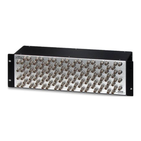
Page 10: Figure 2-1: Front Panel Of Srf3-64-1X2 Chassis
SRF Series Splitters and Combiners Figure 2-1: Front Panel of SRF3-64-1x2 Chassis Figure 2-2: Rear Panel of SRF3-64-1x2 Chassis Page-6 Revision 0.3... -
Page 11: Figure 2-3: Front Panel Of Srf3-32-1X4 Chassis
SRF Series Splitters and Combiners Figure 2-3: Front Panel of SRF3-32-1x4 Chassis Figure 2-4: Rear Panel of SRF3-32-1x4 Chassis Page-7 Revision 0.3... -
Page 12: Figure 2-5: Front Panel Of Srf3-16-1X8 Chassis
SRF Series Splitters and Combiners Figure 2-5: Front Panel of SRF3-16-1x8 Chassis Figure 2-6: Rear Panel of SRF3-16-1x8 Chassis Page-8 Revision 0.3... -
Page 13: Figure 2-7: Front Panel Of Srf3-8-1X16 Chassis
SRF Series Splitters and Combiners Figure 2-7: Front Panel of SRF3-8-1x16 Chassis Figure 2-8: Rear Panel of SRF3-8-1x16 Chassis SRF1 models occupy 1RU of rack space and have similar layouts but with fewer connectors than the depicted SRF3 models. -
Page 14: Specifications
SRF Series Splitters and Combiners SPECIFICATIONS 3.1. SRF1 SRF1 SRF1-16-1x2 SRF1-8-1x4 SRF1-4-1x8 SRF1-2-1x16 Number of 16 1x2’s 8 1x4’s 4 1x8’s 2 1x16’s Channels Frequency 40MHz-300MHz 40MHz-300MHz 600MHz-2200MHz 800MHz-2200MHz Range Insertion Loss 4.2dB±0.5dB 7.5dB ± 0.75dB 11dB ± 1dB 14dB ± 1dB Isolation >60dB...
Need help?
Do you have a question about the SRF Series and is the answer not in the manual?
Questions and answers