
Related Manuals for GPI GPI-122


Summary of Contents for GPI GPI-122
- Page 1 GPI-120/120L series Instruction Manual GPI-122 GPI-122L GPI-125 GPI-125L NO.3.20110322...
- Page 2 Preface Congratulations! We, GPI are proud to present you with these GPI-120 series instrument. Your total station is a robustious and reliable instrument whose performance and design are excellent. To fully appreciate and protect your investment, we suggest that you take the necessary time to read and fully understand this manual.
-
Page 3: Table Of Contents
1. Precautions for Safety ..................4 1.1 NOTE......................4 1.2 Definition of Indication ................5 1.3 Safety Standards for Laser ( GPI-120 series ) ........... 6 1.4 About User....................7 1.5 Exceptions from Responsibility..............8 2. Preparation before Measurement ..............9 2.1 About Battery..................... - Page 4 7.1 Distance Setout..................26 7.2 Coordinates Setout Measurement ............28 8. Area ........................ 30 8.1 Area Calculation by Measured Data or Input Data ......... 30 9. Offset Measurement ..................32 9.1 Distance Offset Measurement..............32 9.2 Angle Offset Measurement ..............33 9.3 Plane Offset Measurement................
-
Page 5: Precautions For Safety
When the instrument working, it is normal if you hear the noise from instrument motor, it will not affect the instrument work. Stored data responsibility GPI-120 should not be held liable for the lost data because of wrong operation. -
Page 6: Definition Of Indication
Do not put the battery in the fire or high temperature condition. Explosion, damage could result. Do not use the battery which is not specified by GPI-120. Fire, electric shock or burn could result. Do not use the power cable which is not specified by GPI-120. Fire could result. -
Page 7: Safety Standards For Laser ( Gpi-120 Series )
Do not drop the instrument or tripod, series damage could result. Before use it, check the central screw is tight. 1.3 Safety Standards for Laser ( GPI-120 Series ) GP-120 series adopt the class of Laser Product according to IEC Standard Publication 60825-1 Amd. -
Page 8: About User
Laser emit Note for Safety WARNING ● Never point the laser beam at other's eyes, it could cause serious injury. ● Never look directly into the laser beam source, it could cause permanent eye damage. ● Never stare at the laser beam, it could cause permanent eye damage. ●... -
Page 9: Exceptions From Responsibility
1.5 Exceptions from Responsibility 1. The user of this products is expected to follow all operating instructions and make periodic checks of the product’s performance. 2. The manufacturer, assumes no responsibility for results of a faulty or intentional usage or misuse including any direct, indirect, consequential damage, and loss of profits. -
Page 10: Preparation Before Measurement
2. Preparation before Measurement 2.1 About Battery 2.1.1 Battery Power Symbol 92°18' 22" 187°07' 15" Save Set0 SetA P1/2 Measurement is possible The battery is lower, it is better to replace or recharge it Measurement is impossible, it is necessary to replace or recharge NOTE: ... -
Page 11: Replace The Battery
◆ It is suggested to check every battery power before field work. 2.1.2 Replace the Battery 1. Remove the battery ①Press the button downward as shown left ②Remove the battery by pulling it toward you 2.1.3 Recharge the Battery 2. Mount the battery ①Insert the battery to the instrument ②Press the top of the battery until you hear a Click. -
Page 12: Setting Up The Instrument
NOTE: The indicator light on the charger will illuminate three separate colors for varies mode conditions: Solid Red Light — indicates that the charger is working; Solid Green Light — indicates that the charge has finished; Flashing Red Light — indicates no battery on charging, poor connection or some problems exist. - Page 13 3. Move the tripod legs to centre the circular level. The instrument is now roughly leveled-up. 4. Center the bubble in the circular level] Screw A Screw B Loosen the horizontal motion clamp, and turn the instrument till the plate level is perpendicular to a Plate level line shaped with screws A and B.
-
Page 14: Basic Functions
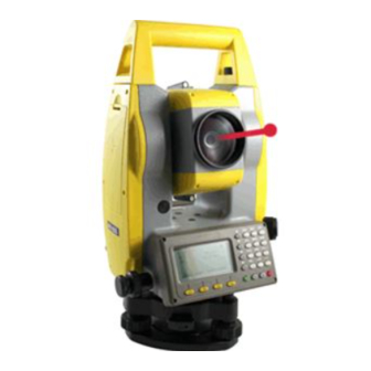
3. Basic Functions 3.1 Nomenclature Handle Optical sight Objective Vertical Plate level tangent screw Screen Keypad RS-232C port Tribrach fastening screw Tribrach... - Page 15 Handle screw Battery Indtrument height mark Eyepiece Focusing Optical knob Plummet Horizontal tangent screw Circular level Leveling screw Tribrach...
-
Page 16: Basic Key Operation
3.2 Basic Key Operation NOTE: 1. ”Power” indicate 2. Basic measurement is composed of angle and dist and coordinate measurement mode Keys Description Keys Description Select the functions matching 1. Enter into angle measurement .F1 ~ F4 the softkeys mode (under basic measurement mode) 1. -
Page 17: Mode Diagram
3.4 Mode Diagram 廴 Angle mode / basic measurement mode 92°18' 22" –Collection– 187°07' 15" 1.Select file ▲ 2.Setup station 3.Setup BSS Save Set0 SetA P1/2 4.Sequence of collection 5.Collection [DIST] ▼ [ANG] –Setout– 1.Setup station ▲ Dist mode/basic measurement 2.Setup BSS 3.Setout 4.Odd coordinate... -
Page 18: Power On/Off
3.5 Power On/Off I. Power on 1. Confirm the instrument is leveling, press the Type : GPI-122L S/N : A00001 red key 【POWER】. Ver : OCT 10 2010 2. Release 【POWER】,the instrument will 92°18' 22" display the angle mode screen. -
Page 19: How To Configure
next alphabet ‘U’ is relational with【7】.click Setup station 【7】,’SS’ will present in inputbox, click【7】 Pt.name SUN . again ‘ST’ will present in inputbox, click【7】 again, ’SU’ will present in input box. 4. Click【5】, ’SUN’ will present in input box. B.S. Clear Num. - Page 20 6. Factor Press【F4】, pop up “atmosphere parameter setting” dialog box, after you input temperature and atmospheric pressure, the PPM value will be calculated automatically. when you press【F3】the EDM will return current EDM signal.【ESC】 will quit signal show; Another setting and config is operated by main menu — “parameter” able 3-1 List of measurement condition setting Item Options...
-
Page 21: Angle Measurement
4. Angle Measurement 4.1 Measure a Horizontal Angle of Two Points 1. Sight the 1 target. 92°18' 22" Press F2:【SET0】to set the 1 target as 0°at P1 in 0°00' 00" the measure mode. Save Set0 SetA P1/2 2. Sight the 2 target. -
Page 22: Distance Measurement
5. Distance Measurement Please set the following items before distance measurement: Prism constant K option PPM Select reflector Grid scale G EDM mode setting by the application 【Procedure of distance measurement】 1.Aim at the target. Press F2: 【 MEAS】 at P1 in the 92°18' 22"... -
Page 23: Coordinate Measurement
6. Coordinate Measurement It is possible to find the 3D coordinates of a target by coordinate measurement. Please input the Station coordinate, instrument height, target height, backsight. Coordinate(or azimuth angle)and azimuth before coordinate measurement. Target Ht Inst. Ht Target point Occiped point 6.1 Input the Occupied Point Data 【Procedure of inputting occupied point data】... - Page 24 F4:【Read】to browse the coordinate file and find Set station out the point that you need. Press F3: 【Info】 you can >BSS: Code see all the information of the station if you have got T.H.: 1.800 the point. * file list Input Pop Info Read...
-
Page 25: Azimuth Setting
▲ ▼ ◆ Press keys { } / { } to move one by one. ◄ ► ◆ Press keys { } / { } to turn the previous/next page. ◆【Begin】: Press it and the first point on the first page will display. ◆【End】: Press it and the last point on the last page will display. - Page 26 Where: N0-E0-Z0: occupied point coordinates S:SD Z:Zenith angle Az:Azimuth angle IH:Instrument height TH:Target height Target height Zenith angle Target (N-E-Z) N0-E0-Z Azimuth angle 【Procedure of 3D coordinates measurement】 1. Aim at the target point. 92°18' 22" 2. Select F2:【Meas】to start. The coordinate value 0°00' 18"...
-
Page 27: Setout Measurement
7. Setout Measurement Setout measurement is used to Setout the required point. The difference between the previously inputted data to the instrument(the Setout data)and the measured value can be displayed by measuring the horizontal angle, distance or coordinates of the sighted point. - Page 28 【Procedure of distance Setout measurement】 1.Press F2: 【 Setout 】 at P2 in the distance 92°18' 22" measurement mode. 187°07' 15" Offset Setout m/f/I P2/2 Setout(dist) 2.Select one of the distance setout modes (HD,SD,VD) by pressing F3:【Mode】 Press【ENT】to accept the selection B.S.
-
Page 29: Coordinates Setout Measurement
7.2 Coordinates Setout Measurement After setting coordinates for the point to be Setout, the instrument calculates the Setout HA and HD. By selecting the HA and then the HD Setout functions, the required coordinate location can be Setout. To get the Z coordinate, attach the target to a pole etc, with the same target height. Distance Back sight station... - Page 30 4. If you can remember the point then you input the pointname,else you can press directly【ENT】. Pt.name B.S. Alph. Clear 5.The point list will appear.you search the point Pt.(B.coo)1/19 that you need in the list,if you find the you press F4: 1A: 100.000 120.000 A001: 100.000 100.000 【...
-
Page 31: Area
8. Area Calculate an area shaped with several points. The coordinate data of the points could be either measured or input by hand. Input: Output: Coordinates: P1 (N1, E1) Area:S P2 (N2, E2) P3 (N3, E3) NOTE: The number of points: 3 ~ 20. ◆... - Page 32 3. Input a point coordinate or you can press F3: Point(Area) 【Pop】to call an existing coordinate. B.S. Clear Enter 4. After inputing the coordinate. the coordinate Survey(Area) always is inserted behind the last select bar, and Pt01: 100.000 120.000 Pt02: 100.000 100.000 current coordinate turn into a selected bar.
-
Page 33: Offset Measurement
9. Offset Measurement Offset measurement are performed in order to find a point where a target cannot be installed directly or to find the distance and angle to a point which cannot be sighted. It is possible to find the distance and angle to a point you wish to measure(target Point) by installing the target at a location(offset point)a little distance from the target point and measuring the distance and angle from the surveying point to the offset point. -
Page 34: Angle Offset Measurement
2. Aim at the prism to start EDM, if you need the Offset (dist)–Prism 356°50' 27" coordinate of A0 you should set the height of prism to zero. if you need the coordinate of A1 you should set the height of prism to the real height. Meas T.H. -
Page 35: Plane Offset Measurement
【Procedure of angle offset measurement】 1.Select the function of 【angle offset Measurement】 –Offset– 1.Angle offset ▲ 2.Dist offset 3.Plane offset 4.Column offset 2. Start EDM , if you need the coordinate of A0 Offset (angle)–Prism you should set the height of prism to zero. if you 356°50’27”... - Page 36 P1 [prism] [prism] P2 [prism] P1,P2,P3 are the points where distance can obtain, the height should be setting to O.PO is the point that need measuring. station 【Procedure of Plane offset measurement】 Offset (Plane)–pt.1 1. Press F1:【Meas】,start EDM to obtain the 1°55' 42"...
-
Page 37: Column Offset Measurement
9.4 Column Offset Measurement Sometimes we wish to obtain the coordinate of column center where we cannot find. Fortunately, we can measure the distances of another points on the column, in this time the plane offset measurement can be used. the figure is shown as follow: 【Procedure of Column offset measurement】... -
Page 38: Mlm
10. MLM MLM is used to directly measure slope distance, horizontal distance and the height difference from one base point to other points without moving the instrument. MLM have two mode, one is MLM (A-B,A-C) , the other is MLM (A-B,B-C) ,the two modes are shown as follow. - Page 39 【Procedure of MLM measurement】 –Grid coefficient– 1. If considering the effect of grid scale you should 1.with grid scale ▲ select menu item 1,else you should select menu 2.without grid scale item 2; –MLM– 1.MLM(A-B,A-C) 2. Select one of two modes ▲...
-
Page 40: Height Measurement (Rem)
11. Height measurement (REM) REM is a function used to measure the coordinate and height to a point where a target cannot be directly installed such as power lines, overhead cables or bridges, etc. Target point B α2 α1 B’ Here is the equation used to calculate the data presented in above figure: Ht=H1+ S*cosα1*tgα2-S*sinα1 H2= S*cosα1*tgα2-S*sinα1... - Page 41 4. Then VD(difference of height)appear, first Height-Gnd to target display the height of prism. 88°18' 22" 1°46' 31" 1.000m T.H. HDist 5.If you rotate the telescope then VD will change, Height-Gnd to target 88°06' 28" when you aim at the target the VD is the difference 1°46' 31"...
-
Page 42: Intersection
12. Intersection Intersection program is used to determine the coordinates of an instrument station (unknown) by measuring several known points. Coordinate data in memory could be read. Input Coordinates of known points: Xi, Yi, Zi Measured HA: Hi Measured VA: Vi Measured distance: Di Output Coordinate of occupied data: Xo, Yo, Zo... -
Page 43: Coordinates Intersection
12.1 Coordinates Intersection 【Procedure of Intersection】 Intersection-P1 1. Input a known point. you can press F1:【Input】 >Pt.name: to input the point coordinate by coordinate, or you Code can press F2:【Pop】to call an existing coordinates T.H.: 1.000 * file list for current coordinates file. Input Info Read... -
Page 44: Elevation Intersection - Coor.z
6. Press F4:【dCoor】the coordinate of instrument Intersection-result station will be shown. you can Press F1:【Set ST】 -0.004 to setup station and press F2:【Set A】to setup the 0.003 0.003 Azimuth of the instrument. Set ST SetA Coor Intersection-result 7. Setup station. -0.004 0.003 0.003... - Page 45 2. Press F1:【MEAS】starting EDM and obtaining Coor.Z-No.1 1°46' 36" the slope distance. Meas Mode Enter 3. Finished measuring, you can press F4:【Enter】 Coor.Z-No.1 to accept the data. 1°46' 36" 4.897m 4.837 0.767 Meas Mode Enter Coor.Z-No.1 4. One or more known point can calculate the 1°46' 36"...
-
Page 46: Precautions When Performing Intersection
12.3 Precautions When Performing Intersection In some cases it is impossible to calculate the coordinates of occupied point if the unknown point and three or more known points are arranged on the edge of a single circle. It is also impossible to calculate if the included angle between the known points is too small. -
Page 47: Point Projection
13. Point Projection Point projection is used for projecting a point to an established baseline. By measuring a point, its offset to start point, the horizontal distance and vertical distance between the point and baseline can be calculated. the figure is shown as follow. Pt’... - Page 48 3. Aim at and measure the end point of the baseline. Pt.project(end) 83°09' 38" then defining baseline is over. 24°30' 08" 6.408m 6.362 Meas T.H. Mode Enter 【Procedure of point projection】 Survey(Pt.project) 15°23' 50" -0.903m -0.867 -0.099 Meas T.H. Mode Survey(Pt.project) 15°23' 50"...
-
Page 49: Inverse
14. Inverse The distance and azimuth from a start point to an end point could be calculated according to input their coordinates. Input: Output: Coordiante of start point: N0,E0,Z0 Distance: D Coordinate of end point : N1,E1,Z1 Azimuth: Az End point Start point This function can be implented in MLM when all coordinates is called from the coordinates file. -
Page 50: Roadway
15. Roadway Roadway application program is composed of designing and roadway setout. when you select roadway function then the menu is appeared as follow: –Roadway– 1.Open Raod file ▲ 2.New H curve file 3.New V curve file 4.Resume H curve 5.Resume V curve 6.Road Setout ▼... -
Page 51: Define The Horizontal Curve Of Roadway
Exit point PTI Entrance point PTO Attribute of point of intersection 15.1 Define the Horizontal Curve of Roadway 【Procedure of defining Horizontal Element】 1. Select the mathod of element to define horizontal roadway. press F1:【Line】first. Curve define(H) Mileage: 0.000 Azimuth: 0°00' 00"... - Page 52 3. Input the start azimuth and the length of line Define(H)_Line Azimuth: Length: Clear Enter 4. Calculate the mileage and azimuth of the fan-out Define(H)_02 point Mileage: 150.000 Azimuth: 5°00' 00" Line Circle Spial 5. For example, input a circle whose radius is 100 Define(H) _Circle and length is 20;...
- Page 53 9. Max number of element is 20.press 【 ENT】 to pop List(H element) up the list box of all inputed element. Press F1: 01Begin: 02Line: 【Save】to save all element to current 03Circle: H-LINE-TYPE file and quit defining. Press F2: 04Spiral: 【View】to browse the detailed information of a Save View...
-
Page 54: Defining The Vertical Curve Of Roadway
15.2 Defining the Vertical Curve of Roadway The speciality of the roadway slope should be described by the vertial curve, there are three attributes on the vertical curve—mileage, altitude and length, the mileage is representative of the point where the slope is changed, the altitude is the altitude of the point where the slope is changed ,the length indicate how much curve length is disigned to implement the slope changing. - Page 55 3. The azimuth must be setup, you can use menu item 3. –Road setout– 1.Select file ▲ 2.Setup ST 2.Setup BSS 4.Road Setout The figure for road setout is shown as follow center left dH(-) right dH(-) left distance right distance Space between stake center...
- Page 56 2. Input left distance,right distance etc. Roadsetoutpara 1/2 Leftdist: Rightdist: Left dH: Right dH: B.S. Clear Enter ▲ ▼ 3. Use【 】to set the mile on the stake that RoadsetoutRightEdge 】 【 Mile: 100.00 ◄ ► you need to setout , uset【 】to select 】【...
-
Page 57: Fileman
16. Fileman The instrument use a FAT16 file system to manage the data, all data obtained form measuring can save to current measurement file. the extension name of measurement file is *.MEA. all coordinates used by measurement can be picked up from current coordinate file, the extentsion name of current coordinate file is *.COO.sometimes you need to note an attribute of a point when you measure, the code file maybe a good helper, the extension name of code file is *.COD. - Page 58 the end record.F2:【PgUp】to show the previous record.F3:【PgDn】to show the next record.【 ★ Baud: 115200 】 Filename: A.COO to edit the record if ‘*’is on the interface. only No.: 21 point name ,code and height can be edited. Fast Slow File Import 5.
-
Page 59: Prompt,Warning And Error Messages
17. Prompt,Warning and Error Messages “ Tilt Over ” – The tilt compensater is out of range “ Points NO.<=20 ” – The number of points should be less than 20 “ Cannot find ” – Cannot find any point by the name “... - Page 60 “ 90° Beep on ” — Switch on Beep on rectangle position “ Setup station first ” — Please setup station before seting BSS “ Open error ” — Cannot open file “ T.H. overtop ” — The height of the prism is out of range “...
- Page 61 Giant Giant Precision Instrument Co., Ltd. International sales dep. No.69, Anhe Rd., Zhonghe Dist., New Taipei City, Taiwan (R.O.C.) Zip:23576 Tel: 886-2-2231-7282 Fax: 886-2-2231-7281...
Need help?
Do you have a question about the GPI-122 and is the answer not in the manual?
Questions and answers