Table of Contents
Advertisement
Quick Links
Advertisement
Table of Contents

Related Manuals for GPI GPI-ZL21R


Summary of Contents for GPI GPI-ZL21R
-
Page 1: Laser Plummet
GPI-ZL21R Laser Plummet INSTRUCTION MANUAL... - Page 2 Thanks for your trust on our product! GPI-ZL21R laser plummet is precision surveying instrument. In order to get maximum use of the features of you new product we recommend that you read the manual in details. The laser class of GPI-ZL21R is 2, please don't stare into beam.
-
Page 3: Table Of Contents
Content 1. Applications and functions…………………………………………………….3 Main specifications……………………………………………………………4 3. Nomenclature of parts…………………………………………………………6 4. Operation………………………………………………………………………8 4.1 Setting, leveling and centering..............8 4.2 Aim......................11 4.3 Upward…………………………………………………………………...12 4.4 Measuring vertical outline………………………………………………..13 4.4.1 Optical measurement……………………………………………...13 4.4.2 Laser measurement………………………………………………..15 4.5 Transfer on vertical direction…………………………………………….14 5. Battery………………………………………………………………………..16 - 2 -... -
Page 4: Applications And Functions
1. Applications and functions Straight direction and centralized energy are laser's characters, GPI-ZL21R, add two laser diode bases on optical plummet, one laser beam through telescope. The other laser beam are directed down through the plummet, it is easy to locate a given reference point. -
Page 5: Main Specifications
2. Specifications ±2.5mm / 100M Accuracy (Upward laser) ±1mm / 1.5M Accuracy (Downward laser) Plate level sensitivity 20" / 2mm Image Erect Magnification 25 X Telescope Field of view 1° 50' Objective lens 36mm Focus 0.8m Laser Wave length 635nm (upward) Laser class 2(IEC60825-1:2001-11)... - Page 6 ≦3mm / 50M Beam spot diameter Error between telescope sight ≦5" axis and vertical axis Upward Error between laser axis and ≦5" sight axis Wave length 635nm Laser class 2(IEC 60825-1 :2001-11) Laser Working distance 0.5~80m Plummet Output power < lmw, Adjustable ±...
-
Page 7: Nomenclature Of Parts
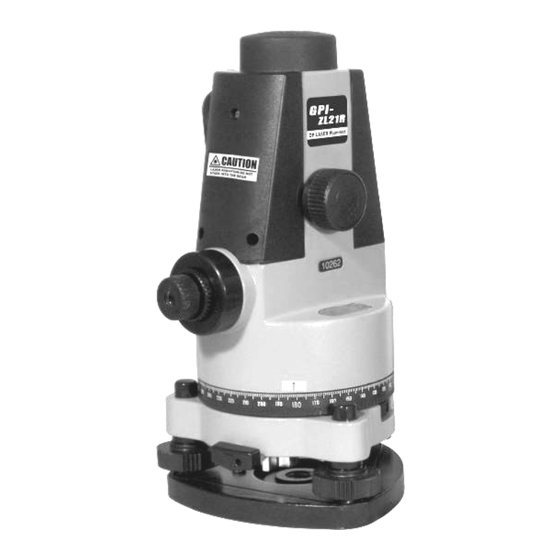
3. Nomenclature of parts Laser label Telescope focusing knob Eyepiece Eyepiece cover Circular level Fig. 1 - 6 -... - Page 8 Objective cover Handle Battery pack cover Laser cover Plate level Horizontal circle Leveling screw Fig. 2 - 7 -...
-
Page 9: Operation
4. Operation 4.1 Setting, leveling and centering Setting up the tripod on the measure-station point and put the instrument on tripod head, then attach it to the tribrach by the center screw. Adjust the height of tripod to make eyepiece on same level with sight line. Adjust tripod to make bubble centering. - Page 10 Leveling Screw A Screw B (1) Leveling with the circular level By adjust leveling screws A and B, position the bubble in the center of vial (Fig.4). Fig. 4 Adjust the leveling screw C, position the bubble in the center of circle(Fig.5). Screw C Screw A Screw B...
- Page 11 (2) Leveling precisely with plate level Screw A Screw B Loosen horizontal clamp screw, place the plate level in parallel with a line joining Plate level leveling screws A and B. Adjust the Bubble leveling screw, position the bubble in the center of plate level(Fig.6).
-
Page 12: Aim
Centering (1) Switch on the laser switch, adjust the plummet focusing knob to move the laser spot on the same horizontal plane with ground mark point. (2) Loosen the tribrach clamp knob and move the instrument until the center mark coincides with the ground mark point. (3) Repeat leveling and (2) steps. -
Page 13: Upward
target as observer moves slightly. Otherwise, repeat the above steps until there is no parallax. 4.3 Upward (1) Optical plummet Leveling the instrument, make the index points to zero graduation first, then read out the first point. Then rotate the instrument through 180 and read out the second point, take the average of these two points as final result. -
Page 14: Measuring Vertical Outline
4.4 Measuring vertical outline Fig. 9 Place a tripod around the object, and set up the instrument on it, adjust the leveling screws until the bubble always in the center of place level when rotating instrument to any direction. 4.4.1 Optical measurement (1) Turn the eyepiece until the reticle cross-hairs is clear. -
Page 15: Laser Measurement
(3) Move the laser target at regular intervals on vertical direction, and repeat the (2) procedure. The vertical outline of object can be measured. 4.4.2 Laser measurement (1) Turn the eyepiece until the reticle cross-hairs is clear. (2) Place a laser target close to object, adjust the focusing knob until the laser spot on laser target is the smallest, reading out the value. - Page 16 transfer points. (1) Set up the instrument in the mine and tum Fig. 10 on the upward laser, move the instrument until the laser collimating the point C. (2) Turn on the downward laser, the laser spot on the mine ground point E is related to point (3) Repeat (1) to collimate the point D and get the point F as step (2).
-
Page 17: Battery
5. Battery The power is 2pcs AA batteries or rechargeable battery. Replace the batteries: The working time of 2pcs AA batteries is about 10 Hours. Please replace the batteries when the laser light becoming dark. The operating procedure is as follows: Push the fixing button on battery pack towards right and open the pack cover, take out the old batteries and install the new ones according to the indicating of positive and negative mark. - Page 18 Giant Precision Instrument Co., Ltd. International sales dep. No.69, Anhe Rd., Zhonghe Dist., New Taipei City, Taiwan (R.O.C.) Zip:23576 Tel: 886-2-2231-7282 Fax: 886-2-2231-7281...
Need help?
Do you have a question about the GPI-ZL21R and is the answer not in the manual?
Questions and answers