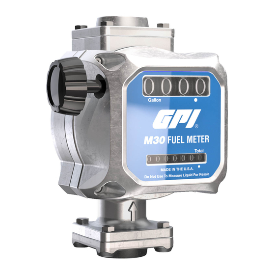
GPI M30-G6N Product Owners Manual
5-30 gpm 19-114 l/min fuel meter
Hide thumbs
Also See for M30-G6N:
- Troubleshooting manual (17 pages) ,
- Product owners manual (32 pages)

Related Manuals for GPI M30-G6N


Summary of Contents for GPI M30-G6N
- Page 1 Product Owner’s Manual 5-30 GPM (19-114 L/min) Fuel Meter Models: M30-G6N, M30-L6N, M30-G8N, M30-L8N, M30-G8B, M30-L8B 04/2020 921529-01 Rev C...
- Page 2 Thank you for choosing a Great Plains Industries product, and congratulations on your purchase! Headquartered in the heartland of the U.S., GPI strives for integrity, innovation, continuous improvement, and dependability—values you will immediately recognize when using our products. The maintenance policies and procedures outlined in this manual emphasize our commitment to safety and our dedication to you as a customer.
-
Page 3: Before You Begin
BEFORE YOU BEGIN Usage Requirements • This manual covers fuel meter models M30-G6N, M30-L6N, M30-G8N, M30-L8N, M30-G8B, and M30-G8B. • This fuel meter is designed, tested and approved for use with thin viscosity petroleum fuels such as gasoline blends (up to E15), diesel fuel blends (up to B20) and kerosene. -
Page 4: General Safety Instructions
This product shall not be used for pumping fuel or other liquids into aircraft. SPECIFICATIONS M30-G6N, M30-L6N, M30-G8N, M30-L8N, M30-G8B, & M30-L8Bf Dimensions A. Meter Assy Width 5.91 in. (15.01 cm) B. Meter Assy Height 7.88 in. - Page 5 SPECIFICATIONS ( CONTINUED ) M30-G6N, M30-G8N, & M30- M30-L6N, M30-L8N, & G8B (GALLON MODEL) M30-L8B (LITRE MODEL) Unit of Measure U.S. Gallon Litre Flow Range 5 to 30 GPM 19 to 114 L/min Operating Temperature -20° F to 125° F -29°...
-
Page 6: Declaration Of Conformity
DECLARATION OF CONFORMITY We declare, that the product: Product Name: M30 Mechanical Fuel Meter Model Numbers: M30-G*N, M30-L*N, M30-G*B, M30-L*B Conforms with the requirements of the Directive (s) below by compliance with the Standards subsequently listed: 1. Council Directive 2014/34/EU relating to equipment and protective systems intended for use in potentially explosive atmospheres, ISO 80079-36: 2016, Non-electrical equipment for explosive atmospheres- Basic methods and requirements. -
Page 7: Installation Instructions
INSTALLATION INSTRUCTIONS Your system must be installed on a vented tank. If the tank is unvented, your local dealer or distributor can supply a pressure cap. If the meter is located in a rigid piping system where the fluid is trapped (for example, by gravity, valves or nozzles) thermal expansion of the fluid can create pressure spikes that can damage a meter. - Page 8 INSTALLATION INSTRUCTIONS ( CONTINUED ) Change Register Orientation NOTE: If the meter is plumbed in any orientation other than bottom-up flow, the register may need to be reoriented. Using a 3mm L-hex wrench, remove the (4) screws that hold register in place Rotate the register to the desired orientation, making sure the O-ring is fully seated (see Figure 3).
- Page 9 INSTALLATION INSTRUCTIONS ( CONTINUED ) Installation Meter - Threaded Connection Remove protective plugs from the meter inlet and outlet ports. Wrap threaded male connections with thread tape or use a pipe sealant compound compatible with petroleum fuels. Install the meter using appropriately sized fittings. “INLET” and “OUTLET”...
- Page 10 OPERATION ( CONTINUED ) Always follow safety precautions when operating this equipment. Review the General Safety Instructions at front of manual. IMPORTANT: Before each use, visually check the meter to ensure it is securely connected to other system components and there is no leakage. Promptly wipe spilled fuel from the meter’s exterior and other system components.
-
Page 11: Troubleshooting
TROUBLESHOOTING Symptom Possible Cause(s) Corrective Action A. Meter counter 1. Dirty register 1. Clean register does not operate (Normal fuel delivery) 2. Broken register 2. Replace register 3. Foreign mateial in register 3. Remove and clean register or nutator assembly or nutator assembly B. -
Page 12: Maintenance
MAINTENANCE NOTE: This meter is designed for minimum maintenance. Inspect meter and components regularly for fuel leaks. Keep the meter exterior clean to help identify leaks. IMPORTANT: This fuel meter is designed, tested and approved for use with thin viscosity petroleum fuels such as gasoline blends (up to E15), diesel fuel blends (up to B20) and kerosene (see BEFORE YOU BEGIN: Usage Requirements at front of manual). - Page 13 REPAIR IMPORTANT: Carefully inspect all parts for wear or damage. Replace components, as necessary. The Illustrated Parts List gives information on replacement parts and kits. Review the Safety Instructions before proceeding. Avoid prolonged skin contact with petroleum fuels. Use protective goggles, gloves and aprons in case of splashing or spills.
-
Page 14: Parts And Service
PARTS & SERVICE For warranty consideration, parts, or other service information, please contact your local distributor. If you need further assistance, contact the GPI Customer Service Department in Wichita, Kansas, during normal business hours. A toll free number is provided for your convenience. - Page 15 IMPORTANT: Please contact GPI before returning any parts. It may be possible to diagnose the trouble and identify needed parts in a telephone call. GPI can also inform you of any special requirements you will need to follow for shipping fuel dispensing equipment.
- Page 16 B. the product has been subjected to neglect, misuse, abuse or damage or has been installed or operated other than in accordance with the manufacturer’s operating instructions. To make a claim against this warranty, contact the GPI Customer Service Department at 316-686-7361 or 800-835-0113. Or by mail at: Great Plains Industries, Inc.
Need help?
Do you have a question about the M30-G6N and is the answer not in the manual?
Questions and answers