Table of Contents
Advertisement
Quick Links
Advertisement
Table of Contents

Summary of Contents for GPI GM Series
-
Page 2: General Information
• Disconnect external power to the transmitter before litres. detaching or attaching input or output wires. • The 4-20 mA Out with Display can be used on all GPI • Ground loops between sensor and user equipment can models, including the Precision G series, the Industrial damage the transmitter and can be dangerous. -
Page 3: Cable Guidelines
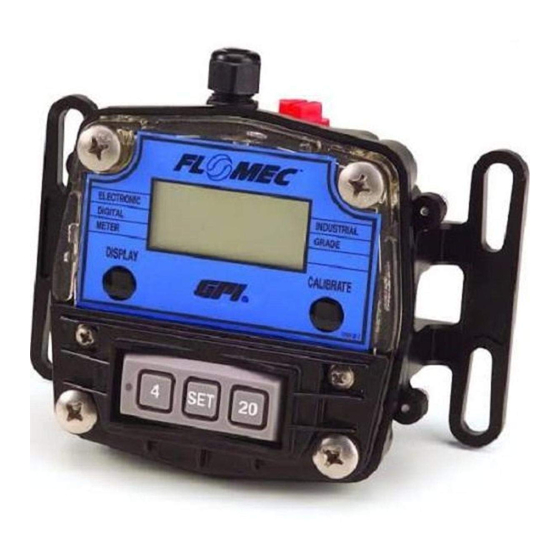
This manual refers to various models of GPI flowmeters. Determine what type of input the electronics will receive and Mount the GPI 4-20 mA Out with Display using bolts, screws what type of output, if any, you require. Use the diagrams or standard U-bolts for pipes. - Page 4 Customer Equipment With Built-in Power Supply – High Temp Applications Input: Standard Remote Sensor (Variable Reluctance Pickup Coil) Output: Customer Equipment, 0-20 mA Sensing, Built-in Loop Power Supply INPUTS OUTPUTS Loop (+) GPI Meter 4-20 mA Out (current) with Display Unpowered Coil-A...
- Page 5 W I R I N G D I A G R A M 3 — 4-20 mA or 0-20 mA Output — Customer Equipment Without Built-in Power Supply Input: Turbine Mounted Display or Conditioned Signal Sensor (See inputs from Diagram 1) Standard Remote Sensor (See inputs from Diagram 2) Output: Customer Equipment, 0-20 mA Sensing, Separate Power Supply Loop Power Supply INPUTS...
- Page 6 W I R I N G D I A G R A M 5 — Pulse Output — Customer Equipment Without Built-in Power Supply Input: Turbine Mounted Display or Conditioned Signal Sensor (See inputs from Diagram 1) Standard Remote Sensor (See inputs from Diagram 2) Output: Customer Equipment, Frequency Sensing, Separate Loop Power Supply Loop Power Supply INPUTS...
- Page 7 W I R I N G D I A G R A M 7 — 4-20 mA or 0-20 mA Output — Customer Equipment With Built-in Power Supply Input: Hall Effect* Output: Customer Equipment, 0-20 mA Sensing, Built-in Loop Power Supply HE Power Supply 4.5 - 24 VDC INPUTS...
- Page 8 W I R I N G D I A G R A M 9 — 0-5 V Output — Customer Equipment Without Built-in Power Supply Input: Reed Switch (See inputs from Diagram 6) or Hall Effect* (See inputs from Diagram 7) Output: Customer Equipment, 0-5 V Sensing, Separate Loop Power Supply Loop Power Supply INPUTS...
-
Page 9: About Calibration
“0.00.” You can do this even while fluid is flowing, in which Access to the configuration settings require a specific pro- case counting will resume after you release the DISPLAY cedure and a pin code available through the GPI Web site at button. www.gpi.net or call GPI Customer Serivce at 888-996-3837. -
Page 10: Calibration Curves
A “single point” or flowrate derived from the field calibration are visible when calibration may be used on the GPI GM series, or any other the field calibration setting is selected. positive displacement meter, with excellent results. Any pulse... - Page 11 K-FACTOR CALIBRATION PROCEDURES Your Actions Notes 6. Once you release the buttons, The computer is waiting Your Actions Notes the display will show the blinking for you to enter a pulse message “Pr 01” (or Pr 02, Pr 03, rate. Pulse rates are 1.
- Page 12 DISPENSE / DISPLAY Your Actions Notes FIELD CALIBRATION PROCEDURES 6. Once the flow has stopped, briefly When the display shows press and release both buttons. “0000.00” the computer At this point the computer display has stopped “watching” Your Actions Notes will change to “0000.00”...
-
Page 13: Lockout Feature
Setting the High (20 mA) Endpoint Your Actions Notes 1. Start the fluid pumping system. Set it for steady flow at 11. If you HAVE NOT dispensed any After you release the the highest anticipated rate (or the rate at which you want fluid, you can exit calibration with- buttons, the computer will a “maximum”... -
Page 14: Maintenance
The GPI 4-20 mA Out with Display offers a choice of five re- Optional 0-20 mA Mode sponse-time settings, selectable by the unit’s pushbuttons. A few current loop systems use 0-20 mA output. The input signal frequency of “0” produces an output analog signal of Procedure “0”... -
Page 15: Troubleshooting
TROUBLESHOOTING SYMPTOM PROBABLE CAUSE CORRECTIVE ACTION A. METER IS NOT 1. Field Calibration not performed properly. Field Calibrate again or select Factory Calibration. ACCURATE 2. Factory Calibration not suitable Perform a Field Calibration according to Calibration Section or for liquid being measured. select the proper Factory Calibration selection (i.e., gallon or litre). -
Page 16: Dimension Drawings
DIMENSION DRAWINGS... -
Page 17: Illustrated Parts Drawing
ILLUSTRATED PARTS DRAWING Item Item Part No. Description Req’d. Part No. Description Req’d. 120512-01 Switch Keypad Kit ............1 904002-44 Screw, 8-32 x 5/16 in............2 120048-01 Gasket ................1 125066-20 Cable, 20 ft...............1 12051803 Computer Kit (Hours) ............1 125066-3 Cable, 100 ft..............1 12051804 Computer Kit (Minutes) .............1 906005-47... - Page 18 SPECIFICATIONS – LOCAL MODEL Temperature: Ambient Temperature: +32°F to 140°F (0°C to 60°C) Applications: Cable: Use for indoor or outdoor applications where occasional No cable provided moisture is common. Mechanical Connections: Materials: Display is mounted directly to flow meter body. Acetal, Amorphous Nylon, Silicone Rubber, Polyester Electrical Connections: (decals), Viton (gasket &...
-
Page 19: Weee Directive
Coupled flowmeter may add additional error. telephone call. GPI can also inform you of any special require- Max. Conversion Resolution Uncertainty: (Loop current ments you will need to follow for shipping.


Need help?
Do you have a question about the GM Series and is the answer not in the manual?
Questions and answers