Table of Contents
Advertisement
Quick Links
Find Quality Products Online at:
SAVE THESE INSTRUCTIONS
TM Series Electronic Water Meters
User Manual
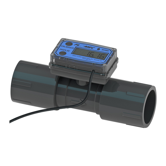
TM Meter with Computer Display
TABLE OF CONTENTS
English ...........................................................1
Español ..........................................................8
Deutsch .......................................................15
Italiano .........................................................22
Français .......................................................29
E N G L I S H
IMPORTANT NOTICE
Use TM Series meters with water and other
chemicals compatible with wetted compo-
nents. Do not use to meter fuel or incompatible
chemicals. TM Series meters are available with
either a computer for local electronic display, or
a conditioned signal output module to provide a
digital signal to customer interfacing equipment.
TM Series meters with computer display mea-
sure in gallons or litres. Refer to the Calibration
Section for details.
04/13
GlobalTestSupply
www.
TM Digital Pulse Meter
These meters are not legal for trade applications.
TM Series meters are very sensitive to electric
noise if operated within 1 to 2 inches of some
electric motors or other sources of electronic
noise.
Connections
Install your meter in-line either horizontally or
vertically or at the end of the hose adjacent to
the nozzle. Installation to metal connections is
not recommended. Install as follows:
1. Plan to install turbine with a minimum straight
pipe length as follows:
• Upstream from the turbine, allow a mini-
mum straight pipe length of 10 times the
internal diameter of the turbine.
• Downstream from the turbine, allow a
minimum straight pipe length of 5 times
the internal diameter of the turbine.
2. For Spigot (Pipe) End use only primer and
solvents approved for PVC gluing.
For NPT and BSP Fittings wrap all connec-
tions with 3 to 4 wraps of thread tape (optional
to use pipe thread sealant). Make sure the
tape does not intrude into the flow path.
Rev. B 920786-02
.com
sales@GlobalTestSupply.com
Advertisement
Table of Contents

Related Manuals for GPI TM050


Summary of Contents for GPI TM050
- Page 1 SAVE THESE INSTRUCTIONS TM Series Electronic Water Meters User Manual TM Meter with Computer Display TM Digital Pulse Meter These meters are not legal for trade applications. TABLE OF CONTENTS TM Series meters are very sensitive to electric English ............1 noise if operated within 1 to 2 inches of some electric motors or other sources of electronic Español ............8...
- Page 2 3. Attach meter with arrow pointed in the direc- WARNING tion of fluid flow. Always use appropriate thread sealant or 4. For NPT and BSP Fittings - Hand tighten flange gaskets when connecting product the meter at the housing ends. Do not use process piping.
- Page 3 Wiring Diagram 2 SQUARE WAVE OUTPUT 6 volt Square White Wave Signal Terminal Block Customer Interfacing Equipment Black Common (Ground) The terminal block is identified as follows: Pin #1 6 volt square wave Pin #2 +9 to 35 volt DC Input (not used) Pin #3 Common Ground Pin #4 Open Collector signal Output (not used) Conditioned Signal Output...
- Page 4 2. Meter an exact known volume into an ac- dim, faded or the low battery message appears curate container. For best results, meter with (see below), the batteries need to be replaced. one continuous full stream. Reference the Maintenance Section for details. 3.
- Page 5 TM Series Meters 4. All enabled units-of-measure remain visible and selectable – the entered correction will ½ inch meter 1 GPM (3.8 LPM) be applied to all enabled units. ¾ inch meter 2 GPM (7.5 LPM) 5. To return to factory calibration (FAC), press 1 inch meter 5 GPM (18.8 LPM) and hold both CALIBRATE and DISPLAY...
-
Page 6: Battery Replacement
212°F (100°C). Do not short circuit or install with Inlet and Outlet: incorrect polarity. DO NOT INCINERATE. Spigot (Pipe) End Models: TM050/TM050-P ½ inch Schd. 80, CAUTION Spigot (Pipe) TM075/TM075-P ¾ inch Schd. 80, Batteries should ONLY be replaced with... - Page 7 U.S. Measurement Operating Temperature: 0° to +60° C (Do not allow fluid to freeze inside meter.) Unit of Measure: Gallon Storage Temperature: –40° to +70° C Flow Range: Product Weight: ½ inch 1 - 10 GPM Spigot (Pipe) ¾ inch 2 - 20 GPM ½...
Need help?
Do you have a question about the TM050 and is the answer not in the manual?
Questions and answers