Table of Contents
Advertisement
Quick Links
SAVE THESE INSTRUCTIONS
Fixed
Portable
05/13
Fixed and Portable
Ultrasonic Flowmeter (UFM)
TABLE OF CONTENTS
Key Aspects of QStar UFM.......................................... 3
Approvals/CE............................................................... 3
Measuring Principle ..................................................... 3
QStar Fixed UFM and Components ............................ 4
QStar Portable UFM and Components........................ 8
Operating ................................................................... 10
Getting Started .......................................................... 10
Preparing for Measurement ....................................... 13
Measuring with UFM.................................................. 15
Setup Parameters...................................................... 15
Measuring Windows .................................................. 31
Calibration ................................................................. 44
System Settings......................................................... 44
Troubleshooting ......................................................... 46
Software Update ........................................................ 53
Fluid Properties ......................................................... 54
Specifications ............................................................ 56
Owner's Manual
920222-01
Advertisement
Table of Contents

Related Manuals for GPI QME10


Summary of Contents for GPI QME10
-
Page 1: Table Of Contents
SAVE THESE INSTRUCTIONS Fixed and Portable Ultrasonic Flowmeter (UFM) Owner’s Manual TABLE OF CONTENTS Key Aspects of QStar UFM.......... 3 Approvals/CE............... 3 Fixed Measuring Principle ............. 3 QStar Fixed UFM and Components ......4 QStar Portable UFM and Components......8 Operating .............. - Page 2 Other ultrasonic transducers for smaller or larger pipe DIN, alligator clips) dimensions, as well as clamp-on temperature sen- • Digital output cable for the relay/pulse output sors, are available on separate order. Contact GPI at (Mini DIN, alligator clips) www.GPImeters.net or toll-free (888) 996-3837. • USB cable •...
-
Page 3: Key Aspects Of Qstar Ufm
KEY ASPECTS OF QSTAR UFM: APPROVALS/CE • Fixed or Portable system for measuring liquids in filled QStar UFM is compliant with the following piping systems. European Directives and Standards • Uses the ultrasonic transit-time differential method. Test Specifications • Heat measurement is included as standard application. 55011 B (11/2007) Clamp-on Fixed and Portable temperature sensors... -
Page 4: Qstar Fixed Ufm And Components
The UFM employs precise, ultrasonic transit-time dif- − ferential method. This method involves installation of two ultrasonic transducers on the surface of the piping α ⋅ ⋅ and their interconnection with the electronic evaluation Calculation of flow velocity [m/s] system. The ultrasonic transducers operate in alternating mode as transmitter and receiver with cyclic exchange of −... - Page 5 FIXED UFM AND COMPONENTS (Continued) MOUNTING MATERIAL AND QMF-PT100 Temperature sensors ACCESSORIES The clamp-on temperature sensors collect tem- perature data in heating and cooling circuits. Signal cables This data is then used to calculate heating and cooling quantities. Signal cables are a part of the ultrasonic transducers and cannot be separated from transducers.
- Page 6 FIXED UFM AND COMPONENTS (Continued) CONNECTOR BOARD FIGURE 12: Connecting Terminals (DC) QMF- QMF- PT100 PT100 RS232/ 485 Relay OUT2 OUT1 DO1 DO2 Reset Power 1 RS232/RS485 Interface boards Hardware Reset Digital Interface boards RS232 or RS485 are Used to reset unit (for hang-ups). available as an option to provide digital com- Power Supply munication via ASCI strings.
- Page 7 FIXED UFM AND COMPONENTS (Continued) Terminal Diagram Use cables with 16-26 AWG wires. Wires should Terminals Designation be stripped about .5 in. to allow proper contact Connection of upstream transducer to terminals. Red wire to be connected to + Black wire to be connected to - Connection of downstream transducer Red wire to be connected to + Black wire to be connected to -...
-
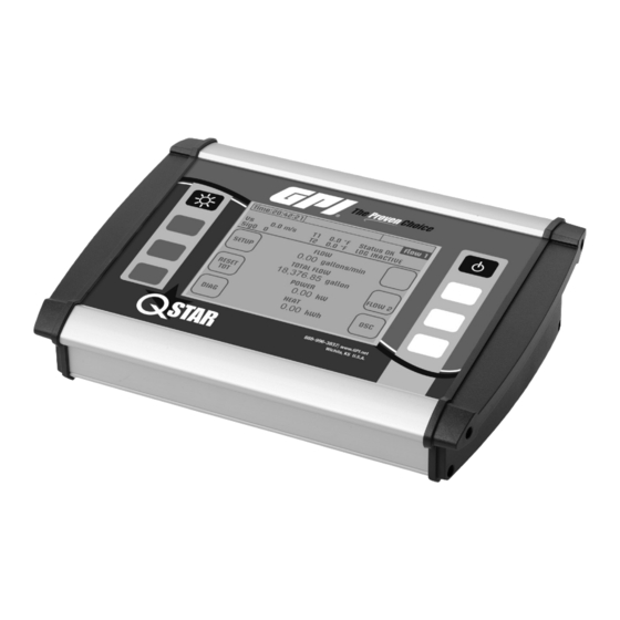
Page 8: Qstar Portable Ufm And Components
PORTABLE UFM AND COMPONENTS PORTABLE FLOW TRANSMITTER MOUNTING MATERIAL AND ACCESSORIES Your UFM consists of the ultrasonic transducers and the flow transmitter that are mounted onto your piping. Signal cables The flow transmitter processes the signals and provides the measurement results. FIGURE 16: PORTABLE Flow Transmitter (Top) and Mounted Ultrasonic Transducers (Bottom) Spacer bar for transducer mounting... - Page 9 PORTABLE UFM AND COMPONENTS (Continued) QMP-PT100 Temperature sensors FIGURE 21: Back view of Portable UFM connections (Optional) The clamp-on temperature sensors collect tem- perature data in heating and cooling circuits. Use this data to calculate heating and cooling quantities. FIGURE 20: QMP-PT100 clamp-on temperature sensors Power Reset Down...
-
Page 10: Operating
SAFETY INSTRUCTIONS HOW TO NAVIGATE • The flow transmitter cannot be operated outside the Use the corresponding multifunctional buttons: temperature range from -4° F to 140° F. Arrow buttons for • The ultrasonic transducers are sensitive to mechanical navigation stress such as impact and vibration. Always safeguard the transducers against strong vibration or impact to avoid damage or destruction. -
Page 11: Setting The Time And Date
2. Confirm the “SETUP LANG.” button 2. Select “COMPL Setup” when window appears. You are now in the main menu. Select all necessary 3. Use the arrows in the next window to select the dialog functions of the device in this menu. language. -
Page 12: Backup Battery
2. Select the “Time and Date” menu command 3. Enter the time as: Hour (hh): Minute (mm): Second (ss). Enter the date as: Month (mm): Day (dd): Year (yy). APPLIES TO PORTABLE QSTAR The status bar is located in the uppermost row of the display. Time Displays the current time (system time). -
Page 13: Preparing For Measurement
PREPARING FOR MEASUREMENT The following section elaborates on essential aspects that must be taken into account for successful flowrate measurements. STRAIGHT RUN REQUIREMENTS The selection of the mounting location has a significant impact on measurement quality. The charge and discharge areas listed in the following table should be taken into account. FIGURE 22: Straight run requirements... - Page 14 The drawing shows To measure pipes with unknown wall thicknesses the side view of the piping. a wall thickness gauge is avaiable from GPI. Ask GPI Customer Service Representative for more Mounting Ultrasonic Transducers On information or visit www.GPImeters.net.
-
Page 15: Measuring With Ufm
W-Mode SETUP PARAMETERS FIGURE 26: Mounting of Transducers in W-Mode Ths section defines the input of all data that is necessary for flow measurement. Transducer 1 Transducer 2 • “QUICK SETUP”: The Quick Setup guide offers step- by-step instructions on the essential tasks required to setup parameters. - Page 16 USING QUICK SETUP Accessing the setup dialog: After power on: Select “Setup” -> “Quick Setup” within the start sequence. In the primary measuring window “Flow 1”: Select “Setup” -> “Quick “Setup.” Enter the kinematic viscosity of the fluid: START Specify whether to enter the pipe circumference or outer diameter.
- Page 17 USING QUICK SETUP (CONTINUED) Choose pipe material Does the pipe have a lining YES/NO? YES. Enter the thickness of the lining. Select the database, or user input if a material is not listed in the database.
- Page 18 USING QUICK SETUP (CONTINUED) Choose lining material from Enter speed of sound of the database. user-de ned coating. Select the uid: Enter the kinematic viscosity of the medium:...
- Page 19 USING QUICK SETUP (CONTINUED) Enter the thermal capacity of the uid: Enter the density of the uid: Select a suitable ultrasonic transducer: For information on suitable transducers for specific pipe dimensions, refer to section “QStar UFM and Components.” Select a suitable mounting mode: For information on suitable transducers for specific pipe dimensions, refer to...
- Page 20 MOUNTING DISTANCE V-mode and W-mode The distance between the ultrasonic transducers is always FIGURE 28: Mounting of ultrasonic transducers V-mode measured between their opposing surfaces in all mounting modes. After setting up the measuring point, the flow trans- Mounting mitter displays the distances that have to be set up using a Distance measuring tape.
- Page 21 APPLIES TO FIXED UFM FIGURE 33: Z-mode installation with fabric-reinforced FIGURE 35: Lower side of ultrasonic transducer (touching tensioning tapes for large pipe diameters pipe wall) Grease coupling before mounting Mounting in V-mode or W-mode ULTRASONIC TRANSDUCER MOUNTING After setting up the parameters of the measuring point, the flow transmitter displays the distance between The ultrasonic transducer (F10 and F21) is made of the transducers in inches (face-to-face, see Figure...
- Page 22 APPLIES TO FIXED UFM Fix Transducers on Pipe FIGURE 38: Tighten metal belts with screwdriver Using Mounting Belts The transducers are mounted by using the metal ten- sion belts. The length of the belts are related to the maximum pipe size of the corresponding transducer (for example, when using –F10 (1 1/4"...
- Page 23 APPLIES TO PORTABLE UFM ULTRASONIC TRANSDUCER Z-Mode Installation MOUNTING FIGURE 42: Z-mode mounting of ultrasonic transducers Basic structure of the ultrasonic transducer: The ultrasonic transducer (F10 and F21) is made of Distance plastic (PEEK) that has a beige color and is protected by means of a metal sheath.
- Page 24 Transducers APPLIES TO PORTABLE UFM The mounting of transducers in Z-Mode might be use- Mounting in V-mode or W-mode ful for bigger pipes and/or applications with low signals strengths (high particle/gas load). When using Z-mode, After setting up the parameters of the measuring point, the spacer bar cannot be used since the two transduc- the flow transmitter displays the distance between the ers are located on the opposite sides of the pipe.
- Page 25 FIGURE 51: Measure Required Distance (Given by Flow FIGURES 48 AND 49: Attaching Plastic Template Transmitter) FIGURE 52: Set Up the Template to Mark the Mounting Position of the Second Transducer Draw Line FIGURE 50: Pipe with First Mounting Line for First Transducer 4.
- Page 26 r = Radius of pipe including wall thickness (“outer radius”) Example: Radius (outer) = 250mm -> U = 2*3.1415*250mm/2 = 785.4mm 6. Position the zero line of the measuring tape onto the center of the second cross hair drawn on the pipe (at EDIT PARAMETERS same level as first transducer).
- Page 27 Direct access to the pipe parameters: PIPE SETUP Outer Diameter Outer Circumference Enter outer diameter Enter outer circumference Enter wall thickness Pipe material User-de ned pipe material from database Select from database: Enter speed of sound 1 Steel of your pipe material 2 Stainless steel...
- Page 28 Setup Fluid Data FLUID SETUP Choose from database Set user-de ned uid Enter outer diameter Enter outer circumference Select from database: Enter speed of sound 1 Water 20 Degrees of user-de ned uid 2 ... Enter kinematic viscosity Enter heat capacity Enter density Direct access to selection of ultrasonic transducer and mounting mode: TRANSDUCER SETUP...
- Page 29 ZERO SETTING Zero Calibration Using the Main Menu: It is advisable to run a zero calibration before starting In the main menu, select “damping/cutOff/Zero” -> “Zero measurements, if possible. calibration” CAUTION Prerequisite for error-free zero calibration is the complete setup of the device, proper installation of both ultrasonic transducers on the pipe, and their electrical interconnection with the flow transmitter.
- Page 30 (The QMF-PT100 are numbered on the cable). You can position the ultrasonic transducers at the warmer or cooler section. GPI recom- mends installing the transducers in the cooler section, as it is unlikely that they will be operated beyond their permissible temperature limit in these sections.
-
Page 31: Measuring Windows
Select “READ OFFSET”. QStar UFM automatically calculates the T2 to T1 offset. On completion of this calculation, the differential temperature T1 to T2 should amount to approximately zero degrees. Use the “Reset Offset” command to reset the calculated differential temperature to zero. Same procedure is applicable for second temperature sensor. - Page 32 MEASURING WINDOW “HEAT” DATA IN MAIN MENU “FLOW 1” PARAMETER DESIGNATION Starting in the primary measuring window “Flow 1: Select ‘Flow 2’ -> Heat” Specifies the signal quality in [%] The “Heat” measuring window outputs concise informa- Outputs the actual temperature tion that is important for heat measurements.
- Page 33 SELECTING THE FLOW UNIT SELECTING THE PHYSICAL UNIT FOR THERMAL OUTPUT To access the physical unit from submenu “Flow 1” To access the physical unit submenu “Thermal In the primary measuring window “Flow 1”: Select output” “SETUP” -> “CMPL SETUP” -> Navigate to “Units Setup” in the main menu and then select “Flow.”...
- Page 34 (active mode). If you need to change the mode, QStar UFM and external device. Before you contact your GPI Customer Service Representative. interconnect both devices, always verify that your external recording (PCS) system is set to passive state.
- Page 35 APPLIES TO FIXED QSTAR UFM (Continued) SETUP RELAY PARAMETERS Specify the variable to be output at the analog output: QStar UFM is equipped with a relay output. This output can be assigned a function or a range. Example of an external circuitry: Select the value to be assigned to the 4 mA output (Example Flow).
- Page 36 APPLIES TO FIXED QSTAR UFM (Continued) Connecting Digital Output In addition to setup variables such as flow, QStar UFM applies the corresponding unit Example 1: that is selected in the “Units Setup” setting and appended to the respective variable that Connect the plus terminal of evaluation unit (for ex- is displayed in a measuring window.
- Page 37 APPLIES TO FIXED QSTAR UFM (Continued) UPGRADE QSTAR UFM Choose related data (heat or volume) to use with DO. Disconnect transmitter from power supply. Plug the RS232 board (QMF-RS232) into the two plugs in the region of the connection terminals (see QStar UFM and Components: Interfaces of QStar UFM”...
- Page 38 APPLIES TO FIXED QSTAR UFM (Continued) CONFIGURE RECEIVER Pin assignment of standard Sub-D 9 pols (for example, PC) TO RECEIVE RS232 DATA Choose interface where the RS232 is connected (for example, COM4). Configure input according to Figure 58. Note: Bit rate cannot be changed (115200 bits/sec).
- Page 39 APPLIES TO PORTABLE QSTAR UFM SAVE, LOAD AND MANAGE DATA • Enter the start date May 25, 20YY • Enter the start time 3:00 PM Logging Data • Enter the duration in 001:01:00:00 format The term data logging denotes the recording (saving) of measured value data on the internal SD Memory •...
- Page 40 Connect via USB port to a computer using the USB cable measurements at different locations. supplied by GPI. Your UFM is automatically detected To save the parameters, use the arrow keys to select as mass storage medium (like a USB drive). Compat- the memory space and confirm your entry with “NEXT“:...
- Page 41 APPLIES TO PORTABLE QSTAR UFM (Continued) Exporting data in Microsoft Excel ® Data logs are saved to a file with *.txt extension on the SD Card. The data can be imported directly to a standard data processing software such as Microsoft Excel.
- Page 42 APPLIES TO PORTABLE QSTAR UFM (Continued) Select the value to be assigned to the 20mA output. The analog outputs at your UFM only support unidi- rectional flow. Current output 1 (I1A/B): Current flow is directed from I1B to I1A. Current output 2 (I2A/B): Direction of the current flow is directed from I2B to I2A How to access the “Analog output”...
- Page 43 APPLIES TO PORTABLE QSTAR UFM (Continued) SETUP THE RELAY Your QStar UFM is equipped with a relay output. This output can be assigned a function or a range. Example of an external circuitry: In addition to setup variables such as flow, QStar UFM applies the corresponding unit that is selected in the “Units Setup”...
-
Page 44: Calibration
In the primary measuring window “Flow 1”: Select then calculate the mean value of the results. GPI “SETUP” -> “CMPL SETUP” — In the main menu, select calculates the mean value based on five differ- “System Setup”... - Page 45 MISCELLANEOUS Change Language 1. Switch on the UFM — Within the start sequence, press To access the “Miscellaneous” menu: the multifunctional key next to the “SETUP” field. In the primary measuring window “Flow 1”: Select “SETUP” -> “CMPL SETUP” — In the main menu, navi- gate to “Damping/CutOff/Zero”...
-
Page 46: Troubleshooting
Data stored internally or on the SD card will GPI Customer Service Representative at: (888) 996-3837. not be deleted. Make sure to have the following information available: Fixed QStar UFM: The hardware reset can be activated by pressing the reset button located behind the cover. - Page 47 Use a wall thickness meter. You can purchase a wall thickness meter from GPI. 15. Use the Z-mode for installation if all of your efforts did not yield a satisfactory result. Setup Check the wall thickness entry on the device.
- Page 48 The gradient of the siphon is calculated based on the expected flow velocity and contamination load. Contact GPI for support if it is necessary to install a siphon for your application. At t=0 the UP-transducer starts signal transmission.
- Page 49 Oscilloscope Menu window displays (Figure 50). In this picture, window starts at 154 µSec. Use arrow buttons to change this With the oscilloscope menu you can analyze signals and starting time. even manipulate them in order to handle challenging applications. Signal Analysis Using Oscilloscope QStar UFM sets all necessary parameters for the The oscilloscope allows quick check of signal quality.
- Page 50 If there are problems with your measurement SN can Figure 71 shows diffused signals. There is basically no be improved by: phase shift. This might result in undetected signals. • Surface of pipe: Remove paint or rust FIGURE 71: Diffuse Signals •...
- Page 51 nostic data (SigQ, see Troubleshooting: Oscilloscope FIGURE 73: Separated Signals Menu of QStar UFM) as well as visually in oscilloscope. Separating Signals (small pipes) When measuring at small pipes (<1.9 in.) the distances between the received signals become smaller. In the worst case, signals might interfere as shown in Figure 72 Interfering signals.
- Page 52 DIAGNOSTIC MENU Diagnostic Menu 2: CAUTION The diagnostic menu shows a lot of parameters that are mainly readable for experienced users. The diagnostic data are also suited for troubleshooting. Diagnostic Window 1: MENU 2: Diagnostic Data Theta: Angle between ultrasonic path and flow vector. Path length: Length of acoustic path.
-
Page 53: Software Update
Switch off transmitter and restart it. During “start” locate the version at the bottom of start screen (see arrow). Note this value. Consult GPI/website for latest revision levels. If you are using an earlier version, contact GPI for updates and procedures. -
Page 54: Fluid Properties
FLUID PROPERTIES SPEED OF WATER ° C V in/s ° C V in/s ° C V in/s ° C V in/s ° C V in/s 1486 1532 1553 1554 1403 1489 1534 1553 1553 1408 1492 1535 1554 1553 1413 1417 1494 1537... - Page 55 FLUID PROPERTIES (Continued) DYNAMIC VISCOSITY SPEED OF SOUND OF PIPE MATERIALS LIQUID ° F V in/s ° C pg/cm³ V m/s (x10-6m2/s) Material V m/s V in/s Acetone 68.00 46850 0.7905 1190 0.407 Iron 3230 127165 Aniline 68.00 65315 1.0216 1659 1762 Steel...
-
Page 56: Specifications
SIZES QME05 Ultrasonic Flowmeter (ENERGY-FIXED, .5 MHz) 8" to 240" QMP05 Ultrasonic Flowmeter (PORTABLE, .5 MHz) 8" to 240" QME10 Ultrasonic Flowmeter (ENERGY-FIXED, 1 MHz) 1.5" to 16" QMP10 Ultrasonic Flowmeter (PORTABLE, 1 MHz) 1.5" to 16" QME20 Ultrasonic Flowmeter (ENERGY-FIXED, 2 MHz) .5"... - Page 60 To make a claim against this warranty, contact the GPI Customer Service Department at 316-686-7361 or 888-996-3837. Or by mail at: Great Plains Industries, Inc.
Need help?
Do you have a question about the QME10 and is the answer not in the manual?
Questions and answers