Table of Contents
Advertisement
Quick Links
SAVE THESE INSTRUCTIONS
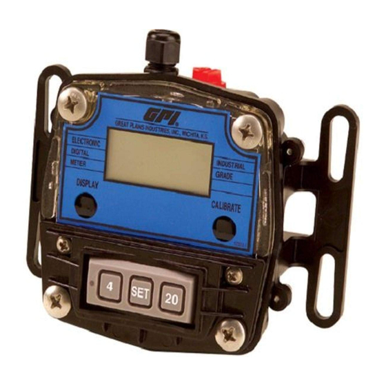
GPI 4-20 mA Out with Display
Owner's Manual
GX510
To the owner...
Congratulations on receiving your GPI 4-20 mA Out with
Display. We are pleased to provide you with a product
designed to give you maximum reliability and efficiency.
Our business is the design, manufacture, and marketing of
liquid handling, agricultural, and recreational products. We
succeed because we provide customers with innovative,
reliable, safe, timely, and competitively-priced products. We
pride ourselves in conducting our business with integrity and
professionalism.
We are proud to provide you with a quality product and the
support you need to obtain years of safe, dependable service.
President
Great Plains Industries, Inc.
Display information in this manual supersedes display information provided with your meter.
06/10
Local Models
GM Series
(Shown here on GM001)
www.gpimeters.net
1-888-996-3837
TABLE OF CONTENTS
General Information ............................................................. 2
Safety Instructions ............................................................... 2
Installation ........................................................................... 2
Wiring .................................................................................. 3
Configuration ....................................................................... 9
Operation ............................................................................. 9
Calibration ........................................................................... 9
K-Factor Method Calibration Procedures ........................... 9
Correction Factor Method Calibration Procedures ........... 10
Maintenance ...................................................................... 12
Troubleshooting ................................................................. 13
Dimensional Drawings ....................................................... 14
Illustrated Parts Drawing ................................................... 15
Specifications - Local ........................................................ 16
Specifications - Remote .................................................... 17
Service ............................................................................... 18
WEEE Directive .................................................................. 18
5252 East 36th Street North
Wichita, KS USA 67220-3205
TEL: 316-686-7361
FAX: 316-686-6746
Remote Model
GX500
Rev. H 920765-05
1
Advertisement
Table of Contents

Related Manuals for GPI GM001


Summary of Contents for GPI GM001
-
Page 1: Table Of Contents
GM Series (Shown here on GM001) To the owner… TABLE OF CONTENTS Congratulations on receiving your GPI 4-20 mA Out with General Information ............. 2 Display. We are pleased to provide you with a product Safety Instructions ............... 2 designed to give you maximum reliability and efficiency. -
Page 2: General Information
• Disconnect external power to the transmitter before litres. detaching or attaching input or output wires. • The 4-20 mA Out with Display can be used on all GPI • Ground loops between sensor and user equipment can models, including the Precision G series, the Industrial damage the transmitter and can be dangerous. -
Page 3: Wiring
This manual refers to various models of GPI flowmeters. Determine what type of input the electronics will receive and Mount the GPI 4-20 mA Out with Display using bolts, screws what type of output, if any, you require. Use the diagrams or standard U-bolts for pipes. - Page 4 Customer Equipment With Built-in Power Supply – High Temp Applications Input: Standard Remote Sensor (Variable Reluctance Pickup Coil) Output: Customer Equipment, 0-20 mA Sensing, Built-in Loop Power Supply INPUTS OUTPUTS Loop (+) GPI Meter 4-20 mA Out (current) with Display Unpowered Coil-A...
- Page 5 W I R I N G D I A G R A M 3 — 4-20 mA or 0-20 mA Output — Customer Equipment Without Built-in Power Supply Input: Turbine Mounted Display or Conditioned Signal Sensor (See inputs from Diagram 1) Standard Remote Sensor (See inputs from Diagram 2) Output: Customer Equipment, 0-20 mA Sensing, Separate Power Supply Loop Power Supply INPUTS...
-
Page 6: Pulse Output
W I R I N G D I A G R A M 5 — Pulse Output — Customer Equipment Without Built-in Power Supply Input: Turbine Mounted Display or Conditioned Signal Sensor (See inputs from Diagram 1) Standard Remote Sensor (See inputs from Diagram 2) Output: Customer Equipment, Frequency Sensing, Separate Loop Power Supply Loop Power Supply INPUTS... - Page 7 W I R I N G D I A G R A M 7 — 4-20 mA or 0-20 mA Output — Customer Equipment With Built-in Power Supply Input: Hall Effect* Output: Customer Equipment, 0-20 mA Sensing, Built-in Loop Power Supply HE Power Supply 4.5 - 24 VDC INPUTS...
- Page 8 W I R I N G D I A G R A M 9 — 0-5 V Output — Customer Equipment Without Built-in Power Supply Input: Reed Switch (See inputs from Diagram 6) or Hall Effect* (See inputs from Diagram 7) Output: Customer Equipment, 0-5 V Sensing, Separate Loop Power Supply Loop Power Supply INPUTS...
-
Page 9: Configuration
Access to the configuration settings require a specific pro- toggle through all factory set units. Other possible units cedure and a pin code available through the GPI Website at are: IGL (imperial gallon), QT (quart), CF (cubic feet), CM www.gpimeters.net or call GPI Customer Serivce at 888- (cubic meter), BL (42 gal. -
Page 10: Correction Factor Method Calibration Procedures
1 in. cally restored the next time power is applied. G_P-150 1-1/2 in. G_P-200 2 in. Procedure GM001 1/8 in. 5855 Before you start, the fluid pumping system should be ready GM002 1/4 in. 3785 to make two simple calibrating runs, first at the lowest an- GM003 1/4 in. - Page 11 NOTE: A true loop current of “0” in a loop powered device 1. Start the fluid pumping system. Set it for steady flow at like the GPI transmitter is not obtainable. That’s because the highest anticipated rate (or the rate at which you want the current loop powers the transmitter, and its operat- a “maximum”...
-
Page 12: Maintenance
• Longer (slower) response times are also appropriate in situations where sensor-output frequency fluctuates or wobbles substantially. The GPI 4-20 mA Out with Display offers a choice of five re- sponse-time settings, selectable by the unit’s pushbuttons. Procedure 1. Start with the unit unpowered. If the unit is presently operating, temporarily disable its external power supply. -
Page 13: Troubleshooting
TROUBLESHOOTING SYMPTOM PROBABLE CAUSE CORRECTIVE ACTION A. METER IS NOT 1. Field Calibration not performed properly. Field Calibrate again or select Factory Calibration. ACCURATE 2. Factory Calibration not suitable Perform a Field Calibration according to Calibration Section or for liquid being measured. select the proper Factory Calibration selection (i.e., gallon or litre). -
Page 14: Dimensional Drawings
DIMENSION DRAWINGS... -
Page 15: Illustrated Parts Drawing
901002-82 O-Ring ................1 904006-95 Screw, Hex Socket M5-0.8 x 12: 120509-01 Adapter Kit - Remote Display & Local (GM001, ....For GM005 and GM007 ..........2 GM002 & GM003) ............1 For GM010, GM015 and GM020 .........4 120509-02 Adapter Kit - Local (GM005 & GM007) ......1 120054-01 Main Circuit Assembly ............1... -
Page 16: Specifications - Local
SPECIFICATIONS – LOCAL MODEL Temperature: Ambient Temperature: +32° F to 140° F (0° C to 60° C) Applications: Cable: Use for indoor or outdoor applications where occasional No cable provided moisture is common. Mechanical Connections: Materials: Display is mounted directly to flow meter body. Acetal, Amorphous Nylon, Silicone Rubber, Polyester Electrical Connections: (decals), Viton (gasket &... -
Page 17: Specifications - Remote
0.8 V to 4.0 V range, with good linearity in over-range conditions to about 0.1 V and 4.9 V. To power some low power pickup/display devices, such as a GPI “EDM” module, a loop powered GX500 can supply 5 VDC at up to ap- Recommended minimum driven impedance = 10K Ohms. -
Page 18: Service
Please contact GPI before returning any part. It may be possible to diagnose the trouble and find a solution with a telephone call. GPI can also inform you of any special require- ments you will need to follow for shipping. - Page 20 To make a claim against this warranty, contact the GPI Customer Service Department at 316-686-7361 or 888-996-3837. Or by mail at: Great Plains Industries, Inc.
Need help?
Do you have a question about the GM001 and is the answer not in the manual?
Questions and answers