
Related Manuals for GPI 09 COMPUTER ELECTRONICS


Summary of Contents for GPI 09 COMPUTER ELECTRONICS
- Page 1 Commercial Grade 09 COMPUTER ELECTRONICS Owner’s Manual 09/11 Rev. D 920787-01 1.800.561.8187 information@itm.com www. .com...
-
Page 2: Table Of Contents
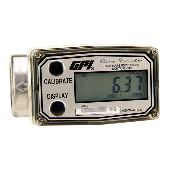
This manual will assist you in oper- self with all information about the ating and maintaining the Computer components of your GPI Electronic Electronics of the GPI Commer- Digital Meter. If you need assistance, cial Grade Meters. (See Figure 1) contact the distributor from whom you purchased your computer. -
Page 3: Installation
Product Description If you ordered the computer with These computer electronics are turbine and an accessory module, designed specifically for use on GPI please review and thoroughly un- Commercial Grade Turbine Hous- derstand all installation instructions ings. before proceeding. -
Page 4: Operation
(15.2 cm) away from motors, relays, or transformers. Activate the Meter All GPI A1 Series meters are Factory Computer is on continuously and Mutual Approved and carry a Class always ready to perform. The 1, Division 1 Approval for hazardous computer is powered by field environments. -
Page 5: Calibration
Press the DISPLAY button briefly Switching between different units will to switch between the TOTAL 1, not corrupt the Total’s contents. For TOTAL 2 BATCH and FLOWRATE example, in GL mode, the computer (if applicable). Press DISPLAY briefly totalizes 10.00 gallons, if the user to display the TOTAL 2 BATCH. -
Page 6: User Configuration
“single-point” calibration may yield acceptable accuracy when used in a non-standard application. USER CONFIGURATION Field Calibration The “09” series GPI display has been Procedures (Correction programmed with many new features, Factor Method) most of which can be enabled by the 1. -
Page 7: Maintenance
Factory and Field Calibration Curves configuration settings. This informa- are retained in the meter’s computer tion is also available on the GPI Web when power is lost. site. Configurations are entered and It is strongly recommended that stored as six-digit “codes”... -
Page 8: Troubleshooting
TROUBLESHOOTING Symptom Probable Cause Corrective Action A. METER IS NOT 1. Field Calibration not Field calibrate again or select ACCURATE performed properly Factory Calibration. 2. Factory Calibration not Perform a Field Calibration accord- suitable for liquid being ing to Calibration Section. measured 3. -
Page 9: Specifications
(-40° to +70° C) Power Input If wider operating temperature When used with Ground (J1- ranges are desired, reference 6), this has reverse polarity information on GPI Remote Kits. protection, but no on-board voltage regulation. Supplied Power: voltage must be 5.75-volts Internal DC ±5%. -
Page 10: Parts
The factory, when provided with to diagnose the trouble and identify model number and serial number, can replace your entire Computer needed parts in a telephone call. GPI Electronics Assembly. can also inform you of any special handling requirements you will need...
Need help?
Do you have a question about the 09 COMPUTER ELECTRONICS and is the answer not in the manual?
Questions and answers