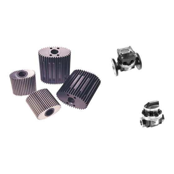
Summary of Contents for GPI GM50 series
- Page 1 Positive Displacement Flowmeters GM50 series instruction manual GM50 Pulse • GM50 Standard LCD • G540 Deluxe LCD • From serial No. CXXXX MS244G 0899 0001...
- Page 2 GM Series flow meter is suitable for both gravity and pump (in line) applications. Thank you for purchasing a GPI GM supplied. If you need further The GPI GM Series flow meters are Series Flow Meter. Please take a few...
-
Page 3: Installation
Installation Flow Inlet Bypass Line 1] GPI recommends that when setting direction of the arrows embossed on up pipework for meter installations the meter body. a bypass line be included in the Strainer design. This provides the facility for 6] The meter can be installed in any... -
Page 4: Electrical Connections
Electrical Connections Reed Switch Connections for PCB Terminals - refer Fig.3 Contact rating 15VA Configuration 1 Configuration 2 Maximum Voltage 150VDC 2 x pulse outputs Link 2 & 3 for double pulse output Hall Effect Sensor Connections - refer Fig.4 Pulse Versions Only LCD Versions 2 x Hall Effect Sensor... - Page 5 PCB (Item 5). Standard LC Display This section of the instruction manual assists you in the operating of the GPI 1] Remove the two large screws (Item Standard LC Display. Please take a few 30) and the two small screws (Item...
- Page 6 (Item 29) and gasket (Item 28). until the bottom line displays “Total 2”. Top line indicates “Preset Factory Calibration” 3] Remove battery, and clean any Cumulative Total corrosion from the battery terminals Middle (to protect terminals from corrosion The cumulative total is the total of all line or condensation coat the terminals the liquid measured since the meter’s...
-
Page 7: Meter Trouble Shooting
See “specifications” for minimum Meter reading inaccurate a] Fluid flow rate is too high or too low and maximum flow rates b] Consult GPI b] Fluid is too viscous c] Check meter body and rotors. c] Excess wear caused by incorrect Replace as required. - Page 8 Meter Parts Listing Key: u Indicates recommended Spare Parts to stock Bold text indicates Stainless Steel Model Parts Item Rec. Part or Set Part Description Parts (Order from this column only) Off. MS283F Meter Body 2” ANSI 150lb Flange (Aluminium) MS281D Meter Body 2”...
- Page 9 Display Parts Listing 23 24 25 26 28 29 Rec. Item Part or Set Part Description Parts Off. (Order from this column only) MS280S Deluxe LCD Display (Complete) MS279 Mounting Adaptor Plate MS117S Adaptor Screws MS69 LC Display Unit MS118S LC Display Mounting Screws MS127 Battery Retaining Screw...
-
Page 10: Meter Specifications
Meter Specifications Pulse Meter Type Pulse with Standard Pulse with Deluxe LC Display LC Display Flow Ranges (Litres per minute/US Gallons per minute) 15 to 350/ 4 to 92 Above 5 Centipoise 15 to 350/ 4 to 92 15 to 350/ 4 to 92 33 to 300/ 9 to 79 Below 5 Centipoise 33 to 300/ 9 to 79... -
Page 11: Meter Dimensions
Meter Dimensions GM50 Pulse Meter Dimensions GM50 Pulse Meter with Standard LC Display GM50 Pulse Meter with Deluxe LC Display... -
Page 12: Warranty
Warranty Great Plains Industries, Inc. Limited Warranty Policy Great Plains Industries, Inc., 5252 East 36th Street North, Wichita, Kansas USA 67220-3205, hereby provides a limited one year warranty against defects in material and workmanship on all products manufactured by Great Plains Industries, Inc. This warranty shall extend to the purchaser of this product and to any person to whom such product is transferred during the warranty period.


Need help?
Do you have a question about the GM50 series and is the answer not in the manual?
Questions and answers