Table of Contents
Advertisement
Advertisement
Table of Contents

Related Manuals for GCC Technologies LaserPro X252RX


Summary of Contents for GCC Technologies LaserPro X252RX
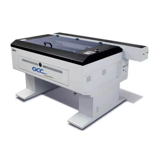
- Page 2 X380RX is backed by GCC, a truly international company that is dedicated to helping your business grow. We at GCC are proud to introduce the LaserPro X252RX & X380RX, our most economical laser engraver manufactured to date. This easy to operate machine has been designed with quality, productivity, and safety in mind.
-
Page 3: Table Of Contents
5.2.2 Color Management ................51 5.2.3 Using the LaserPro X252RX & X380RX Print Driver ......52 5.2.3.1 LaserPro X252RX & X380RX Print Driver >> Option Page ..... 53 5.2.3.2 X252RX & X380RX Print Driver >> Pen Page ......... 59 5.2.3.3 X252RX & X380RX Print Driver >> Advance Page......63 5.2.3.4 X252RX &... - Page 4 8.2.2 Cleaning the Mirrors................99 8.2.3 Removing and Cleaning the Focal Lens ........... 100 Chapter IX - Basic Troubleshooting ..............101 Chapter X - Appendix ..................102 10.1 Glossary ..................... 102 10.2 LaserPro X252RX & X380RX Specification Sheet ......103 232001240G(08)
-
Page 5: Chapter I - Safety
Even though the LaserPro X252RX & X380RX is equipped with our most powerful laser to date, proper usage and hardware safeguards make it an extremely safe machine. When the front door and back door are open, machine becomes a Class 4 equipment and users must wear goggles to operate the machine. - Page 6 In compliance with CDRH standards, the required warning labels are affixed at the time of manufacture to the LaserPro X252RX & X380RX in the appropriate locations. These labels are not to be modified in any way or removed for any reason. Please familiarize yourself with the specific labels and their locations on the machine.
- Page 7 CDRH Label This label indicates the class level of CDRH. 232001240G(08)
- Page 8 CE Label This label identifies the classification of the Model in accordance with IEC 60825-1. It is located on the rear of the machine’s cabinet. Laser Path Warning Label LaserPro machines are very safe under normal function. However, in case of any accident, Laser Path Warning Label will be stick on the possible laser path.
- Page 9 Aperture warning stickers (mirror): This label indicates the laser path. Normally you can find this label inside of machine or laser exit. Please take extra caution of this area when you conduct maintenance or operate machine. Protection Window Label This label indicates the protection wavelength. You can find this label in the lower right corner of window.
-
Page 10: Safety Measures
1.5 Safety Measures LASER RADIATION WARNING: Exposure to laser radiation may result in physical burns and severe eye damage. Proper use and regular maintenance of this machine is important to the safety of all people in the immediate area. Prior to operation, carefully read and familiarize yourself with the warning labels located on both your laser system and in this manual. -
Page 11: Operating Environment
1.6 Operating Environment Please follow the guidelines when considering a suitable location to set the LaserPro X252RX & X380RX. Improper work environments may lead to operational malfunction and/or unsafe working conditions. The LaserPro X252RX & X380RX should be placed and operated in a standard office-type environment. -
Page 12: Ec-Declaration Of Conformity
1.7 EC-Declaration of conformity 232001240G(08) -
Page 13: Chapter Ii - Unpacking & Contents
Chapter II - Unpacking & Contents 2.1 Unloading and Unpacking The LaserPro X252RX & X380RX is shipped in one crate that contains the machine, the software, and all of the necessary accessories. The following section contains detailed step- by-step instructions for unpacking and assembly of the machine. - Page 14 Safety Harnesses 5) Unscrew the screws holding the spacers (left and right side of the machine) and the step board (front and rear of the machine). Remove the two spacers and the step board. Spacer Step Board 232001240G(08)
- Page 15 6) With the removed left / right sideboard of crate, place one against the left or right side of the shipping crate to form an incline. Place the step board against the inclined sideboard to form a complete ramp. Step Board Side Board 7) Carefully roll the machine off the shipping crate and position it into your work area 232001240G(08)
-
Page 16: Contents And Accessories Checklist
2.2 Contents and Accessories Checklist Please check to make sure that all of the following items are included within the shipping crate. If any of the following items are missing, immediately contact your local GCC distributor. ITEM QUANTITY Cleaning Kit: Cotton swab Lens Cleaner Solution Lens Tissue... -
Page 17: Chapter Iii - Mechanical Overview
Chapter III - Mechanical Overview Please take some time to familiarize yourself with this section regarding the mechanical overview of the LaserPro X252RX & X380RX. References will be made back to the different parts of the LaserPro X252RX & X380RX in later sections. -
Page 18: Right (Profile) View
3.3 Right (Profile) View Power ON/OFF Switch USB Port Error Indicators Power Cable Inlet Print Port 3.4 Left (Profile) View Access Panel Mirror #1 232001240G(08) -
Page 19: Rear View
3.5 Rear View Laser Compartment Laser Compartment Handles Handles SmartEXT™ Pass-Through (Rear) Water Inlet and outlet Ventilation Opening 232001240G(08) -
Page 20: Chapter Iv - Setup And Installation
Chapter IV - Setup and Installation 4.1 Machine Setup 4.1.1 Water Chiller Installation Always turn on the water chiller before turning on the machine. Connect the water hoses between the machine and the water chiller. Make sure the hoses are connected correctly with the right water flow directions. - Page 21 1. The water chiller comes with two orange color water tubes 2. Connect the tubes to the machine. Connect the tube to the “Water Out” opening and the “Water In” openings. 3. Connect the tubes to the water chiller system. ●It is recommended to change the cooling water once every month.
-
Page 22: Connecting The Peripherals
NOTE De-ionized water is recommended as the coolant. Propylene glycol can be used as an anti- freeze agent. The coolant used with the water chiller should have the following properties: • Good heat conduction and low viscosity • Anti dirt forming •... -
Page 23: Powering Up The Machine
4.1.4 Connecting the Computer The LaserPro X252RX & X380RX can communicate with a computer through a USB Port or Parallel Printer Port connection interface. The USB Port connection offers faster file transfer rates and greater flexibility over the Parallel Printer Port connection. Regardless of the connectivity method chosen, you will need to connect the respective connection cable from the LaserPro X252RX &... -
Page 24: Recommended Computer Configuration
Next to continue. 4) At the Select a Printer Port page, select <Use the following port> and select the port that the LaserPro X252RX & X380RX will be attached to, then click Next to continue. 5) The next screen will prompt you with a list to select the manufacturer and model of your printer. -
Page 25: Parallels Desktops For Mac Os Users
At the Printer Sharing screen, select <Do not share this printer> and click Next to continue. 10) Select <No> when asked if you want to print a test page and click Next to continue. 11) Now the installation will proceed, if you get a Hardware Warning about the software you are installing for this hardware has not passed Windows Logo testing…... - Page 26 4) Enter your Mac OS X User Name and Password then press “OK” 5) Press “Active” 232001240G(08)
- Page 27 6) Press “OK” when activation is complete. 232001240G(08)
- Page 28 7) Register Parallels Desktop 8) Press “Register” and “OK” to complete the installation of Parallels Desktop. 9) Open Parallels Desktop (in the Applications folder) then choose File → New 232001240G(08)
- Page 29 10) Press “Install Windows from DVD or image file” then press “continue” to install windows OS 11) Select CD-ROM drive with the Windows installation CD 12) Enter the Windows OS product key 232001240G(08)
- Page 30 13) Select how you would like to run your Windows program 14) After the prior setting is complete the windows OS installation procedure will start automatically. 15) Windows OS installation is complete then you can refer to “4.2.5 Installation of the LaserPro Print Driver”...
- Page 31 4.2.4 Using Autodesk Inventor with GCC LaserPro machine 1. Start drawing. 2. Delete border and title block by right clicking on sheet1 and selecting delete. 3. Set sheet size to match working area of engraver. Engraver working area can be found 232001240G(08)
- Page 32 on the paper tab of the windows driver. 4. Start sketch. 5. Engraving a. Finish sketch. b. Right click on sketch and select properties. c. Line Type: By Layer d. Line Weight: By Layer e. Set color to match one of the 16 colors available in the pen tab of the windows driver.
- Page 33 6. Cutting a. Finish sketch. b. Right click on sketch and select properties. c. Line Type: Continuous d. Line Weight: .001 in. e. Set color to match one of the 16 colors available in the pen tab of the windows driver.
-
Page 34: Using Ecut Plug-In With Gcc Laser Machine
NOTE All objects created in one particular sketch will have the same properties meaning all will engrave or all will cut. If you would like to engrave and cut in the same job you will need at least two sketches, one with all the engravings and another with all the cuts, to do so properly. -
Page 35: Chapter V - Operating The Laserpro X252Rx & X380Rx
Once you have installed the LaserPro USB Driver (USB connectivity only), LaserPro Print Driver, and have connected the LaserPro X252RX & X380RX to your computer, you will need to familiarize yourself with the LaserPro X252RX & X380RX’s control panel and LaserPro Print Driver. -
Page 36: Graphic Control Panel Overview (Description)
5.1.3 Graphic Control Panel Overview (Description) The Control Panel The control panel on the LaserPro X252RX & X380RX provides easy access to all of the manual controls needed for cutting. The liquid crystal display (LCD), functional, directional and selection buttons make navigating through the machine’s manual controls easy to do. - Page 37 Function (F1 / F2 / F3 / F4) – Four function buttons allow you to select various functions, which will change depending on what section of the menu you are in. Each function button’s corresponding function will be displayed right above its respective button on the LCD display screen.
-
Page 38: Graphic Control Panel Navigation Chart
5.1.4 Graphic Control Panel Navigation Chart Carriage / Work Table Main Work Page Adjustment Page Functions Page File Management Page Machine Information Page Machine Setting Page Link / DLink Page Set Lens Page File Information Page Tune Auto Focus Page Set Red Beam Page File Management Edit Page... -
Page 39: Graphic Control Panel Function
Main Work Page The main work page is the page that the LaserPro X252RX & X380RX will default to upon startup and will be the “home base” for when navigating through the various functions of the control panel. This will be the page that is displayed when you are processing your jobs. This page contains specific job information such as the current job’s name, Speed, Power, PPI, DPI, processing /... - Page 40 Carriage / Work Table Adjustment Page ☼ navigating to this page: Main Work Page Press , or F3 Carriage / Work Table Adjustment Page The Carriage / Work Table Adjustment Page allow you to manually increase and decrease the height of the work table (Z-axis). In addition, you can manually adjust the Y-axis and X-axis of the laser carriage.
- Page 41 File Management Page – this page allows you to manage the files that you have loaded onto the LaserPro X252RX & X380RX. Machine Setting Page – this page allows you to access and modify a variety of your machine...
- Page 42 The File Management Page allows you to manage the files that you have loaded onto the LaserPro X252RX & X380RX. You can scroll through your jobs, delete a selected job, delete all jobs, and go to the Link/DLink Page to set and arrange multiple loaded jobs into a single job queue for processing.
- Page 43 Link/DLink Page ☼ Navigating to this page: Main Work Page Press F4 Functions Page Select <File Management> from the menu File Management Page Press F2 Link / DLink Page The Link/DLink Page allows you to set, arrange, and remove loaded jobs to and from a job queue for processing.
- Page 44 File Information Page ☼ Navigating to this page: Main Work Page Press F4 Functions Page Select <File Management> from the menu File Management Page Select a job file and press Enter File Information Page The File Information Page allows you to view the speed, power, DPI, and PPI settings of the selected job.
- Page 45 File Management Edit Page ☼ Navigating to this page: Main Work Page Press F4 Functions Page Select <File Management> from the menu File Management Page Select a job file and press Enter File Information Page Press F4 File Management Edit Page The File Management Edit Page allows choosing to modify your raster or vector settings for the selected job, as well as setting the number of times to repeatedly process the selected job (Repeat Num).
- Page 46 PPI, and power ramp settings for the selected job. These settings correspond to the same settings found on the LaserPro X252RX & X380RX print driver. This page allows you to easily adjust these values to make immediate adjustments while processing your loaded jobs, even when you have disconnected your computer from the LaserPro X252RX &...
- Page 47 Machine Setting Page ☼ Navigating to this page: Main Work Page Press F4 Functions Page Select <Machine Setting> from the menu Machine Setting Page The Machine Setting Page allows you to access and modify a variety of your machine settings, including: Set Lens, Tune Auto Focus, Set Table Down, Set Red Beam, Carriage Lock, Set Command Mode, Save Position, Flash Memory, Set File Save Mode, Set Vector Mode, Tune Image Power, Set Laser Wattage, Set Fine Mode, Other, Reset.
- Page 48 Remember to save your settings after you have made the proper changes. Now by pressing the Auto Focus button, the LaserPro X252RX & X380RX will auto focus properly using the new lens setting. The LaserPro X252RX & X380RX’s default setting is <2.0”>...
- Page 49 Tune Auto Focus Page ☼ Navigating to this page: Main Work Page Press F4 Functions Page Select <Machine Setting> from the menu Machine Setting Page Select <Tune Auto Focus> from the menu Tune Auto Focus Page The Tune Auto Focus Page allows you to manually set the default auto focus distance / vertical height of the worktable (Z-axis) for when the Auto Focus button is pushed.
- Page 50 Pressing the Enter key at this point will confirm the prompt to move the work table to its lowest position. If the Table Down is set to <NO>, then the LaserPro X252RX & X380RX will not display this warning prompt at system startup.
- Page 51 ☼ Navigating to this page: Set Red Beam Page Main Work Page Press F4 Functions Page Select <Machine Setting> from the menu Machine Setting Page Select <Set Red Beam> from the menu Set Red Beam Page The Set Beam Page allows you to turn on or off the red dot laser pointer on the laser carriage. Enabling this function will indicate the exact location where the laser will fire upon.
- Page 52 ☼ Navigating to this page: Carriage Free Page Main Work Page Press F4 Functions Page Select <Machine Setting> from the menu Machine Setting Page Select <Carriage Free> from the menu Carriage Free Page The Carriage Free Page allows you to set whether the laser carriage is locked or free. If the Carriage Free setting is set to <YES>, then you will be able to manually move the laser carriage along the X and Y axis by hand with the top door open.
- Page 53 ☼ Navigating to this page: Set Command Mode Page Main Work Page Press F4 Functions Page Select <Machine Setting> from the menu Machine Setting Page Select <Set Command Mode > from the menu Set Command Mode Page The Set Command Mode Page allows you to configure vector settings when outputting in Default or HPGL mode.
- Page 54 ☼ Navigating to this page: Save Position Function Main Work Page Press F4 Functions Page Select <Machine Setting> from the menu Machine Setting Page Select <Save Position > from the menu The Save Position Function allows you to save the current X-axis and Y-axis positions of the laser carriage and sets this position to be the origin for subsequent jobs.
- Page 55 Set File Save Mode Page The Set File Save Mode Page allows you to set whether or not the LaserPro X252RX & X380RX automatically deletes each job file after processing. Setting File Save to <NO> will automatically and immediately delete each job file from the LaserPro X252RX & X380RX after the cutting process.
- Page 56 SmartGUARD Page ☼ Navigating to this page: Main Work Page Press F4 Functions Page Select <Machine Setting> from the menu Machine Setting Page Select <SmartGUARD> from the menu Set File Save Mode Page After hardware installation, please enter the function menu on the control panel to enable the SmartGUARD fire alarm.
- Page 57 ☼ Navigating to this page: Other Page Main Work Page Press F4 Functions Page Select <Machine Setting> from the menu Machine Setting Page Select <Other> from the menu Other Page LaserPro X252 & X380RX User Manual - 46 -...
- Page 58 The Other Page allows you to change various settings relating to the control panel. The Language setting will allow changing available languages displayed by the control panel. The Unit setting will allow you to chance whether the units displayed by the control panel is in the metric or imperial system. The EOF (end of file) Alarm setting will enable or disable an audible notification when your jobs are complete.
- Page 59 Reset Page The Reset Page allows you to reset all changes made to the LaserPro X252RX & X380RX’s Machine Settings Page to their default settings. This does not affect the settings saved to an image file on the computer. The User Reset setting will set all settings back to the default.
- Page 60 Machine Information Page ☼ Navigating to this page: Main Work Page Press F4 Functions Page Select <Machine Information> from the menu Machine Information Page The Machine Information Page allows you to view information regarding the system such as the GCC logo, machine name, firmware version, and other information.
-
Page 61: The Laserpro X252Rx & X380Rx Print Driver
If LaserPro X252RX & X380RX is not selected as DEFAULT PRINTER, you may set it up through the graphics software as well. The following is taking Corel Draw as example of how to set up LaserPro X252RX & X380RX as the Printer. -
Page 62: Color Management
LaserPro driver uses pen color settings to control laser cutting parameters. In addition to having your Page Setup and Orientation properly set in your graphics software, you will also need to make sure Color Management is DISABLED prior to working with the LaserPro X252RX & X380RX Print Driver. If you do not properly From your graphic software’s Color Management page:... -
Page 63: Using The Laserpro X252Rx & X380Rx Print Driver
Now after you have properly set the Page and Layout and Color Management of your graphics software, you are ready to configure the details of your actual job through the LaserPro X252RX & X380RX Print Driver. The LaserPro X252RX & X380RX print driver allows you to adjust your cutting options. After you have setup your image, design, or text to be processed in your software application, you can access the LaserPro X252RX &... -
Page 64: Laserpro X252Rx & X380Rx Print Driver >> Option Page
Note For this screenshot example, CorelDraw was used as the software application. The LaserPro X252RX & X380RX Print Driver consists of seven primary sections (pages) in which you will be able to choose various cutting options and settings: Option Page... - Page 65 Black & White mode. NOTE Selecting the Black & White mode will enable the Raster page on the LaserPro X252RX/ X380RX Print Driver, allowing you to adjust advanced stamp-related settings. Manual Color Fill: Select this mode when you would like to designate specific power and speed settings and link them to certain colors of your image.
- Page 66 Lower DPI settings result in coarser and shallower engravings, but require less time to complete. The LaserPro X252RX/ X380RX Series offers 8 DPI options: 125, 250, 300, 380, 500, 600, 760, and 1000 experiment with different settings to get your desired effect.
- Page 67 Print from your graphic software program. If Print Immediately is not checked, then selecting Print will transfer the job file to the LaserPro X252RX/ X380RX Series system and will need to be initialized from the LaserPro X252RX/ X380RX Series control panel.
- Page 68 User will be prompted to enter a filename After entering the filename and pressing “ok”, the Preview screen will be shown. 232001240G(08)
- Page 69 The output file can be previewed and a simulated working time of the job is also displayed. File Function (Options Page): The file function section allows you to manage various laser parameters. This section is useful when performing duplicate jobs on a variety of objects, allowing you to save your frequently used laser parameters and load them in the future.
-
Page 70: X252Rx & X380Rx Print Driver >> Pen Page
5.2.3.2 X252RX & X380RX Print Driver >> Pen Page The LaserPro X252RX & X380RX incorporates the use of 16 different colors to represent 16 different laser power and speed settings when cutting. These colors are referred to as “Pens”. Think of each pen as a designated laser setting, rather than as a color. - Page 71 If you would like to specify your own colors to designate to a particular laser setting, then all you have to do is to double-click on that particular pen color from the pen menu and a color manager window will open where you can select “define custom colors”...
- Page 72 Cutting / engraving depth and quality are determined by a combination of power and speed. Slower speeds at higher power will produce deeper cuts and engravings, whereas higher speeds at lower power will produce more shallow cuts and engravings. Power (Pen Page) [DEFAULT SETTING: 50] The power slider controls the laser’s power during operation (engraving power) with a range setting from 0 –...
- Page 73 Air (Pen Page) [DEFAULT SETTING: Unselected] This checkbox controls the SmartAIR air-assist function (if you have the optional air compressor installed). By selecting a pen color and checking this box will enable the SmartAIR air-assist function for that particular pen color. As an example, if you are performing a combination of both surface raster engraving job and deep vector cutting on a material such as acrylic, you may want to enable the SmartAIR air-assist for the vector cutting sections to get the cleanest cuts.
-
Page 74: X252Rx & X380Rx Print Driver >> Advance Page
5.2.3.3 X252RX & X380RX Print Driver >> Advance Page Scaling (Advanced Page) [DEFAULT SETTING: 0] In some cases you may find a slight output inaccuracy in the actual output compared to what you have set in the computer. This margin of error or offset is extremely small (approximately 1/300). What this means is that there may be a 1-unit offset for every 300 unit increments. - Page 75 • SmartCENTER: The SmartCENTER mode is an enhanced version of the center mode and will determine the center point between two/four positions. User can pinpoint and save two or four distinct points by moving the pen carriage and using the red beam as a reference. When this mode is selected, the machine will prompt the user to move the lens carriage to store the location of the first position and then prompt the user to move the lens carriage again to store a second position or continue to a 3rd and a 4th position depending on whether the 2-point mode is...
- Page 76 This mode is useful for engraving rubber stamps, as it allows you to create the outline around your stamp image. NOTE If you wish to use the Border and Cluster function simultaneously, then the Border Thickness value must be less than the Distance value specified in the Cluster setting. Vector Function (Advanced Page) [DEFAULT SETTING: Normal] •...
-
Page 77: X252Rx & X380Rx Print Driver >> Paper Page
This setting allows you to improve the cutting quality at the expense of speed. Your engraving speed will be dropped by 50%, to maximize the cutting power. We recommend that you enable this function when cutting thicker materials. 5.2.3.4 X252RX & X380RX Print Driver >> Paper Page Paper Size (Paper Page) The paper size represents your total work area. - Page 78 protruding lines are from the square’s ideal edge, the larger you will need to set the Image Tuning value to compensate. Square’s Left Edge Square’s Right Edge The following is an example that has the proper image tuning, and demonstrates this significance when engraving fine, small, intricate text.
-
Page 79: X252Rx & X380Rx Print Driver >> Language Page
5.2.3.5 X252RX & X380RX Print Driver >> Language Page This page allows you specify the language displayed by the X252RX & X380RX Print Driver. Current language options allow for: English, Spanish, French, And Chinese (Simplified, Traditional), Japanese, and German. 5.2.3.6 X252RX & X380RX Print Driver >> Raster Page NOTE The Raster Page is only available when Black &... - Page 80 Contrast (Raster Page) [DEFAULT SETTING: 0] This provides a quick and easy way to immediately adjust the contrast of an engraved image. Moving the slider to the Dark setting will increase the contrast levels of the engraved output, whereas moving the slider to the Light setting will decrease the contrast levels of the engraved output.
-
Page 81: X252Rx & X380Rx Print Driver >> Stamp Page
o Enhance Dithering [DEFAULT SETTING: Unselected] Selecting this will produce a finer dithering output. Error Diffusion (Raster Page) Interprets and outputs the raster engraving via the error diffusion method. This mode will allow you to select from three diffusion types: Floyd, Stucki, and Jarvis. [DEFAULT SETTING: Floyd] o Diffusion Type: Floyd, Stucki, Jarvis Each diffusion type presents the shade of image as different spread halftones instead of dots to... - Page 82 Adjustment Bar/ Power Level (Stamp Page) Another important aspect of creating a stamp is setting the slope level of the shoulder. The shoulder is the section from the “contact section” of the stamp to its base. This function allows you to adjust the slope for the shoulder sections of your stamp. By sliding the sliders or directly input of power levels, you will be able to change the slope of the shoulder.
-
Page 83: Chapter Vi - Cutting Techniques
The LaserPro X252RX & X380RX Print Driver determines vector cut based on the outline width of that particular area or section of the design. In order to prep a particular section for vector cutting, you will need to set that object’s fill color to white and set its outline thickness between 0.001”... -
Page 84: Vector And Raster
Below is an example of how to prep an area (in this case, we will use a section of text) for vector cutting. CorelDraw will be used as the selected graphics software. 1) With the text function, create a string of characters and select those characters by clicking on the text. 2) Change the text fill color of the selected characters to white by left clicking on the white color from the CorelDraw Color Palette (located on the right hand side of the screen). - Page 85 3D processing uses degrees of the gray level to adjust the output energy of the laser. Take the figures below as an example. When the color of a certain block is set as 100% black, the laser output energy for processing will be at 100%.
- Page 86 Photoshop & CorelDRAW The way to produce 3D graphics with Photoshop and CorelDRAW is very similar. Fill in the desired gray level colors to each of the drawn figures, and proceed with further arrangement and combination. Then you may output the 3D graphic to the laser for the production of the 3D object.
- Page 87 232001240G(08)
- Page 88 LaserPro requests your attention If you need to produce circular 3D graphics, you only need to select Radial as the gray level type in the pull-down menu of Type. Then, a circular 3D graphic may be produced. Step 2. Produce three-dimensional characters 232001240G(08)
- Page 89 232001240G(08)
- Page 90 Step 3. Edit the characters for the website Step 4. Combine the 3D images After finishing the production for each of the objects, you may proceed with the combination of the objects. The combined graphic may be output with the laser engraver. Output the 3D graphic After selecting the graphic to be output, set the Mode as 3D Mode in the driver.
- Page 91 Tips for engraving 3D graphics LaserPro Application Lab provides a few reminders that may require your attention during the 3D engraving in order to improve the result of the engraving. Turn on the Air Assist function When the engraving is done along with Air Assist, the depth of the engraving would be deeper. Set Air assist inside the driver by checking the box.
-
Page 92: Modify Image Settings Of A Picture For Better Engraving Quality
6.5 Modify Image Settings of A Picture for Better Engraving Quality Connect your digital camera to the computer by USB cable. Download the picture from the digital camera to the computer Select the picture that you want to engrave. Import the image from the folder where the picture is located by selecting File/Import Convert the image to Bitmap by selecting the image and click on Bitmaps/Convert to Bitmap 232001240G(08) - Page 93 Change the Bitmap settings by setting “Color” to Grayscale (8-bit) and “Resolution” to 300 dpi and click OK. Finally, Invert the image by selecting Effects/Transform/Invert 232001240G(08)
- Page 94 Now you are ready to output the modified image by clicking File/Print 232001240G(08)
- Page 95 NOTE This instruction is a simple example for general use. There are many tips and tricks to achieve a good engraving quality. It takes a lot of practice and experience to achieve a good engraving quality. Different picture may need different modifications and different material may need different parameters.
-
Page 96: Chapter Vii - Optional Items
Chapter VII - Optional Items When purchasing the LaserPro X252RX & X380RX from your local authorized GCC distributor, you will be provided a chance to purchase optional items to enhance your experience with your system. If anytime after the purchase of your X252RX & X380RX, would you like to purchase any optional item, please contact your local authorized GCC distributor. -
Page 97: Air Compressor Option (220V Only)
7.2 Air Compressor Option (220V Only) Specifically designed for laser engravers, the air compressor utilizes an oil-free diaphragm. The air compressor helps eliminate harmful and potentially damaging moisture from the laser optics, maximizing laser optic life. In addition the air compressor provides the optimal air flow to the SmartAIR nozzles to minimize flaming, suppress working temperatures, and blow away dust and particle byproducts generated from the laser process. - Page 98 5) Take the unattached end of the ¼” air tubing (other end already connected to air compressor) and connect it to the air tube connector on the air assist valve. Make sure you press down on the air tube fastener when inserting the ¼” air tubing, to form a tight, secure attachment as indicated in the diagram below.
-
Page 99: Smartbox Option
LaserPro X252RX & X380RX print driver and hardware control panel. Please refer to the LaserPro X252RX & X380RX PEN page on print driver section of this manual for details on how to enable and configure air-assist functionalities. - Page 100 1) In order to use the cutting box along with the material support stands, you must first remove the honeycomb table from the cutting box. Before you position the cutting box in the LaserPro X252RX & X380RX, first unscrew the screws that attach the hinges of the honeycomb table to the cutting box.
-
Page 101: Smartair Fine / Ultra Nozzles Option
(as shown in the picture below). This allows the LaserPro X252RX & X380RX to properly account for the extra height the cutting table adds to the cutting table. -
Page 102: Rotary Attachment Option
LaserPro X252RX & X380RX print driver and hardware control panel. Please refer to the LaserPro X252RX & X380RX print driver and graphic control panel sections of this manual for details on how to enable and configure air-assist functionalities. - Page 103 Exchange the Conical Fixtures: A. Remove the 2 screws shown in the picture below. B. Detach the circular cylindrical cone by moving it in the direction of the arrow as shown below. C. Assemble the smaller conical fixture onto the rotary attachment as shown below. 232001240G(08)
- Page 104 D. Use the flat surface as shown in picture below as a reference point and tighten the first screw against it. After doing so, tighten the second screw and the rotary attachment is ready for use. Flat surface 1. Tighten this against the flat surface 2.
- Page 105 OPERATION: 1) Use a ruler to measure the diameter (at the point on the work piece you will be engraving) and length of the work piece you will be engraving. Make a record of this. 2) Load the work piece onto the rotary attachment by first listing the lever on the rotary attachment, unlocking the adjustable end of the rotary attachment.
-
Page 106: Chapter Viii Basic Maintenance
Chapter VIII Basic Maintenance Keeping your LaserPro X252RX & X380RX clean and well maintained will ensure quality output, consistent reliability, and extended product life. Smoke, dust or residue build-up inside the laser system or the mechanical components can cause a reduction in the laser power, irregularities in the motion system, reduced product life cycle, and a host of other avoidable problems. -
Page 107: Maintaining The Worktable And Motion System
Eclipse Cleaning System Solution 8.2 Maintaining the Worktable and Motion System 8.2.1 Accessing the Worktable and Motion System Remove the screws of the top of the machine and lift the top off. 8.2.2 Cleaning the Worktable and Motion System 8.2.2.1 Cleaning the Worktable and Motion System Clean the working table and the motion system on a weekly basis through the following steps: 1) Turn the power off and unplug the X252RX &... -
Page 108: Lubrication Of The X / Y Rails
Mirror 1 This mirror is located inside the laser cabinet of the LaserPro X252RX & X380RX. 1) Use a #2 Phillips Screwdriver to open the rear laser cabinet of the LaserPro X252RX & X380RX. 2) Loosen the thumbscrew and remove the dust cover securing the mirror. (As shown in the picture below). - Page 109 4) Re-install the mirror after cleaning. 5) Tighten the thumbscrew. 6) Replace and secure the outer access panel. Mirror 2, 3, 4 These mirrors are located in the worktable area of the LaserPro X252RX & X380RX. Mirror 2 Mirror 3 Mirror 4...
-
Page 110: Cleaning The Mirrors
Mirror 2 1) Unscrew and remove the black dust cover covering mirror 2. 2) Unscrew the thumbscrew holding mirror 2 in place. 3) Clean the lens in the proper manner. 4) Re-install mirror 2 after cleaning. 5) Tighten the thumbscrew. 6) Replace and secure the black dust cover. -
Page 111: Removing And Cleaning The Focal Lens
6) Make sure that the mirror is completely dry before reinstalling it. CAUTION • If the center of the mirror is scratched, contact your LaserPro X252RX & X380RX dealer for a replacement. 8.2.3 Removing and Cleaning the Focal Lens 1) Unscrew the three thumbscrews (front face of the laser head) securing the laser carriage panel and remove the laser carriage panel to reveal the focal lens. -
Page 112: Chapter Ix - Basic Troubleshooting
Chapter IX - Basic Troubleshooting Quality Problems Check focal length setting under F4 function key-> Machine Setting-> Set Focus Lens to see if it matches the type of the lens installed. Check if the focal Lens is installed correctly or if focal Lens is not fixed properly. Check if it is caused by the debris or dust builds up in the bearing tracks or x rail. -
Page 113: Glossary
Chapter X - Appendix 10.1 Glossary Color Fill – Term within the awards and engraving industry used to describe the variety of techniques used to add color or contrast to engraving. DPI – Dots Per Inch or Pixels Per Inch. The resolution of an image as defined by the amount of dots/pixels included in an inch. -
Page 114: Laserpro X252Rx & X380Rx Specification Sheet
10.2 LaserPro X252RX & X380RX Specification Sheet X252RX & X380RX Models X252RX & X380RXRX Wattage 100W Laser source Sealed CO2 Laser Cooling Water Cool Working Area 25 x 18 in. (6350 x 458 mm) All doors closed 27 x 19 x 6.5 in. (685 x 482 x 165 mm) Max. - Page 115 X380RX Models X380RXRX Wattage 100W Laser source Sealed CO2 Laser Cooling Water Cool Working Area 38 x 24 in. (960 x 610 mm) All doors closed 41 x 25 x 6.5 in. (1041 x 635 x 165 mm) Max. Part Size (WxLxH) 41 x ∞...
Need help?
Do you have a question about the LaserPro X252RX and is the answer not in the manual?
Questions and answers