Table of Contents
Advertisement
Quick Links
Advertisement
Table of Contents

Related Manuals for GCC Technologies LabelExpress


Summary of Contents for GCC Technologies LabelExpress
- Page 1 LabelExpress / DecalExpress User Manual v.9.0...
- Page 2 Dear Sir / Madam, Thank you for choosing GCC and the LABELEXPRESS/DECALEXPRESS. You can be assured that this machine meets the highest safety standards while using technological innovations shared by no other digital laser finisher. LABELEXPRESS/DECALEXPRESS is backed by GCC, a truly international company that is dedicated to help your business grow.
- Page 3 New version Add 24” machine overview Revise 4.1.1 Roll media installation Add safety description in specification sheet Change the name from LabelExpress(including 15” & 24”) to LabelExpress(15”) & DecalExpress(24”) Change the name from LabelExpress/DecalExpress to LABELLASER/DECALLASER Change the name from LABERLASER/DECALLASER to LableExpress/DecalExpress Add DECAL –...
-
Page 4: Table Of Contents
Table of Contents Chapter 1 Safety ..................1 Principles of a CO Laser ................2 Safety Ratings ....................2 The safety interlock System ................. 2 The safety Labels ..................3 Safety Measures .................... 7 1.5.1 General Safety ....................7 1.5.2 Safety Notice for Class 4 Machine ............9 Operating Environment ................ - Page 5 Operating SmartCONTROL Label ............97 5.3.7 CCD Light Adjustment ................105 5.3.8 LabelExpress / DecalExpress Sample Book Suggested Parameters107 Chapter 6 Basic Maintenance ............. 109 Suggested Cleaning and Maintenance Supplies ....... 110 Maintaining the Work area and Motion System ......... 111 6.2.1 Cleaning the Work Area and Motion System .........
- Page 6 Specification Sheet ......... 117 GCC LABEL EXPRESS GCC DECAL EXPRESS Specification Sheet ..........118 Date to Release: 13 May 2021 www.GCCworld.com LABEL EXPRESS / DECAL EXPRESS User Manual...
-
Page 7: Chapter 1 Safety
Chapter Safety Principles of Laser Safety Ratings Safety Labels The Safety Interlock System Safety Measures Operating Environment www.GCCworld.com LABEL EXPRESS / DECAL EXPRESS User Manual... -
Page 8: Principles Of A Co Laser
One of the key safety features found on the LABELEXPRESS/DECALEXPRESS is a Class 4 red beam safety guidance pointer (similar to a laser-pointer presentation pen) allowing the operator to see the exact location where the laser beam will fire. -
Page 9: The Safety Labels
In compliance with CDRH standards, the required warning labels are affixed at the time of manufacture to the GCC LABELEXPRESS/DECALEXPRESS Series in the appropriate locations. These labels are not to be modified in any way or removed for any reason. Please familiarize yourself with the specific labels and their locations on the machine. - Page 10 XXXXXX XXXXXX www.GCCworld.com LABEL EXPRESS / DECAL EXPRESS User Manual...
- Page 11 CDRH Label This label indicates the class level of CDRH. CE Label This label indicates the class level of CE. Warning Label Warning Label shows all the necessary information to be aware of during operation. Laser Path Warning Label The machines are very safe under normal functioning conditions. However, in case of any accident, Laser Path Warning Label will be affixed on the possible laser path.
- Page 12 Emergency Stop Label This label indicates the emergency stop button. You can find this label on the right upper side of the machine. Aperture warning stickers (mirror): This label indicates the laser path. Normally you can find this label inside of machine or laser exit.
-
Page 13: Safety Measures
Avoid hands being engaged in rotating gears Cutting Hazard Warning Label Avoid hands being cut severely by sharp blade. Laser Hazard Warning Label Avoid exposure laser radiation is emitted from this aperture. Safety Measures 1.5.1 General Safety • LASER RADIATION WARNING: Exposure to laser radiation may result in burns to the skin and can cause severe eye damage. - Page 14 and operational smoke or fire detector should be kept in the vicinity of the machine. • Caution—Use of controls or adjustments or performance of procedures other than those specified herein may result in hazardous radiation exposure. • Resulting debris from laser cutting are very dangerous and may cause fire hazard. DO NOT leave debris and scraps inside laser machine after job finished.
-
Page 15: Safety Notice For Class 4 Machine
• Ensure the immediate work area of the machine is well-ventilated. Odors, vapors, and dust are by products generated during the laser engraving and cutting process. An exhaust system and vacuum cutting box are recommended. Please contact GCC or your local GCC distributor for more information. •... -
Page 16: Operating Environment
Please follow the guidelines when considering a suitable location to set the LABELEXPRESS/DECALEXPRESS Series. Improper work environment may lead to operational malfunction and/or unsafe working conditions. The LABELEXPRESS/DECALEXPRESS Series should be placed and operated in a standard office-type environment. ... - Page 17 Make sure your smoke or fire detection system in the immediate area is functioning. Setup the machine to be apart from the wall for at least 60 cm (2 feet). www.GCCworld.com LABEL EXPRESS / DECAL EXPRESS User Manual...
-
Page 18: Chapter 2 Unpacking & Contents
Contents and Accessories Checklist Unloading and Unpacking The LABELEXPRESS/DECALEXPRESS Series is shipped in one crate that contains the machine, the software, and all of the necessary accessories. The following section shows detailed step-by-step instructions for unpacking and assembly of the machine. - Page 19 NOTE: It requires minimum 2 people to move the machine and make sure there is at least 3 meters space to allow the LABELEXPRESS/DECALEXPRESS to be moved from the packing box to the working area. Make sure to move the LABELEXPRESS/DECALEXPRESS to the working area from the front side of the machine.
- Page 20 Step 3: Use a flathead screwdriver to remove the brackets on the four corners of the crate. Step 5: Pull the front panel and lower it to an angle of about 45 degrees and then pull it away www.GCCworld.com LABEL EXPRESS / DECAL EXPRESS User Manual...
- Page 21 from the crate. Do the same for the rear panel. Remove the left and right panels in the same way after the front and rear panels have been removed. Step 6: Unbuckle and remove the belts that holds the machine in place. www.GCCworld.com LABEL EXPRESS / DECAL EXPRESS User Manual...
- Page 22 Step 7: Use a Phillips screwdriver to remove the brackets that holds the machine in place. Step 8: Place the ramps as shown below and adjust the leg-glide to the uppermost position with a spanner. The machine can now be pushed off the base board via the ramps (The ramps are in a box within the crate).
- Page 23 Step 9: Fix the brake of caster (4 places) and LABELEXPRESS/DECALEXPRESS is ready to use. Caster with brake www.GCCworld.com LABEL EXPRESS / DECAL EXPRESS User Manual...
-
Page 24: Contents And Accessories Checklist
Contents and Accessories Checklist Please check to make sure that all of the following items are included within the shipping crate. If any of the following items are missing, immediately contact your local GCC distributor. Checklist Item Unit Installation CD set GCC Promise Card Set Lens cleaner Lens cleaning paper... -
Page 25: Chapter 3 Mechanical Overview
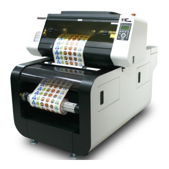
Chapter Mechanical Overview LABEL EXPRESS Overview DECAL EXPRESS Overview DECAL EXPRESS – ECO Version Overview Please take some time to familiarize yourself with this section regarding the mechanical www.GCCworld.com LABEL EXPRESS / DECAL EXPRESS User Manual... -
Page 26: Label Express Overview
LABELEXPRESS/DECALEXPRESS Series. References will be made back to the different parts of the LABELEXPRESS/DECALEXPRESS Series in later sections. LABEL EXPRESS Overview Emergency Stop 3.1.1 Front View Button Front Door Media Cover Air shaft (front) * Available in the model... -
Page 27: Top View
3.1.2 Top View Cover with Connection Port of Exhaust System Control Panel 3.1.3 Right (Profile) View SmartCONTROL Label CCD Connection Port USB Port Tool Storage * Available in the model with Auto feeding base www.GCCworld.com LABEL EXPRESS / DECAL EXPRESS User Manual... -
Page 28: Left (Profile) View
3.1.4 Left (Profile) View Machine Charging Port Compressor Charging Port Power On/ Off Switch Auto Feeder External I/O Port Roller Feeding On/ Off Switch Roller Charging Port ** Available to install external Auto Feeding Control www.GCCworld.com LABEL EXPRESS / DECAL EXPRESS User Manual... -
Page 29: Rear View
3.1.5 Rear View Ventilation Opening Waste Removal Module Air shaft (back)* * Available in the model with Auto feeding base www.GCCworld.com LABEL EXPRESS / DECAL EXPRESS User Manual... -
Page 30: Decal Express Overview
DECAL EXPRESS Overview Emergency Stop 3.2.1 Front View Button Front Cover Waste Drawer* (DL24 only) * See chapter 4.1.2 for details Media Cover Air shaft (front) * Available in the model with Auto feeding base WARNING Always keep the lock on both side of the front door locked. Visible and invisible laser radiation may be emitted from this aperture and hands may be injured by sharp objects or pinched by moving parts if the lock of front door is open. -
Page 31: Top View
3.2.2 Top View Cover with Connection Port of Exhaust System Control Panel 3.2.3 Right (Profile) View SmartCONTROL Decal CCD Connection Port USB Port Tool Storage * Available in the model with Auto feeding base www.GCCworld.com LABEL EXPRESS / DECAL EXPRESS User Manual... -
Page 32: Left (Profile) View
3.2.4 Left (Profile) View Machine Charging Port Compressor Charging Port Power On/ Off Switch Auto Feeder External I/O Port Roller Feeding On/ Off Switch Roller Charging Port ** Available to install external Auto Feeding Control www.GCCworld.com LABEL EXPRESS / DECAL EXPRESS User Manual... -
Page 33: Rear View
3.2.5 Rear View Ventilation Opening Waste Removal Module * Available in the model with Auto feeding base Air shaft (back)* www.GCCworld.com LABEL EXPRESS / DECAL EXPRESS User Manual... -
Page 34: Decal Express - Eco Version Overview
DECAL EXPRESS – ECO Version Overview 3.3.1 Front View Front Door Waste Drawer (DL24 only) Auto Feeder * See chapter 4.1.2 External I/O board for details Media Roller Media Basket (DL24-ECO only) 3.3.2 Side View Cover with Emergency Stop Connection Port of Button Exhaust System Control Panel... -
Page 35: Setup And Installation
Chapter Setup and Installation Machine Setup Software Setup www.GCCworld.com LABEL EXPRESS / DECAL EXPRESS User Manual... -
Page 36: Machine Setup (For Label Express & Decal Express )
Machine Setup (for LABEL EXPRESS & DECAL EXPRESS ) 4.1.1 Roll Media Installation Installation of airshaft and waste removal module Step 1 Insert the airshaft into the media core and expand it to firmly grab the media. Step 2 Secure the airshaft with media on the front side of the machine. www.GCCworld.com LABEL EXPRESS / DECAL EXPRESS User Manual... - Page 37 Step 3 Do the same to assemble another airshaft and install it to the machine on the rear side. Step 4 Put the media core to waste removal module and use the knob to secure the media core in place. www.GCCworld.com LABEL EXPRESS / DECAL EXPRESS User Manual...
- Page 38 Installation of roll media Step 1 Pull up the lever to release the front pinch rollers. Step 2 Pull up the lever on the back side of machine to release pinch rollers on the work area. Step 3 Pull the media pass through the front pinch rollers. www.GCCworld.com LABEL EXPRESS / DECAL EXPRESS User Manual...
- Page 39 Step 4 Pull the media beneath the front media shaft. Step 5 Load the media to pass through the work area. Tips: Make sure the media edge aligns with the paper stoppers. www.GCCworld.com LABEL EXPRESS / DECAL EXPRESS User Manual...
- Page 40 Step 6 Pull the media cross the first back media shaft and insert the media through the black panel. The first media shaft The media has to go through this back panel. The second media shaft Step 7 Pull the media out to go through between the second media shaft & the tension bar as below picture.
- Page 41 Step 8 Pull the media beneath the aluminum panel of the waste separation shaft. The aluminum panel of the waste separation shaft. Step 9 Pull the media beneath the third media shaft and over the forth media shaft. The third media shaft The forth media shaft Step 10 Pull the media through the waste separation shaft.
- Page 42 Step 11 Align the adjustable paper block with the media edge and fix it. The adjustable paper block Step 12 Separate the media. www.GCCworld.com LABEL EXPRESS / DECAL EXPRESS User Manual...
- Page 43 Step 13 Adhere the media to the paper core on the waste removal module. Tips: Stick the waste paper core with paper to remove the waste easily. Step 14 Pull the backing paper beneath the third media shaft. www.GCCworld.com LABEL EXPRESS / DECAL EXPRESS User Manual...
- Page 44 Step 15 And pull over the backing paper over the forth media shaft. Here is the alignment line on the shift Step 16 After alignment, adhere the backing paper to the paper core. Note: Make sure the backing paper is pulled taut in order to keep the paper tension before adhering to paper core.
- Page 45 Step 17 Align the adjustable paper block with the media edge and fix it. Step 18 Put down the lever to lower the front pinch rollers and the pinch rollers on the platen. www.GCCworld.com LABEL EXPRESS / DECAL EXPRESS User Manual...
- Page 46 Make sure the protrusion on the media clamp is wedged in the groove on the platen. Step 20 Turn on the roll system of LabelExpress and put down the lever to lower the front pinch rollers.
- Page 47 Step 21 Select “Auto feed” on the control panel to feed the media and then attach the rear media clamps (left and right) to align with the edge of the media. Step 22 Place the gravity bar onto the media to keep the paper tension while moving the media.
-
Page 48: Media Support Bracket Of The Waste Drawer (Decal Express Only)
4.1.2 Media Support Bracket of the Waste Drawer (DECAL EXPRESS only) The Waste drawer is a recessed container attached onto the work platform, which is used to collect unnecessary materials when performing cut through function. Media Support Brackets hold the media and keep the media flat while moving back and forth. Waste Drawer Media Support Bracket... - Page 49 Make sure media support brackets are secured in proper position and the DECAL EXPRESS is ready to work. NOTE The media support bracket is fixed by the magnet underneath; users can move the bracket to suitable position whenever needed. www.GCCworld.com LABEL EXPRESS / DECAL EXPRESS User Manual...
-
Page 50: Powering Up The Machine
Powering Up the Machine CAUTION Make sure both the LABELEXPRESS/DECALEXPRESS and the computer are turned off before connecting either to a power source. 1) Connect the male end of the power cord to a quality surge protector and then connect the surge protector to a properly grounded outlet. -
Page 51: Installation For Loading Roll Media
3) Connect another USB cable between computer and the SmartVISION Label CCD connection port 4) Turn on the master power on the left side of the LABELEXPRESS/DECALEXPRESS. Installation for loading roll media (for DECAL EXPRESS – ECO version) 4.1.5 www.GCCworld.com... - Page 52 1) Prepare the cut media: please note to roll media inside out as below picture. 2) Take out the wheel which is included in your package. 3) Install the wheel to the core. 4) Then place the whole roll on the machine. 5) Tight up the knob from the roll which is on the machine.
-
Page 53: Instruction Of Damper Roller
6) The installation of roll media is completed. 4.1.6 Instruction of Damper Roller www.GCCworld.com LABEL EXPRESS / DECAL EXPRESS User Manual... -
Page 54: Software Setup
Turn the wheel as instructed below to adjust damping. The bigger the number is, the stronger the damping. The volume symbol sticker indicates the damping level (Figure 2.3-6, 2.3-7). Figure 2.3-6 Figure 2.3-7 Software Setup www.GCCworld.com LABEL EXPRESS / DECAL EXPRESS User Manual... -
Page 55: Recommended Computer Configuration
4.2.1 Recommended Computer Configuration The LABELEXPRESS/DECALEXPRESS is able to accommodate Laptop and compatible PC operating systems. Both the machine and SmartCONTROL Label software were designed to work best using a Windows based system with the following minimum requirements. Intel Pentium, 1GHz or above... - Page 56 4) The installation would be finished in few seconds www.GCCworld.com LABEL EXPRESS / DECAL EXPRESS User Manual...
-
Page 57: Smartcontrol
5) When installation is complete, SmartCONTROL Label will create a “SmartCONTROL_LL” folder on windows desktop, open the folder and double click SmartCONTRL.exe to run the program. 4.2.3 SmartCONTROL Label Uninstallation 1) Open the SmartCONTROL_LL folder from windows desktop and double click “SmartCONTROL_Uninstall.exe”... - Page 58 3) The uninstallation would be finished in few seconds. 4) Uninstall Driver Package window will pop up and ask you “All devices using this driver will be removed. Do you wish to continue?” Click “Yes” to complete uninstallation. www.GCCworld.com LABEL EXPRESS / DECAL EXPRESS User Manual...
-
Page 59: Operating The Labelexpress/Decalexpress
Chapter Operating the LABELEXPRESS/DECALEX PRESS Using the Hardware www.GCCworld.com LABEL EXPRESS / DECAL EXPRESS User Manual... -
Page 60: Using The Hardware
5.1.1 Control Panel Overview The Control Panel The control panel on the LABELEXPRESS/DECALEXPRESS Series provides an easy access to all the manual controls needed for cutting. The liquid crystal display (LCD), functional, directional and selection buttons make navigating through the machine’s manual controls easy to do. - Page 61 Three indicator lights on the LABELEXPRESS/DECALEXPRESS control panel are part of the system’s safety interlock system. ‧ Power - The power light will illuminate when the LABELEXPRESS/DECALEXPRESS is powered on. ‧ Door - The door light will illuminate when the front door is open or improperly closed.
- Page 62 Function (F1 / F2 / F3 / F4) – Four function buttons allow you to select various functions which will change depending on what section of the menu you are in. Each function button’s corresponding task will be displayed right above its respective button on the LCD display screen.
-
Page 63: Graphic Control Panel Navigation Chart
5.1.2 Graphic Control Panel Navigation Chart 5.1.3 Graphic Control Panel Function Pages When the LABELEXPRESS/DECALEXPRESS is powered on, the machine will perform a series of safety checks and initialization routines. The LCD display screen will display the GCC copyright, GCC logo, and machine initialization pages before going to the main work page. - Page 64 Main Work Page The main work page is the page that the LABELEXPRESS/DECALEXPRESS will default to upon startup and will be the “home base” for when navigating through the various functions of the control panel. This will be the page that is displayed when you are processing your jobs.
- Page 65 Carriage Adjustment Page Navigating to this page: Main Work Page press, , or F3 Carriage Adjustment Page The Carriage Adjustment Page allows you to manually adjust the X-axis of the lens carriage and roll/unroll the media in Y-axis. Carriage / Work Table Adjustment Page Relevant Buttons Function...
- Page 66 Functions Page File Management Page – this page allows you to manage the files that you have loaded onto the LABELEXPRESS/DECALEXPRESS. Machine Setting Page – this page allows you to access and modify various machine settings, including: Set Red Beam, Set Command Mode, Set File Save Mode, Set Standby Mode, Set Vector Mode, Set Scaling, Set Auto-Feed, Set Save Position, Other, Reset.
- Page 67 Machine Setting Page Navigating to this page: Main Work Page press F4 Functions Page Select<Machine Setting>from the menu Machine Setting Page The Machine Setting Page allows you to access and modify various machine settings, including: Set Red Beam, Set Command Mode, Set File Save Mode, Set Standby Mode, Set Vector Mode, Set Scaling, Set Auto-Feed, Set Save Position, Other and Reset..
- Page 68 Machine Setting- Set Red Beam Page Navigating to this page: Main Work Page press F4 Functions Page Select<Machine Setting>from the menu Machine Setting Page Select<Set Red Beam >from the menu Set Red Beam Page The Set Red Beam Page allows you to turn on or off the red dot laser pointer on the lens carriage.
- Page 69 Machine Setting- Command Mode Page Navigating to this page: Main Work Page press F4 Functions Page Select<Machine Setting>from the menu Machine Setting Page Select<Set Command Mode>from the menu Set Command ModePage The Command Mode Page allows you to configure vector settings when outputting in Default or HPGL mode.
- Page 70 Setting File Save to <NO> will automatically and immediately delete each job file from the LABELEXPRESS/DECALEXPRESS Series after the cutting process. Setting File Save to <YES> will retain the job files on the LABELEXPRESS/DECALEXPRESS Series. • File Save: YES / NO...
- Page 71 Machine Setting- Standby Mode Page Navigating to this page: Main Work Page press F4 Functions Page Select<Machine Setting>from the menu Machine Setting Page Select<Set Standby Mode > from the menu Standby Mode Page The Set Standby Mode page allows you to configure the laser machine automatically enter into power saving if machine is idle for a specified time.
- Page 72 Machine Setting- Vector Mode Page Navigating to this page: Main Work Page press F4 Functions Page Select<Machine Setting>from the menu Machine Setting Page Select<Vector M ode > from the menu Vector Mode Page The Accel. (Acceleration) function modifies the acceleration and deceleration of the X and Y rails to adjust and balance vector mode’s quality and speed settings based on your specific job.
- Page 73 Machine Setting- Scaling Page Navigating to this page: Main Work Page press F4 Functions Page Select<Machine Setting>from the menu Machine Setting Page Select<Scaling> from the menu Scaling Page The Scaling Page allows you to fine tune the laser machine output scale to precisely fit the original graphic file design scale when precision output is requried to your application.
- Page 74 Machine Setting- Auto-Feed Page Navigating to this page: Main Work Page press F4 Functions Page Select< Machine Settings>from the menu Machine Settings Page Select<Auto-Feed> from the menu Select<SmartGUARD> Auto-Feed Page from the menu Select<SmartGUARD> from the menu Enable the Auto-Feed function allows you to activate the ultrasonic sensor, which can automatically feed the media to ensure a fluent workflow.
- Page 75 Machine Setting- Save Position Page Navigating to this page: Main Work Page press F4 Functions Page Select<Machine Setting>from the menu Machine Setting Page Select<Save Position>from the menu Select<Set File Save Mode >from the menu Save Position Page The Save Position Function allows you to save the current X-axis and Y-axis positions of the lens carriage to be the origin for subsequent jobs.
- Page 76 Machine Setting- Others Page Navigating to this page: Main Work Page press F4 Functions Page Select<Machine Setting>from the menu Machine Setting Page Select<Others> from the menu Others Page The Others Page allows you to change various settings that correspond to the control panel. The Language setting will allow users to change available languages displayed on the control panel.
- Page 77 Machine Setting- Reset Page Navigating to this page: Main Work Page press F4 Functions Page Select<Machine Setting>from the menu Machine Setting Page Select<Others> from the menu Others Page The Reset Page allows you to reset all changes made to the LaserPro Spirit Series Machine Settings Page to their default settings.
-
Page 78: Smartcontrol
SmartCONTROL Introduction 5.2.1 Reminder Window In order to avoid transmission collisions, each time you launch the SmartCONTROL software, it will show a reminding message that shut down SmartCONTROL first if you want to print files through other graphic software to laser machine. Click “OK” to open SmartCONTROL software. -
Page 79: Main Window
5.2.3 Main Window The Main Window of SmartCONTROL software is divided into several unique sections: The Menu Bar, the Tool Box, the Work Area, and the Property Table. Menu Bar Tool Box Property Table Work area Object Browser www.GCCworld.com LABEL EXPRESS / DECAL EXPRESS User Manual... - Page 80 Menu Bar Similar to many Windows based program, the Menu Bar contains the locations of almost all the functions of the SmartCONTROL Software. They are sorted into the following categories: File Menu Output Menu Edit Menu Draw Menu ...
-
Page 81: Processed Condition Setup
the object and press the right mouse button to choose Property Table. NOTE After you have edited one of the parameters in the Property Table, click on Apply or Apply to All in order to insert your changes. Object Browser The Object Browser would show a OBJECT BROWSER Window in the left side, and list all the objects you create on the working area, you can identify the object format, create sequence, name the object and select objects by clicking it in the OBJECT BROWSER... - Page 82 Pen parameters SmartCONTROL provides 16 color pens, and each pen presents laser parameter setting, once colors are set, the pen would refer to the specified parameters when you apply the colors to an output. Pen Parameters under Processed Condition Setup would enable you to adjust the power, speed of each color pen.
- Page 83 the perforation in the paper between mailing stamps). 4. Bridge Checking the Bridge Cutting checkbox will allow users to easily create perforation lines (dash-line). Once see the line color along with another corresponding pen can be used in tandem to indicate the length of the gap and the uncut part of a perforation line. (If Pen 1 is selected for bridge cutting, Pen 9 will be reserved to the length of the connected lines of the perforation.
- Page 84 Black & White mode Select this mode when using clipart images or drawings with several colors, shades of gray, or many outlines. This mode outputs in a method similar to that of a black and white laser printer. The GCC laser machine will interpret colored and shaded areas as 256-level shades of gray by producing a halftone effect while engraving.
-
Page 85: Output
will start a job from this home position and return to the home position after completed jobs. (3) SmartCONTROL Label More detailed setting can be found in Chapter 5.3. 5.2.5 Output The output box would show all the output setting, and you can press Execute to start cutting or press Exit to close output and return to editing or output setting. -
Page 86: Smartcontrol
SmartCONTROL Software Label Function 5.3.1 Running the SmartCONTROL software program and click “New File” or “Open File” to open (1) Launch SmartCONTROL history file. (2) Go to “Vision” in the Menu Bar and select “SmartCONTROL Label”. (3) Make sure connection status indicator shows green for both “USB” and “CCD” Status. www.GCCworld.com LABEL EXPRESS / DECAL EXPRESS User Manual... - Page 87 NOTE If the connection status indicator shows red, please reconnect the two USB cables and make sure “USB Status” green light is on, and the “CCD Status” green light is blinking. ▲Incorrect Connection ▲ Successful Connection Incorrect connection may cause the SmartVISION Label fail to work.
-
Page 88: Tm Label Main Window
5.3.2 SmartCONTROL Label Main Window Laser ROI Frame SmartCONTROL Label (Blue Frame) Function Live View Window Connection status indicator signs Arrow Keys for CCD module Learned Mark Window SmartCONTROL Label Function There are two functions of SmartCONTROL Label, including Calibration and Operation. ... -
Page 89: Tm Label Function
Arrow Keys for CCD module To fine tune the position of the SmartVISION Pro CCD module Stop SmartCONTROL Label Stop the operation of SmartCONTROL Label 5.3.3 SmartCONTROL Label Function The SmartCONTROL Label function is divided into two unique sections: the Calibration and the Operation. - Page 90 NOTE If the actual cutting contour line is on the left of printed graphics by 5 mm and 3 mm below the printed graphics, enter “-5” in X and “3” in Y in Laser Offset section for laser offset calibration. Actual cutting contour line The contour of printed graphics - Print Offset...
- Page 91 CCD Adjust Distance Move the position of the CCD module rightwards or leftwards to allow CCD module to read the registration mark when the mark is out of field of view of the CCD module. If moving CCD module rightwards, input positive value and input negative value if moving leftwards.
- Page 92 Mark Learning - Mark Mode Define using two-mark mode. - Mark Number Assign a number to the mark SmartCONTROL Label is about to learn. - Start Learning Start to lean the marks. Select 1st mark to start learning, and the 2nd mark learning will be succeeded automatically after 1st mark learning is complete.
-
Page 93: Calibrating Smartcontrol
Calibration function is to calibrate the shift and angle variation caused by printing or media loading. Perform the calibration to ensure the cutting accuracy. 1) Load the printed roll media onto LABELEXPRESS/DECALEXPRESS. 2) Launch SmartCONTROL and Click "Vision" on the menu and select “SmartCONTROL Label”... - Page 94 4) Click the “Start” button in “Calibration” tab. 5) The laser machine will engrave a calibration mark. www.GCCworld.com LABEL EXPRESS / DECAL EXPRESS User Manual...
- Page 95 6) Move the CCD to the position where the screen shows the engraved calibration mark and make sure the frame crosshair is aimed at the center of the mark. Users can use the Arrows Key to fine-tune the position of ROI frame. 7) Click Calibration button to complete the CCD calibration.
-
Page 96: Convert And Import File
5.3.5 Convert and Import File For the best output quality, we recommend you convert the graphic file to prn format via SmartCONTROL print driver from the graphics software (e.g. CorelDRAW or Illustrator). SmartCONTROL print driver will install to your computer automatically when you installed SmartCONTROL software. - Page 97 From the navigation bar on the left, click Document → Page → Size. Ensure that LANDSCAPE is selected. Input the size of Width and Height dimensions to match the LABELEXPRESS/DECALEXPRESS work area dimensions. LABELEXPRESS/DECALEXPRESS with SmartVISION Pro CCD: 381mm x 500mm (15”...
- Page 98 Set page size to fit SmartVISION Pro CCD working area from graphics software. Click OK to end the paper size adjustment. Here we use CorelDraw as illustration of how to convert a file. Select all the designed objects and set the outline to hairline from tool bar in the graphics software.
- Page 99 Select “SmartControl Label” to output. If you do not find “SmartControl Label” from the printer list, please check if SmartControl is properly installed in your computer. www.GCCworld.com LABEL EXPRESS / DECAL EXPRESS User Manual...
- Page 100 Click “Color” tab to make sure the “Output colors as:” set as RGB, and then click “OK” to continue. Click “OK” and Print To File window will appear www.GCCworld.com LABEL EXPRESS / DECAL EXPRESS User Manual...
- Page 101 Select the save folder, define file name and select file type as prn, then click “Save” to convert Close the graphics software (here is Corel Draw) and open the SmartCONTROL Software. Click “File” “Import” Select the converted file and click “Open” to import the saved file to SmartCONTROL www.GCCworld.com LABEL EXPRESS / DECAL EXPRESS User Manual...
- Page 102 10) File import is completed. www.GCCworld.com LABEL EXPRESS / DECAL EXPRESS User Manual...
-
Page 103: Operating Smartcontrol
5.3.6 Operating SmartCONTROL Label It is suggested to use square as registration mark to ensure high precise cutting. NOTE The recommended value for registration mark size is 3 mm. SmartCONTROL will automatically define the mark #2. Make sure all the registration marks are the same type and filled before converting the graphic file to prn format. - Page 104 Perform roll media cutting Load the printed roll media on the work area. Open the file or import prn file illustrated in Chapter 5.3.5. Select the square on the upper left side of the graphic and select Mark1 Definition under Vision menu to define it as the first mark.
- Page 105 Select the square on the lower left side of the graphic and select Mark2 Definition under Vision menu to define it as the second mark. NOTE If you want to redefine the mark1 and mark2, select Clear Mark Def under Vision menu and repeat the above steps to redefine the marks.
- Page 106 Go to the “Operation” tab, the default setting of Mark Mode is 2 Marks. Input registration mark Diameter/Length value in the Mark Diameter /Length field. Move the media forward/backward to allow SmartVISION Pro CCD module to read the first mark and show the mark on the software screen. Use the mouse to move the laser ROI frame until the crosshair of the frame aims at the center of registration mark.
- Page 107 Users can use the Arrows Key to fine-tune the position of ROI frame. www.GCCworld.com LABEL EXPRESS / DECAL EXPRESS User Manual...
- Page 108 Click ”Start Learning” button, the Learned Mark Window will show the memorized pattern and the mark 1 and mark 2 will be learned successively. Mark Learned Window 10) Define the number of rows will be cut each job and the times the laser system to output the same job.
- Page 109 11) Click "Output" on menu bar and click "Processed Condition Setup" 12) Select machine from “Machine Mode” and set the processing parameter in “Pen Parameter” tab. 13) Select the objects to be cut. www.GCCworld.com LABEL EXPRESS / DECAL EXPRESS User Manual...
- Page 110 14) Click "Output" on menu bar and click "Output". 15) Check "Output Selected Objects Only" and the "Execute" button to start CCD reading and laser processing. NOTE If there is any emergency when SmartCONTROL Label is processing, press "STOP SmartCONTROL Label" button to stop the CCD action immediately. www.GCCworld.com LABEL EXPRESS / DECAL EXPRESS User Manual...
-
Page 111: Ccd Light Adjustment
16) SmartVISION Pro CCD will automatically search for the registration marks and perform laser cutting jobs. 5.3.7 CCD Light Adjustment 1) Go to Vision and click “SmartCONTROL Label&Decal” 2) Choose Operation Function www.GCCworld.com LABEL EXPRESS / DECAL EXPRESS User Manual... - Page 112 3) There is a CCD Light which you can adjust the lightness from 0 to100 0: CCD Light off 100: CCD Light on www.GCCworld.com LABEL EXPRESS / DECAL EXPRESS User Manual...
-
Page 113: Labelexpress / Decalexpress Sample Book Suggested Parameters107
5.3.8 LabelExpress / DecalExpress Sample Book Suggested Parameters GCC LabelExpress/DecalExpress delicate sample book is now available for purchasing. Follow the below steps, you will find GCC suggested parameters for those materials shown in the sample book. 1) Go to Help and click “About SmartCONTROL…”... - Page 114 3) Then you will see GCC suggested parameters for LabelExpress/DecalExpress (30W) shown in the list. NOTE Parameters are subject to change on laser wattage and material dependent. www.GCCworld.com LABEL EXPRESS / DECAL EXPRESS User Manual...
-
Page 115: Chapter 6 Basic Maintenance
Chapter Basic Maintenance Suggested Cleaning and Maintenance Supplies Maintaining the Work Table and Motion System - Cleaning the Work Area and Motion System - Lubrication of the X Rails www.GCCworld.com LABEL EXPRESS / DECAL EXPRESS User Manual... -
Page 116: Suggested Cleaning And Maintenance Supplies
Keeping your LABELEXPRESS/DECALEXPRESS Series clean and well maintained will ensure quality output, consistent reliability and extended product life. Smoke, dust or residue build-up inside the laser system or the mechanical components can cause a reduction in the laser power, irregularities in the motion system, reduced product life cycle, and a host of other avoidable problems. -
Page 117: Maintaining The Work Area And Motion System
Clean the working area and the motion system on a frequent basis through the following steps: Turn the power off and unplug the LABELEXPRESS/DECALEXPRESS before cleaning. Use a vacuum cleaner with a flexible nozzle to remove dust and debris from the work area and motion system. -
Page 118: Cleaning The Grid Drum
CAUTION Never pour or spray alcohol or acetone directly to the work table. Oil, alcohol and acetone can cause fires or smoke build-up if improperly used. 6.2.2 Cleaning the Grid Drum 1. Turn off the machine, and move the tool carriage away from the area needed to be cleaned. -
Page 119: Cleaning The Clamps And Waste Separation Bar
6.2.4 Cleaning the Clamps and Waste Separation Bar Sticky residues and dust may be generated during operation and left on the clamps on the work area or the waste separation bar on the back side. Use a lint-free cloth or cotton swab to wipe away the accumulated residues and dust. -
Page 120: Cleaning The Mirrors
6.3.2 Cleaning the Mirrors After removing the mirror, you will want to inspect each mirror for scratches, smoke residue, or debris. If any residue or debris is present, use the following steps to clean the mirrors. 1) Hold the mirror with the reflective side up, without touching the reflective side of the mirror (DO NOT apply any finger pressure or any other cleaning solutions to the mirror surface). -
Page 121: Removing And Cleaning The Focal Lens
6.3.3 Removing and Cleaning the Focal Lens Unscrew the three thumbscrews securing the lens carriage panel and remove the lens carriage panel to reveal the focal lens. Carefully pull out the focal lens. Clean the focal lens with a cotton swab and lens cleaner solution. Be sure to clean both sides of the focal lens (DO NOT apply any finger pressure or other cleaning solutions to the lens surface). -
Page 122: Chapter 7 Appendix
Chapter Appendix GCC LABELEXPRESS/DECALEXPRESS Specification Sheet www.GCCworld.com LABEL EXPRESS / DECAL EXPRESS User Manual... - Page 123 GCC LABEL EXPRESS Specification Sheet Model LABEL EXPRESS Model Number LE15-20V93 LE15-30V LE15-25Vi102 Cutting Width 381 mm (15") 381 x 330 mm (15” x 13”) Work Area (Sheet) (W x L) Width 85 mm to 400 mm (3.4” to 15.7") Max.
- Page 124 Machine 1,070 x 1,441 x 1,180 mm (42.2 x 53.2 x 46.7 in.) Dimensions (W x L x H) Shipping 1,320 x 1,660 x 1,490 mm (52 x 65.4 x 58.7 in.) Machine 250 kg Weight Shipping 385 kg Facility Requirement Electrical 100~240 Volt AC, 50/ 60Hz, Auto Switching, Max.
- Page 125 Maximum Speed 1,530 mm/s (60ips) (for straight line cutting) Adjustable from 0.1~100% (Up to 16 color-linked speed settings per Speed Control job) Adjustable from 0~100% (Up to 16 color-linked speed settings per job) Power Control Alignment System CCD Module Distance Accuracy 0.254 mm or 0.1% of move, whichever is greater Computer interface Standard USB port...
- Page 126 Available in the model with Auto-feeding base * Please visit GCC club for the latest user manual download. GCC reserve the right to modify the user manual without notice. www.GCCworld.com LABEL EXPRESS / DECAL EXPRESS User Manual...
Need help?
Do you have a question about the LabelExpress and is the answer not in the manual?
Questions and answers