Table of Contents
Advertisement
Quick Links
Advertisement
Table of Contents

Related Manuals for GCC Technologies AFR-24S


Summary of Contents for GCC Technologies AFR-24S
- Page 1 AFR-24S User Manual http://www.GCCworld.com V.2 2020 Oct.
- Page 2 AFR-24S User Manual NOTICE GCC reserves the right to modify the information contained in this user manual at any time without prior notice; un-authorized modification, copying distribution or display is prohibited. All comments, queries or suggestions concerning this manual please...
-
Page 3: Table Of Contents
AFR-24S User Manual Safety Measures Necessary work space 1. General Information Introduction Package Items Machine Overview 1.3.1 AFR-24S Overview 1.3.2 Cutter Overview 1.3.3 Appearance of RX II 1.3.4 Pinch Roller 2. Installation Connecting Your GCC Cutter 2.1.1 USB Connection 2.1.1.1 Driver Installation 2.1.1.2 Driver Un-installation... - Page 4 AFR-24S User Manual 4.1.1 Automatic Working Procedure 4.1.2 Back Creasing How To Load The Sheet Media Into Machine Without Auto Feeder Cutting Force And Offset Adjustment How To Cut 3mm Letter When Completing The Cutting Job RX II-Creasing Print Driver Setting 4.6.1 RXII-Creasing Print Driver setting >...
-
Page 5: Safety Measures
AFR-24S User Manual Safety Measures Before you start installation, please read below information carefully to avoid potentially hazardous situations. General safety Use the voltage of the power source is identical to the voltage of the machine to prevent any damage or failure. - Page 6 AFR-24S User Manual 【Important Information】 For safety concern, please always hold the cutter firmly from the bottom while moving it. Do not move the cutter by clasping the depression area on both sides. O (Correct) X (Incorrect) Hold from the bottom Hold the depression area ...
- Page 7 AFR-24S User Manual Warning Never press the top release grip and pull the bottom release grip at the same time as the pictures shown below: O (CORRECT) X (INCORRECT) Press down Press down DISABLE Stop bar Note: In case the grips clipped together...
-
Page 8: Necessary Work Space
AFR-24S User Manual Necessary work space Prepare a working table that accommodates your RXII-61 with auto feeder. The required working table should be larger than 1,100 mm in width, 800 mm in length and 600 mm in height. Prepare three outlets for your RXII, auto feeder and your computer. -
Page 9: General Information
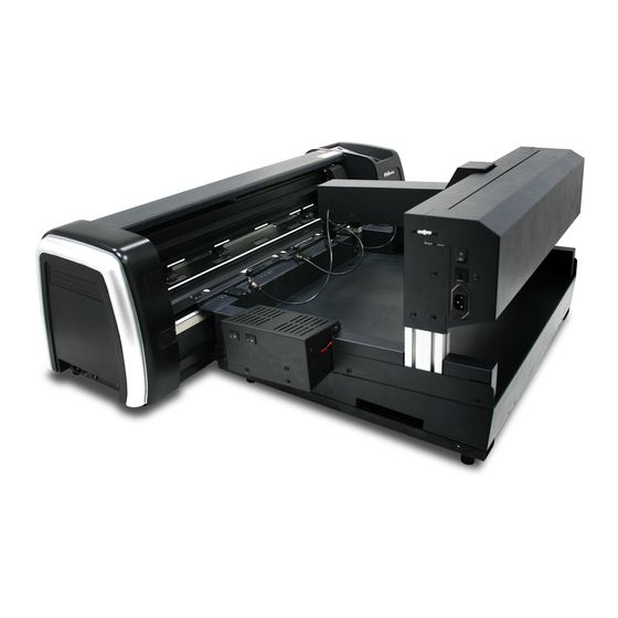
Chapter 1 General Information Introduction In combination of a cutter and an auto sheet feeder, AFR-24S provides the advantage of creasing function with dual tool holder up to 600gsm cutting force and 1,530 mm/s cutting speed in the digital sheet feed solution that can crease and cut at one time sheet by sheet... - Page 10 AFR-24S User Manual Auto Feeder Package Q’ty Item Photo Auto Feeder 1 unit Auto Feeder Accessories Media collection tray 1 set Left & Right 2 pcs connecting bracket Thumb screw 2 pcs Screw 4 pcs Power cable 1 pc RS232 cable...
-
Page 11: Machine Overview
AFR-24S User Manual Machine overview 1.3.1 AFR-24S overview Blower Media block Magnetic media separator Serial interface connector (RS232C) Suction cup Media storage tray Item Function Serial Interface Used to connect a feeder to a cutter through a serial Connector interface (RS232) cable... - Page 12 AFR-24S User Manual Power switch Power port Media collection tray Stretchable stand Item Function Power port A socket for power cable. Power switch Switch the Auto feeder on and off. Adjustable media Collect the cut media after completing the job...
-
Page 13: Cutter Overview
AFR-24S User Manual 1.3.2 Cutter overview Power Port Fuse Power Switch Item Function Power Switch On when switches to [I]; Off to [O] Fuse 3 Amp Power Port A socket for AC power cable. USB Connector Ethernet Connector Serial Interface... -
Page 14: Appearance Of Rx
AFR-24S User Manual 1.3.3 Appearance of RX II Grid Drums move – the media back and Tool Carriage performs the – forth during operation. cutting with the installed blade and pen with AAS module. Platen provides the – surface for holding and... -
Page 15: Pinch Roller
AFR-24S User Manual 1.3.4 Pinch roller The Multi-Pressure Pinch Rollers give users three pressure settings to better cater to the different types of media that they are working with, for example, set light hold-down pressure of the pinch roller in the middle when cutting thin materials such as window tinting film. -
Page 16: Installation
AFR-24S User Manual Chapter 2 Installation GCC AFR-24S provides two mode selections and can be used it separately as either a regular plotter (RXII-61 Creasing) or assembling with feeder (AFR) to process media sheets cutting. The following instruction will lead you how to install and operate in the regular plotter (RXII-61 Creasing) and AFR separately. - Page 17 AFR-24S User Manual Step 1 Put the installation DVD into your CD-ROM. Please make sure that the USB device is connected before you start the driver installation. Step 2 Choose the model you want to install from the driver list and click on Windows...
- Page 18 AFR-24S User Manual Step 5 Please make sure the cutting plotter is powered on and connected to the USB device, and then click OK to next step. Step 6 Confirm to close all running application programs before you start installing the driver, and then click OK.
- Page 19 AFR-24S User Manual Step 9 Check Install Message to confirm CorelDRAW and AI version and then click OK. Note: (1) If the driver is being installed for a second time, the user will be prompted as to whether a second copy of the driver installation is required.
-
Page 20: Driver Un-Installation
AFR-24S User Manual version of GCC AAS Plug-in. 2.1.1.2 Driver Un-installation You have to remove previous version driver installed on your PC system completely before you can install the latest version successfully. Please refer to below steps. Step 1 Go to Control Panel\Hardware and Sound\Devices and Printers window. Right click... - Page 21 AFR-24S User Manual After removing the unit, click on any printer on the page and select “Print server Step 2 properties.” (For Win 7 and above) or right click on blank space and then select “Print server properties.” (For Windows XP) Select “Driver”...
- Page 22 AFR-24S User Manual Select the model and click on “Remove”. Step 4 Select “Remove driver and driver package” and click OK. Step 5 Click “Yes” and then click “Delete” and “OK,” and the driver installed on PC is Step 6...
-
Page 23: Connection
AFR-24S User Manual 2.1.2 RS-232 Connection Connecting to the RS-232 (Serial) Port 1. For IBM PC, PS/2 users or compatibles, connect the RS-232C cable to the serial connector of the assigned serial port (COM1 or COM2) of your host computer. - Page 24 AFR-24S User Manual Step 3 Go to the DHCP page and select Enable through the up and down arrow keys, then press Enter. Step 4 The IP Address will be shown on the screen automatically. Please make notes of it.
- Page 25 AFR-24S User Manual Step 2 Go to Output Devices under Settings. Step 3 Select a model at Driver in Setup Device window Step 4 Input the IP address you had acquired from the control panel to the TCP/IP. Click OK...
- Page 26 AFR-24S User Manual Step 5 Go to Output under File to check the settings. Complete the driver installation process and your GCC Cutting Plotter is now allowed to network. Note: If you want to add new local device, please go to Output Devices under Settings, and...
-
Page 27: Data Transmitting
AFR-24S User Manual II. Output through Ethernet Driver Step 1 Connect Ethernet cable to PC and install Cutter Ethernet driver. Then click OK to continue. Step 2 Enter the IP Address shown on the control panel and select the model. (Please refer part 1 instruction.) -
Page 28: Printer Sever Shared Setting
AFR-24S User Manual 2.1.5 Printer Sever Shared Setting In “A-PC”, set the printer driver as a shared printer, then use B-PC to connect A-PC’s printer driver via Intranet. A-PC B-PC Intranet USB or COM Port Set A-PC’s printer driver as a shared printer (Right-click on printer icon, choose Step 1 “Printer properties”. - Page 29 AFR-24S User Manual Click “Advanced” tab, then choose “Print directly to the printer” option. Step 2 Step 3 Send a job from A-PC to the machine to check if A-PC is connected to the machine. Try to send a job to check if the port is working.
-
Page 30: Auto Feeder Installation
AFR-24S User Manual 2.2 Auto feeder installation 1. Assemble the right and left connecting brackets on both side of the auto feeder with screws to fix the auto feeder to cutter. 2. Tighten the thumb screw to fix the connecting brackets to the side plate of the cutter. - Page 31 AFR-24S User Manual 5. Loose the screw on the rear platen. 6. Fix the connecting bracket on the rear platen with screws. 7. Then assemble the media collection tray onto the connecting bracket.
- Page 32 AFR-24S User Manual 8. Make sure the stretchable stands on both side reach the ground and brace the media collection tray. 9. Inset the media stopper into the groove of the media collection tray. The media stopper is fixed by magnet, adjust the media stopper to proper position depending on the size of...
-
Page 33: Install The Magnetic Media Separator
AFR-24S User Manual 2.3 Install the magnetic media separator The function of a magnetic media separator is to prevent sheet media from double feeding while loading sheet media to a cutter. A magnetic media separator contains a magnet which is used to attach the media separator to a feeder. - Page 34 AFR-24S User Manual Adjustment depth knob Outward ring Step 1 Install blade. Step 2 Push the blade to the bottom of the blade holder. Adjust the blade tip to suitable length by screwing “Blade tip adjustment screw” Step 3 clockwise or count-clockwise.
-
Page 35: Blade Holder Installation
AFR-24S User Manual 2.4.2 Blade Holder Installation Step 1 Loosen thumb screw and insert the blade holder into extension holder Step 2 Fasten the thumb screw to fix the tool carriage. Step 3 The machine is ready to use. Step 4... -
Page 36: Automatic Blade Length Detection
AFR-24S User Manual Eject the blade. Push “Blade eject pin” to eject blade when the blade needs to be Step 5 replaced. Caution The blade will lose its sharpness after a period of usage; the cutting quality might be affected. - Page 37 AFR-24S User Manual 2. Align one of the scales on the blade holder to the mark on the carriage 3. Select “Blade Length Adjust” under “CUT TEST” on the LCM, and enter the blade length wished in “Set Length”; test the blade holder first and then test the blade length by pressing ENTER.
-
Page 38: Creasing Tool Installation
AFR-24S User Manual 2.6 Creasing Tool Installation Step 1 Remove the Creasing tool and holder from the carriage. Make sure the cylinder is at “UP” position Step 2 Press the cylinder by hand and hold the bottom to ensure the VCM to be hold while pressing as shown on below pictures. - Page 39 AFR-24S User Manual Step 4 Make sure the tool is insert to the bottom of the holder tube and turn the hand screw to lock it’s position Press down the tool tip to ensure the toll is set at the bottom of the holder...
- Page 40 AFR-24S User Manual Step 6 Press the top of the creasing tool and hold at bottom of the cylinder to ensure the holder is set at the proper high. Step 7 Turn the lower hand screw to lock the position of creasing toll and holder...
-
Page 41: Software Installation
AFR-24S User Manual 2.7 Software Installation 2.7.1 GreatCut Installation Step 1 Click GreatCut Registration in installation DVD to go to http://gccvoucher.eurosystems.lu/, and then enter your voucher code provided when purchasing GreatCut and click “Go on!” Click “Request” to go to registration page. - Page 42 AFR-24S User Manual Fill in the required information and click “Request license code.” Step 3 Step 4 The registration is completed; you should receive two emails, one is registration confirmation with activation link and another is your license data with .ecf...
- Page 43 AFR-24S User Manual //Or click “Install GreatCut” in installation DVD. Step 6 Step 7 Select a destination folder. Select “Typical” and click “Next”. Step 8 Note: You may select custom setup to install additional drivers.
- Page 44 AFR-24S User Manual Step 9 Select the folder and click Next. Default program folder in the start menu is GCC\GreatCut 3. Step 10 GreatCut is installing. Click “Finish” to complete installation. Step 11...
- Page 45 AFR-24S User Manual Step 12 Before you launch GreatCut, open the .ecf attached to the license data email to install your license data to GreatCut so that you don’t need to fill in your information again. Step 13 If the license do not install successfully, you will need to fill in your license data...
-
Page 46: Sure Cuts A Lot Installation
AFR-24S User Manual Step 14 GreatCut is ready to use now. 2.7.2 Sure Cuts A Lot Installation (Optional Item) 2.7.2.1 Auto Installation Step 1 Put your installation DVD into your CD-ROM to start the installation. The software is compatible with Windows 7 and above and Macintosh OSX 10.6 and above. - Page 47 AFR-24S User Manual Select “I accept the agreement” and press “Next.” Step 4 Step 5 Use the default folder (suggested) or select a folder you want to install the Sure Cuts A Lot and press “Next.”...
- Page 48 AFR-24S User Manual Tick “Create a desktop icon” if you want to create a shortcut on your desktop, and tick Step 6 “Associated scut4 extension” to associate the scut4 extension file with Sure Cuts A Lot software. Then press “Next” to start the installation.
- Page 49 AFR-24S User Manual Tick “Launch Sure Cuts A Lot,” and then press “Finish” to compete installation. Step 7 Step 8 Run Sure Cuts A Lot. Press “Activate…”to activate Sure Cuts A Lot. Please make sure it is connected to Step 9...
- Page 50 AFR-24S User Manual Step 10 Put your name in the Name column and enter the 25-letter software key shown on the DVD front cover to the Serial column and press “OK” to complete the activation. Launch Sure Cuts A Lot, select “My Cutter” under “Cutter” and select “Manage Step 11 Cutters.”...
-
Page 51: Manual Activate Software
AFR-24S User Manual Note If you use a trial version to output graphics, meaning you do not enter the software key to activate the Sure Cuts A Lot mentioned above, there will be two extra lines cut through the design, therefore, make sure the Sure Cuts A Lot software is activated before implementing cutting jobs. -
Page 52: Re-Install Sure Cuts A Lot Software
AFR-24S User Manual Step 4 Copy and paste the activation code back into the activation dialog box of Sure Cuts A Lot program and hit ok. 2.7.2.3 Re-install Sure Cuts A Lot Software If you change a new computer, you may need to deactivate your Sure Cuts A Lot software and re-install it on your new device. -
Page 53: Desktop Flexible Media Support System
AFR-24S User Manual 2.8 Desktop Flexible Media Support System (machine only) The following installation of desktop flexible media support system is only used in the machine individually without assembling with auto feeder. Step 1 Put the 4 Plastic Foot under the Roll Holder Support and insert the M4 screw into the hole of Plastic Foot and tighten them with the M4 L-shape screw driver. -
Page 54: Instruction Of Damper Roller
AFR-24S User Manual Step 4 Place the two roll holders into the holes of Roll Holder Support (Figure 2-16). Step 5 The complete Desktop Media Support System will be shown as in Figure 2-17. Figure 2-17 Instruction of Damper Roller (machine only) Turn the wheel as instructed below to adjust damping. -
Page 55: Replacing Cutoff Blade
AFR-24S User Manual 2.10 Replacing Cutoff Blade Step 1 Unscrew the Cover from the Tool Carriage using a screw driver (Figure 2-31 and 2-32). Figure 2-31 Figure 2-32 Step 2 Manually disassemble the Cover, which will still be connected to the Tool Carriage through wires (Figure 2-33 and 2-34). - Page 56 AFR-24S User Manual Step 3 Disconnect the black and red wires between the Cover and the Tool Carriage from the white Wire Joint and the Cover will be removed completely (Figure 2-35 and 2-36). Note: Please disconnect the wires at the white Wire Joint with care as the fans will not be working if these wires are split elsewhere.
- Page 57 AFR-24S User Manual Step 5 Remove the entire Cut-off Unit by holding it while pushing the tiny metal board on the right to the left (Figure 2-39 and 2-40). Push to the left Metal Board Figure 2-39 Figure 2-40 The Cut-off Unit will drop automatically once the board is pushed to the left (Figure 2-41).
- Page 58 AFR-24S User Manual Figure 2-43 Screw Figure 2-44 Step 7 Unscrew the Cut-off Blade from the Cut-off Blade Fixer, which will be attracted by the magnet on it, and replace it with a new Cut-off Blade along the track highlighted in red using tweezers (Figure 2-45 and 2-46).
- Page 59 AFR-24S User Manual Step 8 Assemble the Cut-off Blade Fixer back to the Cut-off Unit by pushing the Holder downwards (Figure 2-47 and 2-48) and attach the screw (Figure 2-49). Figure 2-47 Figure 2-48 Figure 2-49 Step 9 Assemble the Cut-off Unit back to the Tool Carriage by pushing the metal board on the right while pushing the Cut-off Unit upwards (Figure 2-50 and 2-51) and attaching the screw (Figure 2-52).
- Page 60 AFR-24S User Manual Push to the left Figure 2-50 Figure 2-51 Figure 2-52...
- Page 61 AFR-24S User Manual Step 10 Reconnect the wires at the white Wire Joint (Figure 2-53). Figure 2-53 Step 11 Assemble the Tool Carriage Cover back to the Tool Carriage; please locate the end of the screw to the hole on the carriage before tightening the screw (Figure 2-54).
-
Page 62: The Control Panel
AFR-24S User Manual Chapter 3 The Control Panel This chapter describes the button operations with the LCM menu flowcharts of RX II series. When the cutting plotter is ready for use as described in Chapter 1 & 2, all functions are under default parameters. - Page 63 AFR-24S User Manual CUT TEST To perform cutting test on different media. To cut off the material when the job is completed. CUT OFF MISC To set up functions. TOOL SELECT To select tools. DATA CLEAR To clear up internal memory.
-
Page 64: Menu In On-Line Mode
AFR-24S User Manual Menu in On-line Mode Power on When Setting Paper To Load: Place Media ** Please Don’t ** To Setup: Valid Keys *** TOUCH ANY KEY *** Roll Edge Single Press Function Key to select IF NEEDED Initializing RX When Media Is Detected Please Wait…... -
Page 65: Menu In Off-Line Mode
AFR-24S User Manual 3.3 Menu in Off-line Mode Offline For System Setup move origin M C Speed: 72 cm/s C Speed: 3~153 with an increment of 3 (cm/s) Select: OK:ENTER P Speed: 72 cm/s P Speed: 3~153 with an increment of 3 (cm/s) - Page 66 AFR-24S User Manual Offline For System Setup 1S:72 F:80 O:0.275 M Select from 1S to 4S Select: OK:ENTER Set Smoothing Cut Select: OK:ENTER OverCut: 0.00~1.00mm with an OverCut: 0.00mm increment of 0.05mm Select: OK:ENTER [ TOOL SELECT] Set Tangential Mode...
-
Page 67: Menu Items
AFR-24S User Manual Image Scale Length Select: OK:ENTER Image Scale Width Select: OK:ENTER [ MISC] Set communication Select: OK:ENTER DHCP Enabled, Disabled Select: OK:ENTER IP Address IP Address set, Submask set, Select: OK:ENTER Gateway set MAC Address 00:CF:52:72:03:01 English, Francais, Türkce, Polski, Ingles, Japanese,... - Page 68 AFR-24S User Manual --- POWER --- To indicate the power status. [ Arrow Keys ] 1. To move the tool carriage position on X or Y axis. 2. To select functions or change values of settings. [ ENTER ] 1. The displayed parameters will be saved automatically.
- Page 69 AFR-24S User Manual C Quality To set or modify cutting quality (acceleration). Draft, Fair, Normal Draft (4.2G), Fair (2.8G), Normal (1.4G), Fine (0.7G), Normal, Fine, Small Letter (0.2G). Small Letter While cutting small letter, set as “Small letter”. While cutting in high speed, set as “Draft”.
- Page 70 AFR-24S User Manual [ DATA CLEAR ] To clear up buffer memory. [ TOOL SELECT ] Save Parameter To save pattern(s) of cutting parameters for later use. Pattern 1: Patterns 3 There are 4 sets of parameters saved in the panel. Use vinyl &...
- Page 71 AFR-24S User Manual If the value of Adjust paper is bigger, the sheet media loaded to work area will be backward This setting only works when using cutter with auto feeder, or under single mode when using cutter alone. (*auto feeder is an optional...
- Page 72 AFR-24S User Manual want to plot, finishing settings press “Enter” key to next step. 2. If the pen and cutter lines are not matched, please refer to the table below for adjust X and Y values in “Pen overlap Cut”...
- Page 73 AFR-24S User Manual MAC Address Shows the MAC Address of your cutting plotter. Select To select displayed languages on LCM panel in English, English Language Spanish, Italian, Deutsch, Japanese, Portuguese, Polish, Turkish or French. Select Units Provide four-unit systems for users convenient.
-
Page 74: Operation
AFR-24S User Manual Chapter 4 Operation 4.1 How To Load The Sheet Media Into The Auto Feeder Step 1 Place the sheet media flat on the stack of the feeder and adjust the pinch roller to proper position according the media size. - Page 75 AFR-24S User Manual jAdjust the pinch roller to proper position according to the media size. The Step 3 alignment label provides a quick view of the suggested position of pinch rollers for different media sizes. Step 4 Use a RS232 cable to connect the feeder and cutter.
- Page 76 AFR-24S User Manual Step 7 Lower down the lever to raise the pinch roller. Press “ENTER” key to start media width sizing. Step 8 Go to “MISC” menu, use arrow left/right keys to select “Adjust Paper” and press Step 9 “ENTER”...
- Page 77 AFR-24S User Manual Note: “ Adjust paper” is to calibrate position of media front edge after sizing. If the value of Adjust paper is bigger, the distance of the media front edge will be closer to cutting blade. Use arrow left/right keys to select “AAS copy” and press “ENTER” key .
-
Page 78: Automatic Working Procedure
AFR-24S User Manual 4.1.1 Automatic Working Procedure 1. Pick up the media from tray to load it into the cutter NOTE: Blowers installed on both side of media tray will automatic turn on while the media is ready to be picked up to separate the media. You can control the air volume by turning off the fans according to the media type. - Page 79 AFR-24S User Manual 3. Start the creasing job NOTE: Only available while you set the creasing function in software (Please refer to 4.6.2 RX II-Creasing Print Driver setting > Creasing Page) ) 4. After completing the creasing, it will come to cut directly.
-
Page 80: Back Creasing
AFR-24S User Manual 4.1.2 Back Creasing In order to prevent the printed image scratching during creasing process, creasing and cutting from the back of printed paperboard is the best solution that can keep the printed image in a perfect condition. -
Page 81: How To Load The Sheet Media Into Machine Without Auto Feeder
AFR-24S User Manual 4.2 How To Load The Sheet Media Into Machine Without Auto Feeder To load the media properly, please follow the procedures listed below: Step 1 Use the lever on the upper right side of the cutting plotter to raise or lower down pinch rollers. - Page 82 AFR-24S User Manual Step 2 Load your media on the platen and slide it under the pinch rollers from either the front side or the backside. The alignment rulers on the platen extension will help you to adjust the media precisely.
- Page 83 AFR-24S User Manual Step 4 Place the media between the cutoff ranges. Step 5 Push the lever backward to lower down the pinch rollers. Step 6 Turn on the power, the tool carriage will measure the size of the media automatically. And the plotting cutter begins to work.
-
Page 84: Cutting Force And Offset Adjustment
AFR-24S User Manual Note: Please pull up the bottom of all pinch rollers (Figure 4-5) before the lever is pushed backwards to ensure accurate media width detection. Pull up bottom to release grip ENABLE Figure 4-5 Cutting Force and Offset Adjustment Before sending your designs for cutting, you may perform a “cut test”... - Page 85 AFR-24S User Manual The default cutting force and offset value of the cutting test are 80gf and 0.275mm respectively. Press [ARROW KEY] to move the tool carriage to the position where you like. Then, press the [ENTER KEY] to perform Cut Test.
-
Page 86: How To Cut 3Mm Letter
AFR-24S User Manual How to Cut 3mm Letters To obtain good quality output, narrow media is recommended. However, if wide media is used, you should: Position two pinch rollers as close as possible to both edges of the cutting area. -
Page 87: Rx Ii-Creasing Print Driver Setting
AFR-24S User Manual RX II-Creasing Print Driver setting 4.6.1 RX II-Creasing Print Driver setting > Option Page Setting: You can adjust the following settings, depending on your application or results you would like to achieve. Quality: [Slower speeds / higher quality - Faster speeds / lower quality] The Cutting Quality setting function allows you to adjust and balance vector mode’s quality... - Page 88 AFR-24S User Manual Use Plotter Setting: The parameter settings will be set according to those set from the control panel. Back to home: The carriage will return to the original position when this option is selected. Auto Cutoff: This feature allows users to set the cutter to cut off the media after the completion of each job making it easy to set up an unattended workflow for mass production.
- Page 89 AFR-24S User Manual outwards. This setting will always automatically direct the cutter to cut from the inner most vector shape and move outwards. 4. Cutting Path Optimization: This is a setting that will minimize your process time. When selected, the print driver will analyze your image and automatically determine the most efficient processing path to process your image.
- Page 90 AFR-24S User Manual File Function (Option Page): The file function section allows you to manage various cutter parameters. This section is useful when performing repeated jobs on a variety of objects, allowing you to save your frequently used cutter parameters and load them in the future.
-
Page 91: Rxii-Creasing Print Driver Setting > Creasing Page
AFR-24S User Manual 4.6.2 RX II-Creasing Print Driver setting > Creasing Page The RX II series incorporates the use of 16 different colors to represent 16 different parameter settings including cutting speed, force and blade offset settings when cutting. These colors are referred to as “Tools”. Think of each color as a designated cutter setting, rather than as a color. - Page 92 AFR-24S User Manual Figure 4-21 If you would like to specify your own colors to designate to a particular cutter setting, then all you have to do is to double-click on that particular color from the creasing menu and a color manager window will open where you can select “define custom colors”...
- Page 93 AFR-24S User Manual 1. Double-click the color you want to define, and press “Define Custom Colors” button. Figure 4-22 2. Remember the RGB code.
- Page 94 AFR-24S User Manual 3. Open the Outline Pen Color, Click “More…” in the CorelDRAW and select RBG or open Color Picker in the Adobe Illustrator. CorelDRAW Adobe Illustrator...
- Page 95 AFR-24S User Manual 4. Set the RGB code in the CorelDRAW or Adobe Illustrator as same as Print driver that makes cutting plotter cut in right parameters. CorelDRAW Adobe Illustrator...
- Page 96 AFR-24S User Manual Speed (Creasing Page) [DEFAULT SETTING: 72cm/sec] The speed slider controls the cutter’s cutting speed during operation with a range setting from 3 – 153cm/sec. The GCC RX II series maximum cutting speed is 153 cm (60 inches) per second.
- Page 97 AFR-24S User Manual You can adjust the parameter such as force and length in both Color No.1 and Color No. 1* as you need. For example: Figure 4-25 Color No.1*: Cutting through the backing of the material Color No.1: Cutting through the vinyl only...
-
Page 98: Rxii-Creasing Print Driver Setting > Paper Page
AFR-24S User Manual 4.6.3 RX II-Creasing Print Driver setting > Paper Page Paper Size (Paper Page) [DEFAULT SETTING: Y = the width of machine; X will be automatically set to be twice the length of Y] The paper size represents your total work area. The X value represents the length and the Y value represents the width. -
Page 99: Rxii-Creasing Print Driver Setting > Paper Feeder Page
AFR-24S User Manual 4.6.4 RX II-Creasing Print Driver setting > Paper Feeder Page The setting in Paper Feeder Page works when 2-point positioning registration mark setting is applied in a cutting file. Please refer to A-4 Add Two Point Registration Marks section or A-5 Add Two Point Registration Marks section. -
Page 100: Reference Parameter Setting For Different Materials
AFR-24S User Manual 4.7 Reference Parameter setting for different materials The following reference parameter is used on GCC verified materials shown in the table. Personalized/ Wall Material Vehicle stickers Window decoration Window tint stickers Blade red / yellow Blade tip length (mm) 0.28... -
Page 101: Automatic-Aligning System
AFR-24S User Manual Chapter 5 Automatic-Aligning System Please note that this chapter is only an instruction to AASII; for step-by-step instructions, please refer to the following chapters: A-4 CorelDRAW Plug-in , A-5 Illustrator Plug-In, A-6 GreatCut Plug-In. 5.1 Introduction The RX II series cutting plotters feature a standard Automatic-Aligning System (AAS II) to guarantee precise contour cutting quality by detecting the registration marks printed around the graphic. -
Page 102: Aas Contour Cutting System
AFR-24S User Manual 5.2 AAS Contour Cutting System The AAS system has one calibration procedures to ensure maximum accuracy of AAS operation. To operate the AAS you need to learn about the method of media feeding firstly. (Refer to 4.2 How to load the sheet media into machine in P. -
Page 103: Aas Ii On Rx
AFR-24S User Manual 5.2.2 AAS II on RX II series There are four types of AAS II mark patterns: 2-Point Positioning (Feeder Mode only), 4-Point Positioning, Segmental Positioning, and Multiple Copies. Note that before print out your designs by inkjet printers, the registration marks have to be created on your graphic designs by cutting software like GreatCut, SCAL, SignPal or GCC CorelDraw plug-in. - Page 104 AFR-24S User Manual 3. Segmental Positioning In addition to 4 original points, the intermediate registration marks are added on both X axis and Y axis to help contour cut accurately, especially for cutting large images. Command: Esc.D2;(XDist);(YDist);(XStep);(YStep): Layout:...
-
Page 105: Automatic Distinction Of The Plot Direction
AFR-24S User Manual 3. Multiple Copies The function is used to duplicate images to let you cut quantities of images at a time. The AAS II sensor will automatically scan registration marks for each individual image to ensure the contour cutting precision. -
Page 106: Printer Test
AFR-24S User Manual Figure 5-1 Figure 5-2 5.3 Printer Test Before performing AAS contour cutting, it’s recommended to print out a test file that you can find in the enclosed Installation CD to make sure the AAS II cutting accuracy of RX II series. - Page 107 AFR-24S User Manual Note: Before adjusting the AAS II settings, please proceed scaling for width and length. The blade offset value isn’t set for this test graphic, please set it according to the blade you use. If you have any question, please contact us or your local distributor...
-
Page 108: Registration Mark Offset Range
AFR-24S User Manual 5.4 Registration Mark Offset Range Please correctly load your media (refer to the alignment ruler on the platen) to make sure the registration marks are successfully detected. Deviation exceeds the range below will lead to detection failure. - Page 109 AFR-24S User Manual Step 2 Placing the Registration Marks The AAS Layout Instruction: * Auto-detection function on the 1 mark covers the grey area Suggested 30mm margin on both left and right sides of media sheet. Suggested 20~30mm margin on top of media sheet, and at least 50mm margin ...
-
Page 110: Tips For Aas
AFR-24S User Manual (Scaling = 100%). ■ When printing on a roll media, make sure the orientation as following: Step 4 Load the printout onto cutter ■ The Origin Mark is different from the rest registration marks. Please make sure the media is fed with correct direction. -
Page 111: Maintenance
AFR-24S User Manual Chapter 6 Maintenance This chapter explains the basic maintenance (i.e. cleaning the cutting plotter) required for the cutting plotter. Except for the procedures mentioned below, all other maintenance must be performed by a qualified service technician. Cleaning the Cutting Plotter Cleaning the machine properly and regularly will ensure optimal performance out of your machine. -
Page 112: Cleaning The Grid Drum
AFR-24S User Manual Cleaning the Grid Drum Turn off the cutting plotter, and move the tool carriage away from the area needed to be cleaned. Raise the pinch rollers and move them away from the grid drum for cleaning. Use a bristle brush (a toothbrush is acceptable) to remove dust from the drum surface. -
Page 113: Trouble Shooting
AFR-24S User Manual Chapter 7 Trouble Shooting Trouble Shooting This chapter is to help you correct some common problems you may come across. Prior to getting into the details of this chapter, please be sure that your application environment is compatible with the cutting plotter. -
Page 114: Operational Problems
AFR-24S User Manual Operational Problems Some mechanical problems or failure during operation will cause some problems. The error messages shown on the LCM present the problem first, and followed by recommended actions. If the problem still exists after the recommended actions have been done, have your cutting plotter serviced. -
Page 115: Cutting Plotter/Computer Communication Problems
AFR-24S User Manual Cutting Plotter/Computer Communication Problems The messages showed below present problems in relation to cutting plotter/computer communication. Is the connection cable Communication Error connected to the cutting plotter Setup: MISC. key and computer properly? Has the interface setting... -
Page 116: Software Problems
AFR-24S User Manual Software Problems Check the following first: Does your software package indicate that it will work with your computer and cutting plotter? Does your software support HP-GL and HP-GL/2 drivers? (* check the configuration settings of your software.) -
Page 117: Cutting Quality Problem
AFR-24S User Manual Cutting Quality Problems Note: The daily maintenance of your cutting plotter is very important. Be sure to clean up the grid drum and pinch rollers regularly for better cutting accuracy and output quality. Is the blade installed correctly and the blade holder fastened securely? Refer to Chapter 2.4... - Page 118 AFR-24S User Manual A-1 Specification Item Description Automatic Finishing system (Cutter with auto feeder unit) Landscape orientation: A4 (297 x 210 mm), SRA4 (320 x 235 mm), A3 (297 x 420 mm), SRA3 (320 x 450 mm), B3 (500 x 353 mm) 11 x 17 (279.4 ×...
-
Page 119: Blade Specification
RX II User Manual Blade Specification For cutting thick fluorescent and window tint film. Also for cutting detailed work in standard vinyl. 265019700G The blade is 45° with Red Cap, 0.25 mm blade offset, and 2.5 mm blade diameter. For cutting reflective vinyl, cardboard, sandblast, flock, and stencil sharp edge. - Page 120 RX II User Manual About the Tool A generic term referring to the blade that cuts the sheet, the pen that does plotting, and the LED bombsight (option) used for pointing to the reference point. OFFSET is the distance that the blade tip is displaced from the centerline of the blade. Blade Central line Blade tip...
- Page 121 RX II User Manual CorelDRAW Output Instruction The following is an example of how to output the file with CorelDRAW. User Instructions 1. Open CorelDRAW, finish editing all the files you wish to plot and select all the images at once. 2.
- Page 122 RX II User Manual 4. Select “ File → Print” to output the file to your cutters. 5. Choose the correct model you have installed. CorelDRAW Output...
- Page 123 RX II User Manual 6. Choose the “Layout page” and click the “Reposition images to: → Bottom left corner”. Please note that you must put your image at the bottom left corner. 7. Go back to the General page and check that your image is at the bottom left corner. Click “Print”...
-
Page 124: Coreldraw
RX II Series User Manual CorelDRAW Plug-In Instruction AASII VBA Installer is applicable for CorelDRAW Version 13, 14, 15, 16, 17, 18 Installation Please refer to Step 8 in Chapter 2.7.1.2 Driver Installation to install AAS plug-in for CorelDRAW. Run CorelDRAW AAS Plug-in Step 1 Run CorelDRAW to edit your graphics and select all images at once when you wish to plot. -
Page 125: Coreldraw Plug-In
RX II Series User Manual “Draw Step 3 Select whether you would like to add the registration marks by page size or working area” to create a red line frame along with the registration mark to prevent the and click on “Apply”. printed image falling out of the boundary, Note: “Add Registration Mark by Object”... - Page 126 RX II Series User Manual Step 4 Now you can print out the image file with registration marks. You can also add a Hot Icon for the AAS Plug-in Select “Tools Options Workspace Customization Commands Macros GCCMadual.GCC_AAS_Plug_In” and Click OK. CorelDRAW Plug-In...
- Page 127 RX II Series User Manual Add Registration Mark by page size If you tick “Add Registration Mark by page size” as shown in the figure below and click “Apply”, your registration marks will be created automatically (please see Figure A3-1). Note: The length setting will be in the range of 5-25mm according to your page size.
- Page 128 RX II Series User Manual Workable area It allows users to edit and cut graphics in the area outside the registration marks when adding registration marks by page. For A4 size media sheet, the workable area is 2.5mm extended from the registration mark on left and right sides and 4.5mm extended from the registration mark on top side.
- Page 129 RX II Series User Manual Add Registration Mark by Object If you tick “Add Registration Mark by Object”, you will be offered three options of registration marks as shown below. 4-Point Positioning Length: The length of marks Range: 5mm~50mm ...
- Page 130 RX II Series User Manual 4-Point Positioning 4-Point Positioning Length: The length of marks Range: 5mm~50mm Optimized Setting: 25mm Thickness: The line thickness of marks Range: 1mm~2mm Optimized Setting: 1mm Margin: The distance between marks and images ...
- Page 131 RX II Series User Manual Note: 1. To save your materials, in addition to amending object margins, you can also adjust the length of the registration marks (5mm minimum) when you apply 4-Point Positioning (see table 1 for suggestions based on different material sizes). The smaller the size is, the smaller the distance between the object and the registration marks is (see the figures below).
- Page 132 RX II Series User Manual Segmental Positioning For precise cutting quality, it is suggested to select “Segmental Positioning” when you are working on an extra long or large-sized image to increase cutting accuracy. Segmental Positioning X Step: The distance of intermediate position on the X axis ...
- Page 133 RX II Series User Manual Multiple Copies It is suggested to select “Multiple Copies” when you would like to make several copies of one image on your material to increase cutting accuracy. Multiple Copies No. of X Copies: The numbers of copies on X axis ...
- Page 134 RX II Series User Manual Contour cutting through CorelDraw Step 1 Position the paper with registration marks printed by your printer on the GCC cutter. Select “FilesPrint”. Step 2 Figure A3-13 Note: if you use CorelDraw X5 and later, you must follow the steps below. Click the “color”...
- Page 135 RX II Series User Manual Go to the “Layout” page and select Bottom left corner at “Reposition images to”. Step 2 Figure A3-15 Click “Print”. Step 3 CorelDRAW Plug-In...
- Page 136 RX II Series User Manual Illustrator Plug-In Instruction AASII VBA Installer is applicable for Adobe Illustrator Version CS4, CS5, CS6, CC. Installation Please refer to Step 8 in Chapter 2.7.1.2 Driver Installation to install AAS plug-in for Adobe Illustrator. Printer Setting Step 1 Go to Control Panel, right click on the printer and select Printer Properties to open the Printer Properties page...
-
Page 137: Illustrator Plug-In
RX II Series User Manual Go to the Advanced page and make sure the “Enable advanced printing features” Step 2 box is unchecked. Illustrator Plug-In... - Page 138 RX II Series User Manual User Instructions Step 1 Open Illustrator. Step 2 Edit your image and create a contour line (Note: you must have the line width set as 0.001mm). Contour line Step 3 Click on the image and apply the AAS function (FileScripts_AASII_Plug_In). Illustrator Plug-In...
- Page 139 RX II Series User Manual Step 4 Select the registration marks needed Step 5 Four types of registration marks are introduced here: 2-Point Positioning, 4-Point Positioning, Segmental Positioning and Multiple Copies. Step 6 Confirm the registration marks (the 4-Point Position mark is used as an illustration in the following steps).
- Page 140 RX II Series User Manual Note: The values entered in the “4-Point Positioning” section (length, thickness and margin) will still be applied when you tick “Segmental Positioning” or “Multiple Copies.” Click on the blank area on the page and then click “Document Setup”. Step 7 Illustrator Plug-In...
- Page 141 RX II Series User Manual Hit “Edit Artboards”. Step 8 Click on “Presets → Fit Artboard to Artwork bounds”. Step 9 Illustrator Plug-In...
- Page 142 RX II Series User Manual Step 10 Please move your mouse to the tool bar on the left when step 9 is finished and then click “Selection Tool”. Step 11 This will take you back to the edit mode. Illustrator Plug-In...
- Page 143 RX II Series User Manual Step 12 Print out the file with the contour line and the registration marks. Step 13 Place the printed file on the cutter, lower the pinch rollers and then position the carriage at the origin of the registration marks. Step 14 Send the file to the cutter.
- Page 144 RX II Series User Manual Step 15 Select the cutter model, position the object in the bottom left corner. Illustrator Plug-In...
- Page 145 RX II Series User Manual Step 16 Your job is now completed. Add Registration Mark by page size Illustrator Plug-In...
- Page 146 RX II Series User Manual If you want to create registration mark by page size, select the object, go to “Scripts” under “File” and select “_AASII_Plug_In” Select “Add the registration marks by page size” and ”Draw working area” to create a red line frame along with the registration mark to prevent the printed image falling out of the boundary, and click on “Apply”.
- Page 147 RX II Series User Manual Note: The length setting will be in the range of 10-50mm according to your page size. Workable area It allows users to edit and cut graphics in the area outside the registration marks when adding registration marks by page.
- Page 148 RX II Series User Manual Note: Select “Edge” mode when media sizing to allow the media sheet to be unrolled. If you select “Single” mode, the media sheet will not be able to be moved back and hence fail to be detected by front paper sensor. Add Registration Mark by Object If you add registration mark by Object, you will be offered three options of registration marks.
- Page 149 RX II Series User Manual Make sure to untick “Make by page size” and choose one of the registration mark types whichever is suitable. Three types of registration marks 4-Point Positioning 4-Point Positioning Length: The length of marks Illustrator Plug-In ...
- Page 150 RX II Series User Manual The system will create the 4 marks as shown in the picture below. Note: 1. To save your materials, in addition to amending object margins, you can also adjust the length of the registration marks (5mm minimum) when you apply 4-Point Positioning (see table 1 for suggestions based on different material sizes).
- Page 151 RX II Series User Manual Area to be cut Page size Suggested mark length (unit: mm) (unit: mm) A6 (105 x 148) A5 (148 × 210) A4 (210 × 297) A3 (297 × 420) A2 (420 × 594) A1 (594 × 841) and above Table 1 *25mm is the suggested value for the registration mark length 2.
- Page 152 RX II Series User Manual Segmental Positioning X Step: The distance of intermediate position on the X axis Y Step: The distance of intermediate position on the Y axis Range: 200mm~600mm Optimized Setting: Less than 500mm Segmental Positioning The system will create the marks as shown in the picture below.
- Page 153 RX II Series User Manual Multiple Copies No. of X Copies: The numbers of copies on X axis No. of Y Copies: The numbers of copies on Y axis Range: 1~50. (The more copies you make, the more time is needed for data transmission.) ...
- Page 154 RX II User Manual GreatCut Plug-In Instruction The user manual of GreatCut software is available on the GCC installation DVD. GCC AASII System Below is a step-by-step instruction of using the AAS function in GreatCut software through CorelDRAW and Adobe Illustrator. Edit your image in CorelDRAW 4-Point Positioning Step 1...
-
Page 155: Greatcut Plug-In
RX II User Manual Step 2 Complete contour line settings (including contour offset value) and press Calculate to confirm. Contour offset is the distance between the object and the contour line. Contour lines will be added to the images. GreatCut Plug-In... - Page 156 RX II User Manual Tips: Vector object to create round outline In general for vector objects you will get better results with the outline function. You will see the difference between "Normal" and "Round" in sharp corners. The picture is shown as below: Normal Round...
- Page 157 RX II User Manual Step 3 Press the Settings icon on the GreatCut toolbar. Step 4 Press the button on the right of Jog marks. GreatCut Plug-In...
- Page 158 RX II User Manual Step 5 Adjust the size, object margin and line thickness of your registration marks in the Setup-Jog Marks window and click OK. 4-Point Positioning Size: The length of marks Range: 5mm~50mm Optimized Setting: 25mm ...
- Page 159 RX II User Manual Step 7 Click the Set Jog Marks icon on the GreatCut toolbar. The system will create the 4 marks as shown in the picture below. GreatCut Plug-In...
- Page 160 RX II User Manual Note: 1. To save your materials, in addition to amending object margins, you can also adjust the length of the registration marks (5mm minimum) when you apply the above function(see table 1 for suggestions based on different material sizes). The smaller the size is, the smaller the distance between the object and the registration marks is (see the figures below).
- Page 161 RX II User Manual Output Step 1 Select both the entire object (including registration marks and the contour line) and press the Cut icon on the GreatCut toolbar. Step 2 The system will activate GreatCut automatically and import the registration marks and contour line to GreatCut.
- Page 162 RX II User Manual Step 3 Select Output under File. Step 4. Select Cut with AAS in Mode/Tool in the Output to device window. Complete the settings of AAS Offset, Pressure, Speed, Material width and so on. GreatCut Plug-In...
- Page 163 RX II User Manual Step 5 Click output and the object will be sent to GCC Cutting Plotter. GreatCut Plug-In...
- Page 164 RX II User Manual Note: The difference amount Number of outputs, Number of copies, and Step count in the Output window. 1. When Number of outputs is set as 2, the square and the triangle will be cut 1 time and then the square and the triangle will be cut 1 time at next position.
- Page 165 RX II User Manual Advanced Settings Segmental Positioning For precise cutting quality, it is suggested to apply “Segmental Positioning” by adjusting the x and y distance when you are working on an extra long or large-size image to increase cutting quality.
- Page 166 RX II User Manual Step 2 Press the button on the right of Jog marks. Step 3 Adjust the size, object margin and line thickness of your registration marks in the Setup-Jog Marks window and click OK. Segmental Positioning Max.
- Page 167 RX II User Manual Step 4 Ensure the three items below are selected and click OK. Step 5 Click the Set Jog Marks icon on the GreatCut toolbar. GreatCut Plug-In...
- Page 168 RX II User Manual The system will create the marks as shown in the picture below. Segmental Positioning Y axis X axis Follow the same steps in the Output section to output your image to GCC Cutting Plotter. Multi-Copy Step 1 Follow the same steps in the 4-Point Positioning section to complete the contour line setting and registration mark creation procedures.
- Page 169 RX II User Manual Step 2 Click on the Set Jog Marks icon on the GreatCut toolbar and 4 marks will be created as shown in the picture below. GreatCut Plug-In...
- Page 170 RX II User Manual Step 3 Select both the entire object (including registration marks and the contour line) and press the Cut icon on the GreatCut toolbar. Step 4 The system will activate GreatCut automatically and import the registration marks and contour line to GreatCut.
- Page 171 RX II User Manual Step 5 Select Output under File. Select Mode as “Cut with AAS” and input the Number of outputs in X-direction and Step 6 Y-direction and Distance between copies, please don’t press output button. Step 7 Back to CorelDRAW, Click Multi-Copy on GreatCut under File. GreatCut Plug-In...
- Page 172 RX II User Manual Step 8 Complete the Number in X/Y (the number of copies desired on the X/Y axis) and Distance in X/Y (distance between each copy) settings then click OK. Confirm that the value of Distance in X/Y must be the same with step 6. Note: The spacing of vertical &...
- Page 173 RX II User Manual Step 10 Print the Multi-Copy images out, and put the printed media on the GCC cutting plotter. Step 11 Go to GreatCut window, press Output button. GreatCut Plug-In...
- Page 174 RX II User Manual Edit your image in Adobe Illustrator 4-Point Positioning Step 1 Create a new file in Adobe Illustrator. Step 2 Select the image and go to Contour in GreatCu in File. GreatCut Plug-In...
- Page 175 RX II User Manual Step 3 Complete contour line settings (including contour offset value) and press Calculate to confirm. Contour offset is the distance between the object and the contour line. Contour line is now added to the object. GreatCut Plug-In...
- Page 176 RX II User Manual Tips: Vector object to create round outline In general for vector objects you will get better results with the outline function. You will see the difference between "Normal" and "Round" in sharp corners. The picture is shown as below: Normal Round...
- Page 177 RX II User Manual Step 5 Press the button on the right of Jog marks. GreatCut Plug-In...
- Page 178 RX II User Manual Step 6 Adjust the size, object margin and line thickness of your registration marks and click OK. 4-Point Positioning Size: The length of marks Range: 5mm~50mm Optimized Setting: 25mm Object margin: The distance between marks and images ...
- Page 179 RX II User Manual Step 8 Click Set Jog Marks on GreatCut under File. The system will create the 4 marks as shown in the picture below. GreatCut Plug-In...
- Page 180 RX II User Manual Output Step 1 Select both the entire object (including registration marks and the contour line) then click Cut on GreatCut under File. Step 2 The system will activate GreatCut automatically and import the registration marks and contour line to GreatCut.
- Page 181 RX II User Manual Step 3 Select Output under File. Step 4 Select Cut with AAS in Mode/Tool in the Output to device window. GreatCut Plug-In...
- Page 182 RX II User Manual Step 5 Click output and the object will be sent to GCC Cutting Plotter GreatCut Plug-In...
- Page 183 RX II User Manual Note: The difference amount Number of outputs, Number of copies, and Step count in the Output window. 1. When Number of outputs is set as 2, the square and the triangle will be cut 1 time and then the square and the triangle will be cut 1 time at next position.
- Page 184 RX II User Manual Advanced Settings Segmental Positioning For precise cutting quality, it is suggested to apply “Segmental Positioning” by adjusting the x and y distance when you are working on an extra long or large-size image to increase cutting quality.
- Page 185 RX II User Manual Step 2 Press the button on the right of Jog marks. Step 3 Adjust the size, object margin and line thickness of your registration marks and click OK. Segmental Positioning Max. x Distance: The distance of intermediate position on the X axis ...
- Page 186 RX II User Manual Step 4 Select the Set Jog Marks on GreatCut under File and 4 marks will be created as shown in the picture below. Segmental Positioning Y axis X axis GreatCut Plug-In...
- Page 187 RX II User Manual Multi-Copy Step 1 Follow the same steps in the 4-Point Positioning section to complete the contour line setting and registration mark creation procedures. When you apply the “Multiple Copies” function, the value that has been set in this section will still be applied.
- Page 188 RX II User Manual Step 3 Select both the entire object (including registration marks and the contour line) then click Cut on GreatCut under File. GreatCut Plug-In...
- Page 189 RX II User Manual Step 4 The system will activate GreatCut automatically and import the registration marks and contour line to GreatCut. GreatCut Plug-In...
- Page 190 RX II User Manual Step 5 Select Output under File. Select Mode as “Cut with AAS” and input the Number of outputs in X-direction and Step 6 Y-direction and Distance between copies, please don’t press output button. GreatCut Plug-In...
- Page 191 RX II User Manual Step 7 Back to Adobe Illustrator, Click Multi-Copy on GreatCut under File. Step 8 Complete the Number in X/Y (the number of copies desired on the X/Y axis) and Distance in X/Y (distance between each copy) settings then click OK. Confirm that the value of Distance in X/Y must be the same with step 6.
- Page 192 RX II User Manual Step 9 The system will create several copies of the object with registration marks as shown in the picture below. Step 10 Print the Multi-Copy images out, and put the printed media on the GCC cutting plotter. GreatCut Plug-In...
- Page 193 RX II User Manual Step 11 Go to GreatCut window, press Output button. GreatCut Plug-In...
- Page 194 RX II User Manual GreatCut Plug-In...
-
Page 195: Signpal
RXII User Manual SignPal 12 Instruction The SignPal 12 Software is Windows System compatible and all versions support the AAS II contour cutting function. SignPal 12 Instruction Index: [1] Installing the SignPal 12 software [2] Set up your GCC Cutter on Production Manager [3] SignPal AAS II Quick Start [4] SignPal 12 Features List [1] Installing the SignPal 12 software... - Page 196 RXII User Manual (1) Install and activate software on an online computer 1. Launch your browser and type https://www.saicloud.com in address bar and press enter, then input your activation code, then click Activate, activation code can be found in the code label in software package. 2.
- Page 197 RXII User Manual 3. Check your mailbox and click website link in the email then complete the information fields. SignPal 12 Instruction...
- Page 198 RXII User Manual 4. Open Autorun in the WinRAR file. Then install software step by step by following the wizard. SignPal 12 Instruction...
- Page 199 RXII User Manual 5. Paste your code into activation code field. 6. Select language you need, click OK and finish installation. SignPal 12 Instruction...
- Page 200 RXII User Manual (2) Install and activate software on an offline computer 1. Open Autorun in the WinRAR file. Then install software step by step by following the wizard. SignPal 12 Instruction...
- Page 201 RXII User Manual 2. Record your computer ID in the dialog box below and look up your computer name, You can find your computer name by right-click on My Computer and choose Properties. 3. Launch your browser on another online computer and type https://www.saicloud.com in the address bar and press enter, then input your activation code and click Activate.
- Page 202 RXII User Manual 4. In login section, click I am new to the SAi Cloud and input your email address, then click Create Account, an email will be sent to your mailbox. 5. Check your mailbox and click website link in the email then complete the information fields.
- Page 203 RXII User Manual 6. Click “License Manager” can’t connect and input your computer ID and computer name that you recorded for the offline computer before, then click Create license Now and Download License, save license file to local. SignPal 12 Instruction...
- Page 204 RXII User Manual 7. Copy license file to offline computer via a removable disk device, then import it. 8. Select language you need, then click OK and finish installation. SignPal 12 Instruction...
- Page 205 RXII User Manual (3) Transfer license on an online computer 1. Open License Manager from Start menu. 2. Click Remove License From This computer, Now you can install the software on another computer. SignPal 12 Instruction...
- Page 206 RXII User Manual (4)Transfer license on an offline computer 1. Open License Manager from Start menu. 2. Click Remove License From This computer, then record removal code in license dialog box. 3. Launch your browser on another online computer, access https://www.saicloud.com and login with your account.
- Page 207 RXII User Manual [2] Set up your GCC Cutter on Production Manager 1. Open Production Manager 12 2. Choose and set up your GCC cutter. (Note that AAS II System only works on RX II, Jaguar V LX, Puma III, Expert II LX models.) SignPal 12 Instruction...
- Page 208 RXII User Manual SignPal 12 Instruction...
- Page 209 RXII User Manual 3. Select File > Print Setup in SignPal Software and select the printer. SignPal 12 Instruction...
- Page 210 RXII User Manual 4. Select File > Document Setup in SignPal and select paper size . SignPal 12 Instruction...
- Page 211 RXII User Manual [3] SignPal AASII Quick Start 1. Use the Rectangle Tool to create a rectangle. 2. Select Effect > Contour Cut. Then click ‘Apply’ in DesignCentral window. SignPal 12 Instruction...
- Page 212 RXII User Manual 3. Apply the contour cut mark of GCC AASII by selecting Effect > Contour Cut Mark. 4. Select “GCC AASII” in SignPal DesignCentral window to create the AAS II registration marks (4-Point Positioning) and click ‘Apply’ in DesignCentral window. SignPal 12 Instruction...
- Page 213 RXII User Manual 5. There are three types of GCC AASII registration marks: 4-Point Positioning, Segmental Positioning, and Multiple Copies. To make ‘Segmental Positioning’ marks, please select “GCC Segmentation” in DesignCentral window and then click ‘Apply’. 6. For ‘Multiple Copies’, this function is not available in SignPal. Currently the ‘Multiple Copies’...
- Page 214 RXII User Manual 8. Set the Scale as 100% in Print page. 9. Load the printout vinyl on the plotter and select File > Cut Contour to send data. You can preview the job and change cutter’s parameter settings in ‘Properties’ tab of Cut Contour window.
- Page 215 RXII User Manual SignPal 12 Instruction...
- Page 216 RXII User Manual [4] SignPal 12 Features List Expert Apprentice Text ● ● Text Tool ● Arc Text ● Path Text ● ● Vertical Text ● Vertical Path Text ● Kerning ● ● Break Apart/ Join Drawing ● ● Bezier ●...
- Page 217 RXII User Manual ● Scissors ● Make Right Angle ● Break Path ● Join Paths ● Align Horizontal ● Align Vertical ● Align Points Apply Length and ● Angle ● Remove Tiny Objects ● Vector Eraser ● Cleaver by Path Working with Files ●...
- Page 218 RXII User Manual ● ● Align ● ● Spacing ● ● Rotate ● ● Resize ● ● Deskew ● ● Mirror ● Step and Repeat Effects ● Combine ● Outline ● ● Contour Cut ● ● Contour Cut Mark ● Shadow Bitmap ●...
-
Page 219: Sure Cuts A Lot
RX II User Manual Sure Cuts A Lot There are basic instructions of Sure Cut A Lot below. If you need detailed instruction, please refer to Sure Cut A Lot Help. 1. Select the cutter you want to output and change the work area. Step 1 Run Sure Cuts A Lot software. - Page 220 RX II User Manual Step 3 Select company / brand as GCC and select model you want to output and then click the “<--Add to list” button. Select GCC on the left and click “Done.” Step 4 Step 5 If you want to change the material size and orientation, you can fill a proper value in the Document window.
- Page 221 RX II User Manual 2. Insert Graphics from Library Step 1 Select graphics from library to insert a selected design. 3. Draw Text Click on the T icon at left side to create the text and select the font you like at text window. Sure Cuts A Lot...
- Page 222 RX II User Manual 4. Import Design If you have created your design in other design software, go to “import” or “place image” under file to import it, SCA supports svg, scut, scal, pdf, ai. wpc eps, bmp, gif, jpg and png files.
- Page 223 RX II User Manual 5. Convert Image to Cutting File Step 1 Go to Trace Image under File, or select Trace Image button on the toolbar to open the setting window. Click on “Choose an image” to input the image, adjust Image Settings and Output Step 2 Settings, and click OK.
- Page 224 RX II User Manual 6. Cut the Design Click on the “Cutter” button on the toolbar and Cut Settings window will appear. Step 1 Click on “Settings…” to open GCC Cutter Settings window. Step 2 Note The origin point is on the bottom right. Step 3 Adjust Registration Marks setting under GCC Cutter Settings window if needed.
- Page 225 RX II User Manual Step 4 Adjust Blade Offset, Overcut Value, Multi-Cut and Quality under Cut Settings window if needed. *Blade Offset: set the offset value according to different blade, for a standard blade, set the offset value at 0.25mm, 0.5mm for an optional advanced blade and 0mm for an optional plotting pen.
- Page 226 RX II User Manual Under “Cut Settings” section, there are some useful functions. After setting the Step 5 parameters, click on “Cut” to send the data to the GCC cutter and the GCC cutter will start the cutting job. *Cut Mode: there are “WSIWYG” and “Origin Point” options, WSIWYG means what you see is what you get, the cutter will output the graphic at same position in preview window.
- Page 227 RX II User Manual 7. Print and Cut Your Design The Print and Cut function allows you to print the graphics from Sure Cuts A Lot to printer, and then put the printed materials on the GCC cutter to cut out the contour of printed jobs from Sure Cuts A Lot.
- Page 228 RX II User Manual Click on “Print…” to open printer setting window and click OK. Step 3 Step 4 Print your design with registration marks out. Step 5 Load the printed media to the GCC cutter. Press “Next” and then press “Scan+Cut”, and then the GCC cutter will detect the Step 6 registration marks and cut the contour lines automatically.
- Page 229 RX II User Manual Tips Test Connection function can save your materials. Click on “Test Connection” to exam if set the connection properly. Sure Cuts A Lot...
- Page 230 RX II User Manual 8. Cut by color (*only available in RXII and RXII(Creasing) model) Cut by color is a function to set multiple parameters with 16 different colors in stroke of graphic that can help easily to identify different job. Select “Cutter”...
- Page 231 RX II User Manual Step3 Click the area you want to design and select pen color to designate stroke color for setting parameter in the next step then clicks “OK”. Step4 Click the button to open the Edit Presents window which shows the default values by different materials.
- Page 232 RX II User Manual Click on the “Cutter” button on the toolbar to open Cut Settings window. Step5 Click on the “Cut By Color” then click” Cut “button and cutter will to work. Step6 Sure Cuts A Lot...
- Page 233 RX II User Manual 9. Creasing (*only available in RXII (Creasing) model) Equipped with the dual tool holders with creasing tool and blade, RX II-61 (Creasing) model offers perfect creasing line and cutting result at one time for short run production in package or custom products.
- Page 234 RX II User Manual Select the outline you want to crease and set the cut line type as “Draw(Pen)”and tool Step 3 as “2(left-Creasing)” for creasing. Then click the button to open the “Edit Presents” window which shows the default values for creasing. You can adjust the parameter and click “OK”...
- Page 235 RX II User Manual Click on the “Cutter” button on the toolbar to open Cut Settings window. Step5 Click on the “Layers” then click “Cut” button and cutter will start to work. Step6 Sure Cuts A Lot...
Need help?
Do you have a question about the AFR-24S and is the answer not in the manual?
Questions and answers