Table of Contents
Advertisement
Quick Links
Advertisement
Table of Contents

Related Manuals for Nellcor OXIMAX N-595


Summary of Contents for Nellcor OXIMAX N-595
- Page 2 To obtain information about a warranty, if any, contact Nellcor’s Technical Services Department, or your local representative. Purchase of this instrument confers no express or implied license under any Nellcor Puritan Bennett patent to use the instrument with any sensor that is not manufactured or licensed by Nellcor Puritan Bennett.
-
Page 3: Table Of Contents
Contents C o n t e n t s Introduction ..........................1 Warnings ........................1 Cautions ........................2 Manual Overview ......................2 Description of N-595 Monitor ..................2 Related Documents ....................6 Routine Maintenance ....................... 7 Cleaning ........................7 Periodic Safety Checks ....................7 Functional Checks ...................... - Page 4 Contents Replacement Level Supported ................. 51 Prior to Disassembly ....................52 Fuse Replacement ....................52 Monitor Disassembly ....................53 Monitor Assembly ..................... 54 Battery Replacement ....................55 Removal ....................... 55 Replacement ....................56 Power Entry Module (PEM) Removal/Replacement ..........56 Removal .......................
- Page 5 Contents Language Selection ..................92 Nurse Call Setup ..................93 Analog Calibration Setup ................94 Agilent (HP) Communications ..............95 SpaceLabs Communications ............... 95 Marquette Communications ................. 96 Datex-Ohmeda Communications ..............96 Connecting to the Data Port ..................97 Communication With a PC ..................98 Dump Instrument Info (Option 1) ..............
- Page 6 Contents F i g u r e s Figure 1: N-595 Front Panel ....................3 Figure 2: N-595 Rear Panel ....................4 Figure 3: Limits Softkey Map ....................4 Figure 4: Trend Softkey Map ....................5 Figure 5: Setup Softkey Map....................6 Figure 6: Service Function Menu ..................
- Page 7 Contents T a b l e s Table 1: Equipment Needed ....................9 Table 2: Neonate Alarm Limit Factory Defaults ..............29 Table 3: Adult Alarm Factory Defaults ................. 30 Table 4: Problem Categories ....................43 Table 5: Power Problems ....................44 Table 6: Button Problems ....................
- Page 8 [This page intentionally left blank]...
-
Page 9: Introduction
I n t r o d u c t i o n Warnings Warnings are identified by the WARNING symbol shown above. Warnings alert the user to potential serious outcomes (death, injury, or adverse events) to the patient or user. WARNING: Explosion hazard. -
Page 10: Cautions
4 inch-pounds. Over-tightening could strip out the screw holes in the bottom case, rendering it unusable. Manual ® This manual contains information for servicing the Nellcor model N-595 pulse oximeter. Only qualified service personnel should service this Overview product. -
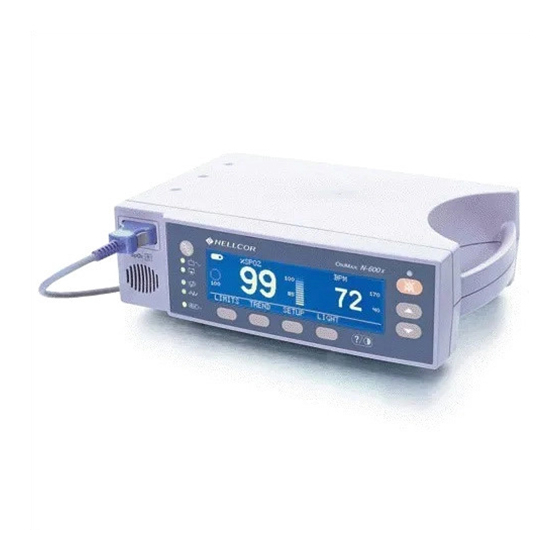
Page 11: Figure 1: N-595 Front Panel
Use with any particular patient requires the selection of an appropriate oxygen transducer as described in this Operator's Manual. Motion performance claims are applicable to models MAX-A, MAX-AL, MAX-P, MAX-N, and MAX-I Nellcor oximetry sensors. Through the use of the four softkeys, the operator can access trend information, select an alarm limit to be changed, choose the language to be used, adjust the internal time clock, and change communications protocol. -
Page 12: Figure 2: N-595 Rear Panel
Introduction 1. Equipotential Terminal (Ground) 4. Fuse Receptacle 2. AC Power Connector 5. Supply Voltage Selector Switch 3. Data Port Connector Figure 2: N-595 Rear Panel Figure 3 on page 4, Figure 4 on page 5, and Figure 5 on page 6 illustrate the various functions that are available through the use of the softkeys, and how to access them. -
Page 13: Figure 4: Trend Softkey Map
Introduction Figure 4: Trend Softkey Map N-595... -
Page 14: Related Documents
Documents know how to operate the monitor. Refer to the N-595 operator's manual. To understand the various Nellcor approved sensors that work with the monitor, refer to the individual sensor's directions for use. The latest version of the operator’s manual and the service manual are posted on the Internet at: http://www.mallinckrodt.com/respiratory/Serv_Supp/ProductManuals.html... -
Page 15: Routine Maintenance
1. Inspect the equipment for mechanical and functional damage. 2. Inspect safety labels for legibility. If the labels are damaged, contact Nellcor’s Technical Services Department, 1.800.635.5267, or your local Nellcor representative. Functional The following checks should be performed at least every 2 years by a qualified service technician. -
Page 16: Battery
Battery Nellcor recommends replacing the instrument's battery every 2 years. When the N-595 is going to be stored for 3 months or more, remove the battery prior to storage. To replace or remove the battery, refer to Disassembly Guide on page 51. -
Page 17: Performance Verification
The battery charge procedure should be performed before monitor repairs whenever possible. Tests Note: This section is written using Nellcor factory-set defaults. If your institution has preconfigured custom defaults, those values will be displayed. Factory defaults can be restored (see Reset Softkey, page 34). -
Page 18: Battery Charge
• The indicators remain lighted. • The LCD display shows NELLCOR and the software version of the N-595. Note: The software “Version” displayed in the example below is X.X.X.X.The actual software version will be displayed on your... - Page 19 Performance Verification • A 1-second beep sounds, indicating proper operation of the speaker, and all indicators turn off except the AC Power/Battery Charging indicator and the LCD screen. • The N-595 begins normal operation. PLETH VIEW: BLIP (MAGNIFIED) VIEW Power-On Defaults Note: When observing or changing alarm limits, a time-out is in effect and Alarm Range...
- Page 20 Performance Verification alarm limit for %SpO will indicate an alarm limit of “100” (or institutional default setting) inside a box. 3. Press and hold the ADJUST DOWN button. Verify that the boxed number for %SpO upper alarm limit reduces to a minimum of “86.” Note: A decimal point in the display indicates that the alarm limits have been changed from factory default values.
- Page 21 Performance Verification 9. Press the SELECT softkey three times. Verify that the monitor emits a beep after each keystroke. The Pulse upper alarm limit should be “170” and should be boxed. 10. Press and hold the ADJUST DOWN button. 11. Verify that the minimum displayed value is “41” for the BPM upper alarm limit.
- Page 22 Performance Verification 18. Press the LIMITS softkey. 19. Press the SELECT softkey two times. Verify that SatSeconds SAT-S alarm is selected. 20. Press the ADJUST UP button repeatedly and verify that the SatSeconds alarm display cycles from OFF through 10, 25, 50, 100, OFF. 21.
-
Page 23: Operational Setup
Performance Verification Operational Setup Operational set up procedures verify and setup the following parameters. • Alarms and Alarm Silence, page 15 • Alarm Volume Control, page 17 • Pulse Tone Volume Control, page 17 • Nurse Call, page 18 • Analog Output, page 19 •... - Page 24 Performance Verification 9. Press the ADJUST UP button until the SpO lower alarm limit indicates 10. Press the SELECT softkey three times to select pulse rate lower alarm limit. 11. Press the ADJUST UP button until the pulse rate lower alarm limit indicates 160.
- Page 25 Performance Verification 18. Press and release the ALARM SILENCE button. Verify that the monitor’s ALARM SILENCE indicator flashes. 19. Wait approximately 3 minutes. Verify that the monitor’s alarm does not return. After 3 minutes, the monitor’s alarm silence reminder beeps three times, and will continue to do so at approximately 3-minute intervals.
- Page 26 Performance Verification 3. Press the ADJUST UP button to return the beep volume to a comfortable level. 4. Remove the sensor from your finger. Disconnect the DOC-10 monitor cable and the sensor. Nurse Call 1. Data Port Connector 1. Connect the negative lead of a voltmeter to pin 5 and positive lead to pin 11 of the data port connector (1) on the back of the monitor.
- Page 27 Performance Verification and 15 and that there is continuity (60 ohms or less) between pins 7 and 8. Press the SRC-MAX tester %SpO button to change the %SpO to 90. 9. Use a DVM to verify that there is continuity between pins 8 and 15 and that there is no continuity between pins 7 and 15.
- Page 28 Performance Verification 8. Leave the negative lead connected to pin 10 and verify 1.0 ± 0.025 VDC on pins 13 and 14. This verifies the monitor’s BPM and Pleth function. Note: If step 8 takes more than 2 minutes to complete, the analog output will time out.
-
Page 29: General Operation
Operation with a Live Subject, page 22. LED Excitation Test This procedure uses normal system components to test circuit operation. A Nellcor O oxygen transducer, model MAX-A, is used to examine LED intensity control. The red LED is used to verify intensity modulation caused by the LED intensity control circuit. - Page 30 1. Sensor Port 1. Ensure that the monitor is connected to an AC power source. 2. Connect a DOC-10 pulse oximetry cable to the monitor sensor port. 3. Connect a Nellcor O MAX-A oxygen transducer to the pulse oximetry cable.
-
Page 31: Pulse Oximetry Functional Tests
Performance Verification 6. The monitor should stabilize on the subject's physiological signal in about 15 to 30 seconds. Verify that the oxygen saturation and pulse rate values are reasonable for the subject. Pulse Oximetry These tests utilizes the pulse oximetry functional tester (SRC-MAX) to verify Functional Tests the performance of the N-595 monitor. -
Page 32: Initial Setup
Performance Verification Initial Setup 1. Sensor Port 1. With the monitor turned off, connect the DOC-10 pulse oximetry cable to the sensor port (1). 2. Connect the SRC-MAX tester to the other end of the DOC-10 cable. 3. Turn on the monitor by pressing the POWER ON/OFF button. 4. - Page 33 Performance Verification 3. The monitor will display: • 90 %SpO • 60 BPM • no alarm • low level modulation Test #2: BPM 1. Press the SRC-MAX % PULSE RATE selection button. The SRC-MAX PULSE RATE 200 LED will light. 2.
- Page 34 Performance Verification 6. The monitor will display: • 90 %SpO • 60 BPM • no alarm • low level modulation Test #3: Modulation Level 1. Press the SRC-MAX % MODULATION selection button. The SRC- MAX % MODULATION LED will light. 2.
- Page 35 Performance Verification 6. The monitor will display: • 90 %SpO • 60 BPM • no alarm • low level modulation Test #4: Light 1. Press the SRC-MAX LIGHT LEVEL selection button. The SRC-MAX Light Level LED will light. 2. The monitor will waveform display will go flat and stabilizes at the low light level.
-
Page 36: Safety Tests
9-pin “D” type connector that has all pins shorted together. During these tests the monitor will be in a constant reset mode. That is, the “Nellcor” screen displays followed by a blank screen, then the “Nellcor” screen, the cycle repeats throughout the... -
Page 37: Power-On Settings And Service Functions
P o w e r - O n S e t t i n g s a n d S e r v i c e F u n c t i o n s Introduction This section discusses how to reconfigure power-on default values and access the service functions. -
Page 38: Adult Default Settings
Power-On Settings and Service Functions Table 2: Neonate Alarm Limit Factory Defaults Monitoring Mode Setting Note: Bold entries are different than adult default settings. Alarm Silence Duration Off Setting Disabled Alarm Silence Reminder Enabled Alarm Volume 5 of 10 Data Port Baud Rate 9600 Data Port Protocol ASCII... -
Page 39: Service Functions
%SpO Service Service functions can be used to select institutional defaults and to access information about the patient or instrument. Only a Nellcor Customer Service Functions Engineer should access some of the items available through the service functions. These items will be noted in the text that follows. - Page 40 Power-On Settings and Service Functions Note: The service function is only accessible from the main menu display. The menu bar will change to the headings listed Figure 6 on page 33. Note: If the above step is performed with a pulse oximetry cable connected, only the PARAM and EXIT softkeys appear on the screen.
-
Page 41: Exit Softkey
Power-On Settings and Service Functions Figure 6: Service Function Menu Exit Softkey The EXIT softkey returns the monitor to the Main menu. Next Softkey There are not enough softkeys to display all of the options that are available at some levels of the menu. Pressing the NEXT softkey allows you to view additional options available at a given menu level. -
Page 42: Print Softkey Menu
Power-On Settings and Service Functions Reset Softkey The RESET softkey can be used if any settings stored in memory have been changed from factory default values. If YES is pressed, the instrument sounds three tones and the settings return to factory default values. When NO is pressed, no changes are made to the settings stored in memory. - Page 43 Power-On Settings and Service Functions example, an instrument that is used 6 hours a week would take approximately 8 weeks to fill its memory. Note: The two-letter codes and the symbols that occur in the printout are described in Table 19 on page 104. Trend Softkey A Trend printout will include all data recorded for up to 48 hours of monitoring since the last Delete Trends was performed.
- Page 44 Power-On Settings and Service Functions ERRLOG Softkey This softkey is for Nellcor’s Customer Service Engineering Only. A list of all the errors recorded in memory can be obtained by pressing the ERRLOG softkey. The first line lists the type of instrument producing the printout, software level, type of printout, and the time of the printout.
-
Page 45: Next Softkey Menu
Power-On Settings and Service Functions INFO Softkey This softkey is for Nellcor’s Customer Service Engineering Only. Pressing the INFO softkey produces a single line printout of instrument information as illustrated below. The data presented in the printout, going from left to right, is the instrument type (N-595), software version level, type... - Page 46 Power-On Settings and Service Functions DOWNLD Softkey When the DOWNLD softkey is selected, the instrument will display the revision of the Boot Code. To exit DOWNLD, cycle power to the instrument by pressing the POWER ON/OFF button. Consult the Directions for Use (DFU) provided with any downloads or upgrades to the FLASH firmware.
- Page 47 Power-On Settings and Service Functions 2. Simultaneously press the LIGHT softkey and the CONTRAST softkey until the menu bar changes to the softkey headings shown below. 3. Press the NEXT softkey. 4. Press the ALARMS softkey. 5. Use the SELECT softkey to toggle between ALLOW OFF? and OFF REMINDER?.
-
Page 48: Setting Institutional Defaults (Sample)
Power-On Settings and Service Functions When ALLOW OFF is selected, a choice is given between allowing an audible Alarm Off or disabling the audible alarm OFF. Pressing the ADJUST UP or ADJUST DOWN button cycles between YES and NO. If YES is selected, the operator has the option of selecting AUDIBLE ALARM OFF. - Page 49 Power-On Settings and Service Functions 2. Set desired parameters to the institutional values. Refer to the N-595 operator’s manual for the procedures to set the values. 3. Simultaneously press the LIGHT softkey and the CONTRAST button until the menu bar changes to the softkey headings shown below. 4.
- Page 50 [This page intentionally left blank]...
-
Page 51: Troubleshooting
Who Should Only qualified service personnel should open the monitor housing, remove and replace components, or make adjustments. If your medical facility does Perform not have qualified service personnel, contact Nellcor’s Technical Services or Repairs your local Nellcor representative. Troubleshooting Problems with the N-595 are categorized in Table 4 on page 43. -
Page 52: Power
Troubleshooting Table 4: Problem Categories Problem Area Refer To 3. Display/Alarms Display/Alarms on page 46 • Display does not respond properly • Alarms and other tones do not sound properly or are generated without apparent cause 4. Operational Performance Operating Performance on page 47 •... -
Page 53: Buttons
Troubleshooting Table 5: Power Problems Condition Recommended Action The N-595 does not The battery may be discharged. To recharge the battery, operate when refer to Battery Charge on page 10. The monitor may disconnected from AC be used with a less than fully charged battery but with a power. -
Page 54: Display/Alarms
Troubleshooting Display/Alarms Table 7 on page 46 lists symptoms of problems relating to non-functioning displays and audible tones or alarms, and recommended actions. If the action requires replacement of a PCB or module, refer to Disassembly Guide on page 51. Table 7: Display/Alarms Problems Symptom Recommended Action... -
Page 55: Operational Performance
Troubleshooting Operational Table 8 on page 47 lists symptoms of problems relating to operational Performance performance (no error codes displayed) and recommended actions. If the action requires replacement of a PCB or module, refer to Disassembly Guide on page 51. Table 8: Operational Performance Problems Symptom Recommended Action... -
Page 56: Data Port
When an error code (other than the ones listed in Table 10 on page 49) is displayed, turn the instrument off and back on again. If the error code reappears, record it and notify Nellcor Technical Services Department. -
Page 57: Other Messages
Troubleshooting Table 10: Error Code Problems Error Possible Solution or Problem Meaning Code Identification Dead battery Refer to Table 5 on page 44. Institutional parameter lost User interface module: Institutional EEPROM section CRC corrupt Current settings lost User interface module: current EEPROM section CRC corrupt Clock setting lost Re-enter the date and time. - Page 58 Troubleshooting Invalid Silence An attempt has been made to set the alarm silence duration power-on default Duration to “OFF.” The power-on default cannot be set to “OFF.” Invalid SpO Limit An attempt has been made to set either the upper or lower alarm limit power-on default below 80.
-
Page 59: Disassembly Guide
D i s a s s e m b l y G u i d e Introduction The N-595 can be disassembled down to all major component parts, including: • PCBs • battery • cables • chassis enclosures The following tools are required: •... -
Page 60: Prior To Disassembly
Disassembly Guide Prior to Disassembly 1. Turn the N-595 off by pressing the POWER ON/OFF button. 2. Disconnect the monitor from the AC power source. Fuse 1. Complete the procedure in paragraph Prior to Disassembly on page 52. Replacement 2. Disconnect the power cord from the back of the monitor. 3. -
Page 61: Monitor Disassembly
Disassembly Guide Monitor 1. Complete the procedure in paragraph Prior to Disassembly on page 52. Disassembly 2. Set the N-595 upside down, as shown in Figure 8 on page 53. Figure 8: Corner Screws 3. Remove the monitor’s four corner screws. Caution: Observe ESD (electrostatic discharge) precautions when disassembling and reassembling the N-595 and when handling any of the components of the N-595. -
Page 62: Monitor Assembly
Disassembly Guide Figure 9: Separating Case Halves Monitor 1. Connect the monitor’s Power Supply to J16 on the User Interface PCB. Assembly 2. Place the monitor’s top case over the bottom case, being careful to align the Display PCB, Power Entry Module, and the fan with the slots in the case halves. -
Page 63: Battery Replacement
Figure 10: Removing the Battery 4. The lead-acid battery is recyclable. Do not dispose of the battery by placing it in the regular trash. Dispose of the battery in accordance with local guidelines or return it to Nellcor’s Technical Services for disposal. N-595... -
Page 64: Replacement
Disassembly Guide Replacement 5. Connect the leads to the battery. The red wire connects to the positive terminal, and the black wire connects to the negative terminal. 6. Insert the new battery into the bottom case with the negative terminal towards the outside of the monitor. -
Page 65: Replacement
Disassembly Guide Figure 11: Power Entry Module Replacement 4. Reconnect the three power supply leads as indicated in Table 11 on page 59. 5. Install the PEM in the bottom case with the fuse drawer facing down. A tab in the bottom case holds the PEM in place. Insert the bottom wing of the PEM between the tab and the internal edge of the sidewall of the bottom case. -
Page 66: Power Supply Removal/Replacement
Disassembly Guide Power Supply Removal/ Replacement Removal 1. Follow the procedure in paragraphs Prior to Disassembly on page 52, and Monitor Disassembly on page 53. 2. Push the top of the Power Entry Module (PEM) in from the outside of the case, and lift up. -
Page 67: Replacement
Disassembly Guide Figure 12: Power Supply Replacement 8. Reconnect the leads to the PEM following the instructions in Table 11 on page 59, and Figure 11 on page 57. Table 11: Power Supply Lead Connections Wire Color / Label Connect To Green &... -
Page 68: Cooling Fan Removal/Replacement
Disassembly Guide 10. Install the seven screws in the Power Supply and tighten. 11. Connect the fan harness to J1 on the Power Supply. 12. Install the PEM in the bottom case with the fuse drawer facing down. A tab in the bottom case holds the PEM in place. Insert the bottom wing of the PEM between the tab and the internal edge of the sidewall of the bottom case. -
Page 69: Replacement
Disassembly Guide Figure 13: Cooling Fan Replacement 4. Connect the cooling fan wire harness to J1 on the Power Supply PCB. 5. Insert the cooling fan into the slots in the bottom case with the padded sides on the top and bottom and the fan's harness to the handle side of the case. -
Page 70: Display Pcb Removal/Replacement
Disassembly Guide Display PCB Removal/ Replacement Removal WARNING: The LCD panel contains toxic chemicals. Do not ingest chemicals from a broken LCD panel. 1. Complete the procedures in paragraphs Prior to Disassembly on page 52, and Monitor Disassembly page 53. 2. -
Page 71: Replacement
Disassembly Guide Figure 14: Display PCB Replacement 6. Install new double-sided tape as shown in Figure 14 on page 63. 7. Slide the Display PCB into the grooves in the top case. Check to make sure the Display PCB is firmly seated in the top case. Apply pressure between the top case and the display PCB to make good contact with the double-sided tape. -
Page 72: User Interface Pcb Removal/Replacement
Disassembly Guide 10. Complete the procedure in paragraph Monitor Assembly page 54. User Interface PCB Removal/ Replacement Removal 1. Complete the procedures in paragraphs Prior to Disassembly page 52, and Monitor Disassembly page 53. 2. Disconnect the CCFL harness (two white wires) from J5 of the User Interface PCB. -
Page 73: Replacement
Disassembly Guide Figure 15: User Interface PCB Replacement Caution: When installing the User Interface PCB, hand tighten the five screws to a maximum of 4 inch-pounds. Over-tightening could strip out the screw holes in the top case, rendering it unusable. 8. -
Page 74: Alarm Speaker Removal/Replacement
Disassembly Guide 11. Connect the speaker cable to J12 of the User Interface PCB. 12. Connect the CCFL wire harness with two white wires to J5 of the User Interface PCB. 13. Connect the Display PCB ribbon cable to J13 of the User Interface PCB. Install the clip over the J13 connector. -
Page 75: Replacement
Disassembly Guide Figure 16: Alarm Speaker Replacement 4. Pull the holding clip back, and insert the speaker into the top case. 5. Connect speaker wire harness to J12 on the User Interface PCB. 6. Complete the procedure in paragraph Monitor Assembly page 54. N-595... - Page 76 [This page intentionally left blank]...
-
Page 77: Spare Parts
Nellcor's Technical Services provides technical assistance information and replacement parts. To obtain replacement parts, contact Nellcor or your local Replacement Nellcor representative. Refer to parts by the part names and part numbers. Parts Spare parts and accessories for the N-595 are listed on the Internet at: http://mallinckrodt.com/respiratory/resp/Serv_Supp/Apartweb/main/PartAcceMenu.html... -
Page 78: Figure 17: Exploded View
Spare Parts Table 12: Parts List Item Description Power Cord (not shown) Tilt Stand (not shown) GCX Mounting Kit (not shown) Figure 17 on page 70 shows the N-595 expanded view with numbers relating to the spare parts list. Figure 17: Exploded View... -
Page 79: Packing For Shipment
Return the N-595 by any shipping method that provides proof of delivery. General Pack the monitor carefully. Failure to follow the instructions in this section may result in loss or damage not covered by any applicable Nellcor warranty. Instructions If the original shipping carton is not available, use another suitable carton;... -
Page 80: Figure 18: Packing
Packing for Shipment Figure 18: Packing 2. Place in shipping carton and seal carton with packing tape. 3. Label carton with shipping address, return address, and RGA number, if applicable. -
Page 81: Repacking In A Different Carton
Packing for Shipment Repacking in a If the original carton is not available, use the following procedure to pack the N-595: Different Carton 1. Place the monitor in a plastic bag. 2. Locate a corrugated cardboard shipping carton with a bursting strength of at least 200 pounds per square inch (psi). - Page 82 [This page intentionally left blank]...
-
Page 83: Specifications
N-595. Saturation accuracy will vary by sensor type. Refer to the Sensor Accuracy Grid. Applicability: O MAX-A, MAX-AL, MAX-P, MAX-I, and MAX-N sensors. Specification applies to monitor performance and was validated with Biotek and Nellcor simulators. Pulse Rate 20 to 250 ± 3 digits Without Motion With Motion normal physiologic range (e.g., 55 - 125 bpm) ±... -
Page 84: Electrical
Specifications Electrical Instrument Power Requirements rated at 108 to 132 volts AC (nominal 120 VAC) or 200 to 240 volts AC (nominal 230 VAC), 20 volt/ amps to be compliant with IEC 60601-1 sub-clause 10.2.2 Fuses qty 2, 0.5 A, 250 volts, slow-blow, IEC (5 x 20 mm) Battery The battery provides at least 2 hours of battery life when new and fully charged with no alarms, no serial data, no analog output, no nurse call output, with... - Page 85 Specifications Transport and Storage (not in shipping container) Temperature -20 ºC to 60 ºC (-4 ºF to 140 ºF) Altitude/Barometric Pressure -390 m to 4,572 m (-1,280 ft. to 15,000 ft.) 50 kPa to 106 kPa (31.3 in. Hg to 14 in. Hg) Relative Humidity 15% to 95% non-condensing over tem- perature range of...
-
Page 86: Physical Characteristics
Specifications Physical Characteristics Weight 5.7 lbs. (2.6 kg) Dimensions 3.3 in. x 10.4 in. x 6.8 in. (8.4 cm x 26.4 cm x 17.3 cm) Compliance Item Compliant With Equipment classification Safety Standards: IEC 60601-1 (same as EN60601-1), CSA 601.1, UL 2601-1, EN865, EN/IEC 60601-1-2 (second edition) Type of protection... - Page 87 Specifications Item Compliant With Environmental IEC 60601-1, sub-clause 44.5 Cleaning IEC 60601-1, sub-clause 44.7 Case surface made of non-toxic IEC 60601-1, sub-clause 48 materials Case resistant to heat and fire IEC 60601-1, sub-clause 59.2(b) N-595 power entry module fuse IEC 60601-1, sub-clause 59.3 holder N-595 exterior markings IEC 60601-1, sub-clause 6.1, 6.3, and 6.4;...
-
Page 88: Manufacturer's Declaration
Specifications Item Compliant With Electrical fast transient/burst IEC 61000-4-4, level 3 immunity Manufacturer’s Declaration WARNING: The use of accessories, transducers, and cables other than those specified may result in increased emission and/or decreased immunity of the N-595 pulse oximeter. Table 13: Electromagnetic Emissions (IEC 60601-1-2) The N-595 is suitable for use in the specified electromagnetic environment. -
Page 89: Table 14: Electromagnetic Immunity (Iec 60601-1-2)
Specifications Table 14: Electromagnetic Immunity (IEC 60601-1-2) The N-595 is suitable for use in the specified electromagnetic environment. The customer and/or user of the N-595 should assure that it is used in an electromagnetic environment as described below. IEC 60601-1-2 Compliance Electromagnetic Immunity Test... - Page 90 Specifications Table 14: Electromagnetic Immunity (IEC 60601-1-2) The N-595 is suitable for use in the specified electromagnetic environment. The customer and/or user of the N-595 should assure that it is used in an electromagnetic environment as described below. IEC 60601-1-2 Compliance Electromagnetic Immunity Test...
-
Page 91: Table 15: Electrostatic Immunity (Iec 60601-1-2)
Specifications Table 15: Electrostatic Immunity (IEC 60601-1-2) The N-595 is suitable for use in the specified electromagnetic environment. The customer and/or user of the N-595 should assure that it is used in an electromagnetic environment as described below: IEC 60601-1- Compliance Electromagnetic Immunity Test... -
Page 92: Table 16: Recommended Separation Distances
Specifications Table 16: Recommended Separation Distances Recommended Separation Distances between Portable and Mobile RF Communications Equipment and the N-595 (IEC 60601-1-2) Frequency of 150 kHz to 80 MHz to 800 MHz to Transmitter 80 MHz 800 MHz 2.5 GHz Equation d = 1.2√P d = 1.2√P d = 2.3√P... -
Page 93: Table 17: Cables (Iec 60601-1-2)
Specifications Table 17: Cables (IEC 60601-1-2) Cables and Maximum Complies With Sensors Length DOC-10 pulse 10 ft. (3 m) • RF emissions, CISPR 11, oximetry cable Class B/Group 1 • Harmonic emissions, IEC 61000-3-2 Software 10 ft. (3 m) • Voltage fluctuations/flicker emission, download cable, IEC 61000-3-3 RS-232 serial,... -
Page 94: Safety Tests
Specifications Table 17: Cables (IEC 60601-1-2) Cables and Maximum Complies With Sensors Length 3 feet (0.91 m) • RF emissions, CISPR 11, Durasensor Class B/Group 1 sensor • Harmonic emissions, IEC 61000-3-2 DS-100A • Voltage fluctuations/flicker emission, IEC 61000-3-3 • Electrostatic discharge (ESD), IEC 61000-4-2 •... -
Page 95: Enclosure Leakage Current
Specifications Enclosure Leakage Current Power Line AAMI/ANSI AC Line Neutral Line Ground IEC 60601-1 Standard Cord Cord Cable Closed Closed Closed 100 µA 100 µA 500 µA 300 µA Closed Closed Open Closed Open Closed 500 µA 300 µA 500 µA 100 µA Open Closed... - Page 96 [This page intentionally left blank]...
-
Page 97: Data Port Interface Protocol
Introduction When connected to the data port on the back of the N-595, printouts can be obtained or patient data can be communicated to a Nellcor Oxinet II monitoring system, Nellcor Intouch Remote Oximetry Notification System or personal computer (PC). Analog signals representing %SpO , pulse rate, and pulse amplitude are also provided by the data port. -
Page 98: Figure 19: Data Port Setup
Data Port Interface Protocol Figure 19: Data Port Setup... -
Page 99: Communication Baud Rate
The selections are: • ASCII used for printouts • OXINET to enable communication with Oxinet II • CLINICAL intended for Nellcor use only • GRAPH for graphic printouts • AGILEN interfaces the N-595 with an Agilent (HP) monitor N-595... -
Page 100: Language Selection
Data Port Interface Protocol • SPACELBS interfaces the N-595 with a SpaceLabs monitor • MARQ interfaces the N-595 with a GE Marquette monitor • DATEX interfaces the N-595 with a Datex-Ohmeda AS/3 monitor Note: Selecting AGILEN, SPACELBS, MARQ, or DATEX automatically sets the baud rate to the rate applicable for that protocol. -
Page 101: Nurse Call Setup
Data Port Interface Protocol 2. Press the SETUP softkey. 3. Press the NEXT softkey. 4. Press the LANG softkey. 5. Use the ADJUST UP and ADJUST DOWN buttons to select the desired language. 6. Press the EXIT softkey to save the language setting. Nurse Call Setup The voltage polarity for the Nurse Call, available at pins 11 and 5, can be selected through the softkeys. -
Page 102: Analog Calibration Setup
Data Port Interface Protocol 5. Press the NCALL softkey. 6. Press the NORM+ (+5 to +12 VDC) or NORM- (-5 to -12 VDC) softkey as required for your nurse call system. Analog Calibration Analog calibration signals are provided to adjust a recorder to the output of Setup the instrument. -
Page 103: Agilent (Hp) Communications
(A05 option) to interface with the N-595 pulse oximeter. The RS-232 hardwire interface cable has a DB-15 connector for the N-595 and the applicable connector for the Agilent monitor. Nellcor cable part number 902256 is recommended for this interface. -
Page 104: Marquette Communications
Datex-Ohmeda The Datex-Ohmeda monitor AS/3 must be configured for communications Communications with the Nellcor N-200 monitor in order to communicate with the N-595 monitor. Refer to the AS/3 operator's manual for instructions on configuring the AS/3 monitor. The N-595 sends SpO , pulse rate, and alarm status data to the Datex AS3 monitor. -
Page 105: Connecting To The Data Port
Data Port Interface Protocol The RS-232 hardwire interface cable has a DB-15 connector for the N-595 and the applicable connector for the Datex monitor. Nellcor cable part number 902255 is recommended for this interface. Corrupt data will be indicated by a Communications Error displayed on the Datex monitor. -
Page 106: Communication With A Pc
Data Port Interface Protocol Table 18: Data Port Pin Outs Signal RXD- (R-422 negative output) Signal Ground (isolated from earth ground) Nurse Call (RS-232 level output [-5 to -12 VDC with no audible alarm] [+5 to +12 VDC with audible alarm]) TXD- (RS-422 negative output) AN_Pulse (analog pulse rate) AN_Pleth (analog pleth waveform output) -
Page 107: Dump Instrument Info (Option 1)
This allows Instrument Info to be printed or displayed on the PC screen. This Info (Option 1) option is intended for Nellcor’s field service personnel. Instrument Info is a single line of data, which includes software version, CRC number, and total operating time. -
Page 108: Dump Error Log (Option 4)
This option is intended for Nellcor’s field service personnel. Exit Interactive Selecting option 5 exits the interactive mode and returns the data port to Mode (Option 5) normal operation. -
Page 109: Column Heading
Data Port Interface Protocol Figure 21: Real-Time Printout Column Heading To explain the printout, it is necessary to break it down to its key components. The first two lines of the chart are the Column Headings shown below. Every 25th line a Column Heading is printed. A column heading is also printed whenever a value of the Column Heading is changed. -
Page 110: Alarm Limits
Data Port Interface Protocol Data Source Data in the highlighted box above represents the source of the printout or display, in this case the N-595. Software Revision Level The next data field tells the user the software level (Version X.X.X.X) and a software verification number (CRC XXXX). -
Page 111: Patient Data And Operating Status
Data Port Interface Protocol Patient Data and Operating Status Time The Time column represents the N-595 real-time clock. Patient Data Patient data and the operating status of the unit are highlighted in the display above. Parameter values, at the time of the printout, are displayed directly beneath the heading for each parameter. -
Page 112: Trend Data Printout (Ascii Mode)
Data Port Interface Protocol Table 19: Operating Status Codes Code Meaning Alarm Off Alarm Silence Battery in Use Low Battery Loss of Pulse with Motion Loss of Pulse MOtion Pulse Rate Upper Limit Alarm Pulse Rate Lower Limit Alarm Pulse Search Sensor Disconnect Saturation Upper Limit Alarm Saturation Lower Limit Alarm... -
Page 113: Trend Printout (Graph Mode)
Data Port Interface Protocol Figure 22: Trend Data Printout (ASCII Mode) Trend Printout The graph mode (Figure 23 and Figure 24) disables all printout functions (Graph Mode) except trend data. Trend printouts will be graphical if connected to a serial printer that supports Epson ESC protocol. -
Page 114: Analog Output
Data Port Interface Protocol pins 10 and 11 will be -5 VDC to -12 VDC, or +5V DC to +12 VDC, depending on the option chosen via the softkeys (either NORM+ or NORM-). Whenever there is an audible alarm, the output between pins 5 and 11 will reverse polarity. - Page 115 Data Port Interface Protocol stair step signal. The stair step signal will start at 0.0 VDC and increase up to 1.0 VDC in 0.1 VDC increments. Each increment will be held for 1 second. Through use of the softkeys, the 0.0 VDC, 1.0 VDC, or stair step signal can be selected individually (see Analog Output page 19).
- Page 116 [This page intentionally left blank]...
-
Page 117: Technical Discussion
T e c h n i c a l D i s c u s s i o n Oximetry The N-595 uses pulse oximetry to measure functional oxygen saturation in the blood. Pulse oximetry works by applying a sensor to a pulsating arteriolar Overview vascular bed, such as a finger or toe. -
Page 118: Automatic Calibration
Technical Discussion Automatic Because light absorption by hemoglobin is wavelength dependent and Calibration because the mean wavelength of LEDs varies, an oximeter must know the mean wavelength of the sensor's red LED to accurately measure SpO . During manufacturing, the mean wavelength of the red LED is encoded in a resistor in the sensor. -
Page 119: Satseconds Alarm Management
For a definition of motion, as applicable to the N-595, contact Nellcor's Technical Services Department. The N-595 pulse oximeter is designed to use Nellcor brand sensors containing technology. These sensors can be identified by the deep blue color of Technology their plug. - Page 120 Consult the accuracy card included with the pulse oximeter for specific accuracy information for the N-595 with different Nellcor approved sensors. The N-595 uses the information in the O -compatible sensor to tailor troubleshooting messages for the clinician.
-
Page 121: Block Diagram Theory
Technical Discussion Block Diagram The monitor block diagram is shown in Figure 26 on page 113. Theory Figure 26: Block Diagram The N-595 main printed circuit board (PCB) consists of three main parts: • The Secondary Input Port/Secondary Output Port (SIP/SOP) •... - Page 122 Technical Discussion The microprocessor is responsible for interacting with the analog front end, and communicates with the front end through control signals. The microcontroller receives the analog voltages from the front end analog-to- digital (A/D) converters. The resultant data is used to calculate SpO pulse rate values.
-
Page 123: Schematic Diagrams And Assembly Drawings
Technical Discussion The patient is connected to the N-595 via a sensor and pulse oximetry cable. The SpO analog front end drives the sensor’s LEDs, conditions the incoming signal, and provides adjustable gain status. The microprocessor measures the sensor’s analog outputs and continually controls the gain stages and LED drive current to ensure that the signals are within the measurement range. - Page 124 Technical Discussion Figure 42: Linear Power Supply Schematic Diagram Figure 43: Linear Power Supply Assembly Drawing...
- Page 125 Figure 27 Main PCB Schematic Diagram (Sheet 1 of 13)
- Page 126 Figure 28 Main PCB Schematic Diagram (Sheet 2 of 13)
- Page 127 Figure 29 Main PCB Schematic Diagram (Sheet 3 of 13)
- Page 128 Figure 30 Main PCB Schematic Diagram (Sheet 4 of 13)
- Page 129 Figure 31 Main PCB Schematic Diagram (Sheet 5 of 13)
- Page 130 Figure 32 Main PCB Schematic Diagram (Sheet 6 of 13)
- Page 131 Figure 33 Main PCB Schematic Diagram (Sheet 7 of 13)
- Page 132 Figure 34 Main PCB Schematic Diagram (Sheet 8 of 13)
- Page 133 Figure 35 Main PCB Schematic Diagram (Sheet 9 of 13)
- Page 134 Figure 36 Main PCB Schematic Diagram (Sheet 10 of 13)
- Page 135 Figure 37 Main PCB Schematic Diagram (Sheet 11 of 13)
- Page 136 Figure 38 Main PCB Schematic Diagram (Sheet 12 of 13)
- Page 137 Figure 39 Main PCB Schematic Diagram (Sheet 13 of 13)
- Page 138 Figure 40 Main PCB Assembly Drawing (Front View)
- Page 139 AT11 AT12 AT14 AT15 AT10 AT13 AT16 AT17 AT18 AT19 AT20 AT28 AT23 AT24 AT25 AT21 AT26 AT22 AT29 AT27 AT34 AT33 AT31 AT30 AT35 N595 MAIN REV A AT32 AT48 AT43 AT70 AT194 AT44 AT36 AT39 AT175 AT40 AT45 AT46 AT42 AT47...
- Page 140 10.0K 1.00K 0.1U 10.0K LM358 1.00K IRF9510 10.0K 73.2K 10.0K 10.0K VREF LM358 10.0K 2N7002S Requires Heat Sink FAN_CTRL Nellcor # 891196 VOUT 10.0K LM385S LM35D 10.0K 1N914S MBRS330T3 MTS50B 0.1U 154K CHG_OUT BATT+ Battery + 10.0M 2ASB 1N914S Battery - 100K 49.9K...
- Page 141 FERRITE DC FERRITE Figure 43 Linear Power Supply Assembly Drawing...
- Page 142 Index I n d e x Accessories on Internet 6 Adult Default Settings 30 Agilent (HP) Communications 95 Alarm Management, SatSeconds 111 Alarm Off 40, 104 Alarm Range Limits 11 Alarm Silence 15, 104 Alarm Speaker Replacement 66 Alarm Volume Control 17 Alarms Softkey 38 Altitude 76, 77 Analog Calibration Setup 94...
- Page 143 Index Disassembly Guide 51 Disinfecting 7 Display PCB Replacement 62 Downld Softkey 38 Dump Error Log 100 Dump Instrument Info 99 Dump Trend 99 Electromagnetic Emissions 80 Electromagnetic Immunity 81 Electrostatic 83 Electrostatic Immunity 83 Equipment Needed 9 Errlog Softkey 36 Error Codes 48 Error Log Dump 100 Exit Softkey 33...
- Page 144 Index Accuracy and Motion Tolerance 75 Measurement Range 75 Monitor Assembly 54 Monitor Description 2 Monitor Disassembly 53 MOtion 104 Neonate Default Settings 29 Next Softkey 33, 37 Nurse Call 18, 105 Nurse Call Relay Pin States 106 Nurse Call Relay Rating 106 Nurse Call Setup 93 Operating Relative Humidity 76...
- Page 145 Index Real-Time Printout 100 Rear Panel 4 Recommended Separation Distances 84 Related Documents 6 Repacking in a Different Carton 73 Repacking in Original Carton 71 Replacement Level Supported 51 Reset Softkey 34 Returning the N-595 71 Routine Maintenance 7 Routine Service 7 Safety Analyzer 9 Safety Tests 28 SatSeconds Alarm Management 111...
- Page 146 Index Trend Softkey Map 5 Troubleshooting Guide 43 User Interface PCB Replacement 64 Using Data on the PC 100 Warnings - Definition 1 Who Should Perform Repairs 43 N-595...
- Page 147 Nellcor Puritan Bennett Inc. 4280 Hacienda Drive Pleasanton, CA 94588 USA Telephone Toll Free 1.800.NELLCOR Tyco Heathcare UK LTD 154 Fareham Road Gosport PO13 0AS, U.K. Telephone +44.1329.224000 Rx ONLY © 2001 Nellcor Puritan Bennett Inc. All rights reserved. 061661A-0901...
Need help?
Do you have a question about the OXIMAX N-595 and is the answer not in the manual?
Questions and answers