Nellcor N-180 Manual
Hide thumbs
Also See for N-180:
- Service manual (83 pages) ,
- Operator's manual (42 pages) ,
- Preliminary service manual (83 pages)
Table of Contents
Advertisement
Quick Links
SECTION 1: INTRODUCTION
MANUAL OVERVIEW
WARNINGS, CAUTIONS, AND NOTES
Warning
Caution
Note
N-180/N-180E PULSE OXIMETER MONITORS DESCRIBED
Manual Overview
Warnings, Cautions, and Notes
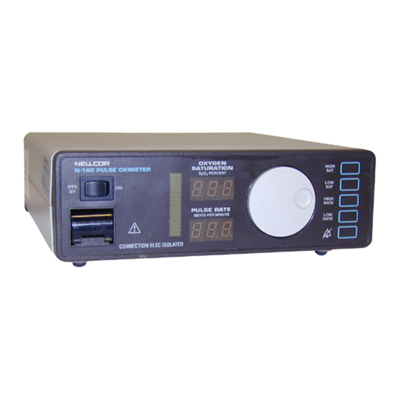
N-180 Pulse Oximeter Monitor Description
Related Documents
Conventions Used in this Manual
Returning the Monitor
This manual contains information for servicing the Nellcor N-180 pulse
oximeter, and is only for individuals who have a technical background in
analog and digital electronics. This product must beserviced by qualified
personnel. Before servicing the N-180, read the operator's manual carefully
for a thorough understanding of how this device operates.
This manual uses three terms that are important for proper operation of the
monitor: Warning, Caution, and Note.
A warning precedes an action that may result in injury or death to the patient
or user. Warnings are boxed and highlighted in boldface type.
Warning:
This is an example of a warning. This is an
example of a warning. This is an example of a
warning.
A caution precedes an action that may result in damage to, or malfunction of,
the monitor. Cautions are highlighted in boldface type.
Caution:
This is an example of a caution. This is an example of a
caution. This is an example of a caution
A note gives information that requires special attention. Here is an example:
Note:
This is an example of a note. This is an example of a note. This
is an example of a note. This is an example of a note.
The N-180/N-180E Pulse Oximeter Monitors (to simplify writing and reading
this manual, the term monitor is substituted from this point on) continuously
and noninvasively measures functional oxygen saturation of arterial hemo-
globin (SpO
), and pulse rate. Measurements are updated at each pulse beat.
2
These monitors are manufactured in a domestic and an international
configuration. The domestic version uses standard English markings; the
international version uses symbolic markings. Except where there is a clear
1-1
Advertisement
Table of Contents

Related Manuals for Nellcor N-180


Summary of Contents for Nellcor N-180
-
Page 1: Section 1: Introduction
Conventions Used in this Manual Returning the Monitor MANUAL OVERVIEW This manual contains information for servicing the Nellcor N-180 pulse oximeter, and is only for individuals who have a technical background in analog and digital electronics. This product must beserviced by qualified personnel. -
Page 2: Related Documents
To perform test and troubleshooting procedures and to understand the principles of operation and circuit analysis sections of this manual, you must know how to operate the monitor. Refer to Operators Manual Nellcor N-180 Pulse Oximeter or to Operators Manual Nellcor N-180E Pulse Oximeter, as applicable. -
Page 3: Section 2: Principles Of Pulse Oximetry
SECTION 2: PRINCIPLES OF PULSE OXIMETRY Introduction Automatic Calibration Functional Versus Fractional Saturation Measured Versus Calculated Saturation INTRODUCTION Pulse oximetry is based on two principles: that oxyhemoglobin and deoxyhe- moglobin differ in their absorption of red and infrared light, and that the vol- ume of arterial blood in tissue (and hence, light absorption by that blood) changes during the pulsatile cycle. -
Page 4: Measured Versus Calculated Saturation
N-180 Pulse Oximeter Service Manual fractional saturation functional SpO x 100 100 - (% carboxyhemoglobin + % methemoglobin) MEASURED VERSUS CALCULATED SATURATION When saturation is calculated from a blood gas measurement of the partial pressure of arterial oxygen (PaO ), the calculated value may differ from mea- sured SpO . -
Page 5: Section 3: Functional Block And Circuit Analysis
SECTION 3: FUNCTIONAL BLOCK AND CIRCUIT ANALYSIS Introduction Functional Block Analysis Circuit Analysis INTRODUCTION This section explains how monitor circuits operate and contains two parts. • Functional block diagram analysis • Circuit analysis FUNCTIONAL BLOCK ANALYSIS Monitor functional elements (figure FOG-1) include: •... - Page 6 SAT signal is accomplished by circuits in the filter block. Input Source Selection There are two possible inputs to the oximetry module. These inputs are controlled via the LEMO signal. Only one input is used in the model N-180,...
- Page 7 Section 3: Functional Block and Circuit Analysis the differential input at JP1. If more than one input were used, the input source selection logic detects which input connector is active. Connector JP1 goes to an internal preamplifier. The signal at connector JP3 requires an external preamplifier.
-
Page 8: Circuit Analysis
The SAT signal development scheme requires lighting the measurement site using specific light wavelengths. Nellcor sensors have two LED sources, infrared (IR) and red. These LED sources are an integral part of each Nellcor oxygen transducer. The LEDs are alternately pulsed on and off by the oximetry module microprocessor. - Page 9 Section 3: Functional Block and Circuit Analysis switches U4A and U4B via control lines IRLED* (U4 pin 16) and REDLED* (U4A, pin 1). The DAC outputs are gated by these signals and output on pin 2 and pin 15 of U4. Drive I R I R 0.5V-...
- Page 10 Input Source Selection Circuits The SAT signal is developed by the photodiode in the Nellcor sensor (figure 3- 3), responding to the transmitted red and IR light at the measurement site. The transmitted light intensity depends on the LED drive level, the patient’s oxygen saturation, and the amplitude of the pulse at the site.
- Page 11 40 ±1 bpm (39 to 41 bpm). Note that pocket tester pulse rate is dependent on LED switching rate and may differ on other Nellcor pulse oximeter models. The SAT signal from the pocket tester is coupled to the SAT conditioning circuits via the sensor input to JP1 (pin 1 and pin 4) on the oximetry module PCB.
- Page 12 N-180 Pulse Oximeter Service Manual developed in the module. This calibration voltage ( 2) is sent to the VCALIN analog to digital converter by buffer U21B. Input Amplifier and Synchronous Detector Refer to figure 3-4 and figure FO10-1 (sheet 3 of 7 and 4 of 7). The SAT signal...
- Page 13 Section 3: Functional Block and Circuit Analysis Bandpass Filter Programmable Gain Stage Compare 1 10Hz Gain 0.004 to 1 in 255 Steps 200 Hz 260 kHz SAT Signal – DAC U9 U13B I R I R U7A LED 8.57V- U13A Control DATABUS (0..7) U14B...
- Page 14 N-180 Pulse Oximeter Service Manual Demodulator Filters and Amplifiers There are three circuits in the demodulation and filtering block: • Circuits that gate other logic • IR Filter and amplifier • Red Filter and amplifier Gate logic: ■ Field effect (FET) switches U15A and U15B separate the information in the SAT signal from the red information (figure FO10-1 3 of 7).
- Page 15 Section 3: Functional Block and Circuit Analysis and 2). Likewise, the next two phases (3 and 4) are gated into the RED filter and amplifier. This leaves a 483 microsecond period until the next pair of IR pulses is gated into the IR filter and amplifier. The overall pulse amplitudes are proportional to the transmitted light at the measurement site.
- Page 16 N-180 Pulse Oximeter Service Manual Control signals: ■ Refer to figure FO10-1 (sheet 4 of 7 and sheet 7 of 7). Measuring SpO controlled by logic signals from micro controller U5. The control signals are listed and defined below: IRGATE* is a result of micro controller output PWM1* ANDed with output CMT1.
- Page 17 Section 3: Functional Block and Circuit Analysis U24A VCAL1 U24B RED _ ADC IR _ ADC U24C U24D VCAL 2 Dual Channel Serial RESISTORS Output 2.5V Ref ADCDATA ADCCHN REF2.5 Figure 3-5: Oximetry Module Analog to Digital Conversion Circuits Support Circuits Support circuits include the following: •...
- Page 18 N-180 Pulse Oximeter Service Manual Oximetry Support Circuits: ■ Oximetry module support circuits consist of 80C522 micro controller U5 (figure FO10-1, sheet 7 of 7), ROM U6, and RAM U12, all served by octal latch U2. Serial-to-parallel shift register U16 outputs parallel data for .
- Page 19 Section 3: Functional Block and Circuit Analysis CPU PCB The CPU PCB: • controls display functions • manages the RS-232 link to external devices • has multiple support circuits – speaker drive – LED current check – battery condition monitor –...
- Page 20 N-180 Pulse Oximeter Service Manual therefore LOWBAT remains a logic low. The processor responds by not turning on the BATT IN USE light. Battery Operation ■ When the monitor operates on battery, VPS drops to approximately 13 V. When BAT_THRESH is brought to logic low, the resulting voltage at U4B, pin 6, is below the 2.5 V reference (typically 2 V) and the...
- Page 21 Section 3: Functional Block and Circuit Analysis Standby to on ■ When the ON/STD BY switch is placed in the ON position, the STBY_COM and ON poles of the switch are connected. Capacitor C13 discharges through R22, producing a positive spike into gate U13D. U13D inverts the spike that sets FF U14B and discharges C14 through D7.
- Page 22 N-180 Pulse Oximeter Service Manual the drive to Q8, which in turn reduces the charging voltage, whereupon the cycle continues. Should the battery or battery input circuit encounter a short, the voltage at the sense point (R53 and R54) drops; accordingly, Q10 attempts to increase the charge current.
- Page 23 Section 3: Functional Block and Circuit Analysis isolators. Device U10 is a level adjuster. Device U-18 inductors A–H reduce electromagnetic interference. LED Current Check Circuits (Sheet 4 of 4) When power is applied, the monitor housekeeping diagnostics check the current flowing to the LEDs to determine if any LED is malfunctioning in a way that could lead to the misinterpretation of the LED presentation.
- Page 24 N-180 Pulse Oximeter Service Manual • BATT IN USE (LD1) • LOW BATT (LD2) • PULSE SEARCH (LD3) • NEONATAL (LD4) • HIGH SAT (LD13) • LOW SAT (LD14) • HIGH RATE (LD15) • LOW RATE (LD16) • AUDIO ALARM OFF (LD17) and operational information, •...
-
Page 25: Section 4: Routine Maintenance
SECTION 4: ROUTINE MAINTENANCE Introduction Nellcor Recommendation INTRODUCTION The only routine service required is that which is mandated by your institution and local or national agencies. NELLCOR RECOMMENDATION Nellcor recommends replacing the monitor 12 volt battery every 2 years. -
Page 27: Section 5: Troubleshooting
OBTAINING REPLACEMENT PARTS Nellcor Technical Services provides technical assistance information and re- placement parts. To obtain replacement parts, contact Nellcor. Refer to parts by the part names and part numbers listed in Section 9, Spare Parts. TROUBLESHOOTING GUIDE Symptoms can occur in one or more of the following categories: •... - Page 28 Generally, the first problem listed is the most common or the easiest to verify. If you experience a symp- tom not listed in this section, please contact Nellcor Technical Service in Hayward, California.
- Page 29 Section 5: Troubleshooting You see CHE LED displayed for a few seconds; then, 0 is displayed.. You can then sequentially light each LED segment by slowly rotating the control knob clockwise. When the display reads 126 you have tested all the segments. Turn control knob a bit more;...
- Page 30 N-180 Pulse Oximeter Service Manual Symptoms Use table listed below Erratic values Incorrect values Incorrect Fixed error readings values Missing segments Intermittently lighted Incorrectly lighted Incorrect indicator backlighted Incorrect Partially message display lighted indicators Indicators not lighted No audio when...
- Page 31 Incorrect Readings Pulse oximetry values are affected by incorrect sensor use, patient physiology, or ambient conditions. Use a Nellcor pulse oximeter tester to verify incorrect values before attempting corrective measures. If the monitor indicates incorrect values when a pulse oximeter tester is connected, the problem is most likely in the monitor.
- Page 32 N-180 Pulse Oximeter Service Manual Symptoms Use table listed below Erratic values Incorrect values Incorrect Fixed error readings values Missing segments Intermittently lighted Incorrectly lighted Incorrect indicator backlighted Incorrect Partially message display lighted indicators Indicators not lighted No audio when...
- Page 33 Section 5: Troubleshooting Table 5-5: Intermittently Lighted Probable cause Action Defective monitor Contact qualified service authority Defective connection between the Check the connectors labeled CN on LED Drive and LED PCBS. both PCBs. Defective leds on the LED PCB. Replace LED PCB. Defective display decoder and driver Replace the LED Drive PCB.
- Page 34 N-180 Pulse Oximeter Service Manual Symptoms Use table listed below Erratic values Incorrect values Incorrect Fixed error readings values Missing segments Intermittently lighted Incorrectly lighted Incorrect indicator backlighted Incorrect Partially message display lighted indicators Indicators not lighted No audio when...
- Page 35 Section 5: Troubleshooting Table 5-8: AC Operation Probable cause Action The battery is discharged and the To restart the monitor set Power switch is set to ON/STDBY switch to STDBY, set Power switch to ON, and set ON/STDBY SWITCH to ON . The battery is discharged and the To restart the monitor set AC power source is defective.
- Page 36 N-180 Pulse Oximeter Service Manual Symptoms Use table listed below Erratic values Incorrect values Incorrect Fixed error readings values Missing segments Intermittently lighted Incorrectly lighted Incorrect indicator backlighted Incorrect Partially message display lighted indicators Indicators not lighted No audio when...
- Page 37 Section 5: Troubleshooting Audio Present Missing all message indicators, but power-up audio (dual- beep tone present) is normal. Table 5-10: Normal Audio When Power is Applied Probable cause Action Defective monitor Contact qualified service authority Defective connection between the Check the connectors labeled CN on LED Drive and LED PCBs.
- Page 38 N-180 Pulse Oximeter Service Manual How To Find Problems In Your Controls The monitor controls are on the front panel and the rear panel. Figure 5-2 is a decision tree to help you pinpoint problems that occur with front panel controls.
- Page 39 Section 5: Troubleshooting Front Panel Problems Front panel action table 5-12 lists possible defective components and connections that could cause the symptoms noted in the related decision tree. Table 5-12: Front Panel Control Knob Probable cause Action Defective monitor Contact qualified service authority Defective control knob assembly Replace control knob assembly Incomplete connection at CN1 or...
- Page 40 N-180 Pulse Oximeter Service Manual Symptoms Use table listed below Front panel control knob 5-12 offers no control 5-13 AC operation Cannot turn on monitor Front On/Stdby Battery operation 5-14 Panel Cannot turn 5-15 off monitor Pushbuttons 5-16 28018A/20-2 Figure 5-2: Front Panel Decision Tree (2 of 2)
- Page 41 Section 5: Troubleshooting In table 5-14, the monitor is disconnected from an AC power source and the ON/STDBY switch has no effect. Table 5-14: Cannot Turn On Monitor (Battery Operation) Probable cause Action The battery is discharged. To restart the monitor, set the ON/STDBY switch to STDBY, connect the AC power cord to a known good AC outlet, set the...
- Page 42 N-180 Pulse Oximeter Service Manual Rear Panel Rear panel interface component symptoms occur in the following categories: • DIP Selector Switch • Power Switch • RS-232 Communications Port Table 5-17: DIP Selector Switch Troubleshooting Chart Symptom Probable cause Action No NEO LED...
-
Page 43: Section 6: Disassembly And Assembly Guide
SECTION 6: DISASSEMBLY AND ASSEMBLY GUIDE Introduction Tools Required Preliminary Procedures and Precautions Post Assembly Testing Requirements Top Level View of Monitor Assemblies Wiring Connections Procedures INTRODUCTION This section describes how to disassemble the monitor when required for parts replacement, testing or troubleshooting. Assembly procedures are the reverse of dissasembly. -
Page 44: Wiring Connections
N-180 Pulse Oximeter Service Manual Top cover (72) Front panel assembly Bottom cover assembly Bottom cover Handle (37) screw (64), 4 places assembly (9) 28018A/25 Figure 6-1: Exploded View of Monitor WIRING CONNECTIONS Figure 6-2 is a wiring connection diagram that you can use for reference when disassembling and reassembling the monitor components. - Page 45 Section 6: Disassembly Guide 5CKT Battery Power AC In Push Buttons Processor RS-232 Front Output 34CKT Panel Dip Switches Drive Sensor Speaker Connector STDBY Oximetry Switch Module 9CKT 28018A/30 Figure 6-2: Monitor Cabling Diagram PROCEDURES The following procedures are organized in a top down approach. Procedures for gaining access to and removing components in each major assembly are given, starting with the display housing components.
- Page 46 N-180 Pulse Oximeter Service Manual Phillips Head Screw (4) Simplified bottom view of monitor. Using a number two Phillips head screwdriver, remove the four bottom cover assembly screws. Carefully return monitor to upright position with front panel facing you, and gather up the screws. Retain for replacement.
- Page 47 Section 6: Disassembly Guide Battery clip connector (4) Battery (7), with clip assembly (6) Battery bracket (3) Bottom chassis mylar (8) 28018A/35 Figure 6-3: Battery and Associated Components Speaker and Speaker Brackets To remove the speaker: Gain access to the speaker by following the instructions in this section for gaining access to components.
- Page 48 N-180 Pulse Oximeter Service Manual Rotate top shield being careful of transformer wires that enter notch near the back; slide tabs out and lift free. Screw, 2 places CPU top shield (23) Notch Transformer (74) & (75) and bracket (73)
- Page 49 Section 6: Disassembly Guide 1 (2") Note: 110V transformers do not have these cores 027957A/05-1 Secure wire inside hole before soldering. AC filter (part of AC inlet) Ground wire Detail A 27957A/05-2 Figure 6-5: Transformer and AC Filter Details Position replacement transformer on studs. 10.
- Page 50 N-180 Pulse Oximeter Service Manual Connect blue wires to CPU PCB connector CN5 (item 5 in the illustration). Connect yellow wires to CPU PCB connector CN7 (item 4 in the illustration). 11. Position AC filter ground-wire on the rear-most transformer bracket stud (item 1 in the illustration).
- Page 51 Section 6: Disassembly Guide Middle Shield and Oximetry Module You have to remove the middle shield to gain access to components in the bottom shield assembly. Here is how to remove the middle shield and oximetry module (figure 6-6). Gain access to the middle shield by following the instructions in this section for gaining access to components;...
- Page 52 N-180 Pulse Oximeter Service Manual Remove middle shield following instructions in this section. Remove three screws that hold the bottom shield to the bottom cover. Remove 20-conductor ribbon cable from CN2. Remove 2-conductor speaker cable on CN1. Lift bottom shield free.
- Page 53 There are two fuse holders behind the fuse holder door. Fuse drawer (34) CSA label Label (87) & (88) S/N label (U.S. only) and rear panel (52) barcode (40) Slot N-180 Pulse Oximeter SER. NR. Equal potential UL label Gasket (43) Dip switch cover terminal (86) (U.S. only) (71)
- Page 54 N-180 Pulse Oximeter Service Manual Fuse drawer (opened) Fuse holder Fuse (33) 28018A/60 Figure 6-9: Fuse Holder Separating Front Panel Assembly From Bottom Cover The front panel assembly has a groove that fits into the bottom cover housing on either side. To remove the front panel assembly: Gain access to the front panel following the instructions for gaining access to components in this section.
- Page 55 Section 6: Disassembly Guide LED Drive PCB retention clip (43) Cable connector retention clip (53) LED Drive PCB (42) Front panel PCB set (31) Cable (10) LED PCB (44) Encoder assembly screws (60) and nylon washers (85) On/Stdby (50) Retaining Front panel assembly (32) Clip Sensor...
- Page 56 N-180 Pulse Oximeter Service Manual Gain access to LED Drive PCB and LED PCB following instructions for gaining access to components and removing front panel assembly. Disconnect encoder assembly cable from CN7 of LED Drive PCB Remove screws holding encoder assembly and bracket.
- Page 57 Section 6: Disassembly Guide To CPU PCB To oximetry module Ground assembly (35) Sensor connector Screw (63), 2 places Door plate (26) Sensor door lock (67) 28018A/70 Figure 6-11: Sensor Connector Assembly Components Bail and Feet The bail is a formed piece of wire stock that folds down to elevate the front of the monitor for easier viewing (figure 6-12).
- Page 58 N-180 Pulse Oximeter Service Manual Bottom cover (9) Foot (55) Bail (2) 28018A/75 Figure 6-12: Bail and Feet 6-16...
-
Page 59: Section 7: Performance And Safety Tests
Fabricated by customer RCAL LO Oxisensor Nellcor D-25 Pulse oximeter tester Nellcor PT-2500 or equivalent BUILDING THE TEST ADAPTERS AND FIXTURES You need the following parts to build test adapter one (figure 7-1): • One 9-pin male D-type connector •... -
Page 60: Testing Performance
N-180 Pulse Oximeter Service Manual Suitable connector to mate with safety analyzer Figure 7-1: Test Adapter One You need the following parts to build the RCAL HI and RCAL LO fixtures: • Two 9-pin male D-type connectors • Two connector hoods •... - Page 61 The monitor is specified to operate on battery power a minimum of four hours with the display backlight on. Charge battery for a minimum of 14 hours. Connect a Nellcor pulse oximeter tester to monitor. Disconnect monitor from power by pulling AC power cord out of AC power inlet on rear of monitor.
- Page 62 N-180 Pulse Oximeter Service Manual the displayed 888 changes from green to red when the tone changes. All LEDs separately light in a scanning test pattern. The PULSE SEARCH display remains flashing. The bottom segment of pulse bar indicator remains lighted.
- Page 63 Section 7: Performance and Safety Tests Press and hold HIGH SAT Verify OXYGEN SATURATION button. displays an alarm limit of 100. Press and hold LOW SAT Verify OXYGEN SATURATION button. displays an alarm limit of 85. Press and hold HIGH RATE Verify PULSE RATE displays an button.
- Page 64 (switch is up). Place ON/STDBY switch to ON and allow monitor to operate five minutes. Connect a Nellcor pulse oximeter tester to oximetry sensor input of monitor and verify following: The OXYGEN SATURATION and PULSE RATE displays both indicate 0 for a few seconds.
- Page 65 Section 7: Performance and Safety Tests The pulse beep tone is audible. The audio alarm returns in approximately 60 seconds. Press audio alarm off button; rotate control knob clockwise until OXYGEN SATURATION display reads OFF. Release audio alarm off button. Verify audio alarm off indicator and RED display flash and alarm does not return.
- Page 66 This is the location that controls the INAMP gain component. A nominal reading of 15 to 30 means SAT INAMP automatic gain circuit is operating correctly. Remove oximeter tester from sensor input and connect NELLCOR D-25 sensor. Leave sensor open and face down on table. Note: The sensor disconnect alarm sounds.
- Page 67 Section 7: Performance and Safety Tests Uncover detector. Move sensor LEDs nearer sensor photodiode. Notice that increasing the light near the photodiode makes LED intensity decrease. Read RAM location five and then read location six. Note the value of location six has also decreased. The lowest value is less than 50.
- Page 68 Set A(dult) Neo Alarm DIP switch on rear panel to A position (switch one up). Place ON/STDBY switch to ON. Connect a Nellcor pulse oximeter tester to oximetry sensor input of monitor and verify following. The OXYGEN SATURATION and PULSE RATE displays each indicate zero for a few seconds.
- Page 69 Section 7: Performance and Safety Tests Switch position Baud rate Switch 7 Switch 8 2400 Down 4800 Down Down 9600 Down 19,200 Set monitor to conversation format by setting DIP switch two up. At your test computer: Start communication port control software. Set communication software to agree with baud rate you set at monitor.
- Page 70 N-180 Pulse Oximeter Service Manual Connect AC plug to electrical safety analyzer as recommended by operating instructions. Connect electrical safety analyzer leakage input lead to ground point on rear panel of monitor. Verify analyzer indicates 100 microamps or less in on or standby operating modes for all of the following AC power configurations.
- Page 71 Section 7: Performance and Safety Tests 7-13...
-
Page 73: Section 8: Specifications
SECTION 8: SPECIFICATIONS Performance Environmental Requirements Electrical Characteristics Physical Characteristics PERFORMANCE Range Saturation 0–100% Pulse Rate 20–250 bpm (beats per minute) Accuracy Saturation ±1 standard deviation) (%SpO ±2 digits Adults 70–100 % ±3 digits 50–69 % 0–49 % unspecified ±3 digits Neonates 70–95 % Pulse Rate... -
Page 74: Environmental Requirements
N-180 Pulse Oximeter Service Manual ENVIRONMENTAL REQUIREMENTS Temperature Monitor 50-104˚ F (10-40˚C) operating 32-122˚ F (0-50˚C) storage Sensor Within physiologic range 82.4–107.6˚F (28–42˚C) for accurate measurement Humidity Any humidity/temperature combination without condensation Altitude 0–10,000 ft (3,048 m) ELECTRICAL CHARACTERISTICS Protective Class... -
Page 75: Physical Characteristics
Section 8: Specifications Fuse (2 required) 0.16 amp for 120 V 2 required 0.10 amp for 120 V PHYSICAL CHARACTERISTICS Dimensions 2.875 in. high x 8.5 in. wide x 7 in. deep (73 x 216 x 178 mm) Weight 6.6 lb (3 kg) -
Page 77: Section 9: Spare Parts
Spare Parts Listings INTRODUCTION This section lists monitor spare parts. Order spare parts by part number. Contact Nellcor Technical Services for assistance in filling your order. SPARE PARTS LISTINGS Spare parts are listed in two tables. Both tables contain the same in- formation, they are just organized differently for ease of reference. - Page 78 N-180 Pulse Oximeter Service Manual Table 9-1: Spare Parts Listed in Part Number Order Description Part # Item # Description Part# Item# Battery Discharge Label Assy 021295 Equal Potential Terminal 057068 CPU PCB Assy, N180 022105 Mp-203 PCB 079590 Speaker Brackets, N180...
- Page 79 Label, Serial Number, Bar Code 023655 Equal Potential Terminal 057068 Label, U.L. Oximeter 051432 Label, S/N, Rating 220/240 V 024570 LED Drive PCB 024105 Label, S/N, N-180 027728 LED Drive PCB Retention Clip 027094 Lens, Front Panel 023004 LED PCB 026745...
-
Page 80: Section 10: Schematic Diagrams
Schematic List INTRODUCTION This section includes schematic diagrams for the monitor. These schematics are controlled engineering drawings created by Nellcor engineering support services. Accordingly, the number listed below is the engineering support services control number. SCHEMATIC LIST Use these schematics for reference when reading the circuit analysis section or troubleshooting equipment. - Page 81 10-2...
-
Page 82: Appendix A: Communications Formats
APPENDIX A: COMMUNICATIONS FORMATS Introduction Conversation Format Computer Format INTRODUCTION Serial data is output from the monitor in digital RS-232 format. The connector is a 9-pin D-type, sub miniature, female. You use a switch to set the baud rate to 2400, 4800, 9600, or 19,200. Serial data output (table A-1) from the monitor can be in two forms: conver- sation mode, where the monitor responds to inputs from an external ASCII device, or computer mode, where the monitor provides a periodic data string... - Page 83 N-180 Pulse Oximeter Service Manual Table A-1: Serial Data Output Character transmitted to String received from monitor monitor R (pulse rate) Rnnn S (oxygen saturation) Snnn P (not used) P000 L (low rate alarm limit) Lnnn H (high rate alarm limit) Hnnn O (low sat.
Need help?
Do you have a question about the N-180 and is the answer not in the manual?
Questions and answers