Table of Contents
Advertisement
Quick Links
Advertisement
Table of Contents

Subscribe to Our Youtube Channel
Related Manuals for Nellcor OxiMax N-600x


Summary of Contents for Nellcor OxiMax N-600x
- Page 1 Service Manual...
- Page 2 To obtain information about a warranty, if any, contact Nellcor’s Technical Services Department, or your local representative. Purchase of this instrument confers no express or implied license under any Nellcor Puritan Bennett patent to use the instrument with any sensor that is not manufactured or licensed by Nellcor Puritan Bennett.
-
Page 3: Table Of Contents
Contents C o n t e n t s Introduction ..........1 Warnings ....................... - Page 4 Contents Operational Performance ................. 68 Data Port ....................69 On-Screen Help ....................70 Accessing Multiple Topics ................ 70 Accessing Single Topics ................72 Error Codes ......................74 Additional Messages ................80 Primary Speaker Failure ..................81 Disassembling the Monitor ........83 Overview ......................
- Page 5 Contents Environmental Conditions .................114 Physical Characteristics ..................115 Compliance .......................115 Manufacturer’s Declaration ................117 Safety Tests ......................124 Ground Integrity ..................124 Earth Leakage Current ................124 Enclosure Leakage Current ..............124 Patient Applied Risk Current ..............125 Patient Isolation Risk Current ..............125 Data Port Interface Protocol ........127 Overview ......................127 Configuring the Data Port .................127 Communication Baud Rate ..............128...
- Page 6 Contents N-600x Service Manual...
-
Page 7: Introduction
Introduction I n t r o d u c t i o n Warnings Warnings are identified by the WARNING symbol shown above. Warnings alert the user to potential serious outcomes (death, injury, or adverse events) to the patient or user. WARNING: The sensor extrapolates from the date and time provided by the N-600x when recording the sensor event record to the sensor. - Page 8 Introduction WARNING: Explosion Hazard - Do not use the N-600x pulse oximeter in the presence of flammable anesthetics. WARNING: Do not spray, pour, or spill any liquid on the N-600x, its accessories, connectors, switches, or openings in the chassis as this may damage the pulse oximeter.
-
Page 9: Cautions
Introduction Cautions Cautions are identified by the CAUTION symbol shown above. Cautions alert the user to exercise care necessary for the safe and effective use of the N-600x pulse oximeter. Caution: Observe ESD (electrostatic discharge) precautions when working within the unit. Caution: Observe ESD (electrostatic discharge) precautions when disassembling and reassembling the N-600x and when handling any of the components of the N-600x. -
Page 10: Overview
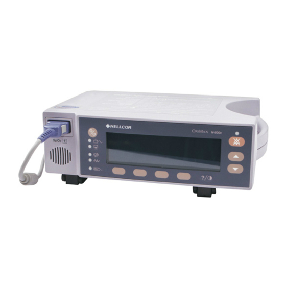
Introduction Overview This manual contains information for servicing the Nellcor O N-600x pulse oximeter. Only qualified service personnel should service this product. Before servicing the monitor, please read the O N-600x Operator's Manual carefully for safe operation. Monitor Description The N-600x monitor is intended for the continuous non-invasive monitoring of functional oxygen saturation of arterial hemoglobin ( ) and pulse rate. -
Page 11: Front Panel
Introduction Front Panel 12. ADJUST UP Button 1. SpO Sensor Port 2. Low Battery Indicator 13. ADJUST DOWN Button 3. AC Power Indicator 14. Neonate Mode Indicator 4. ON/STANDBY Button 15. HELP/CONTRAST Button 5. Battery Fuel Gauge Indicator 16. Fast Response Mode Indicator 6. -
Page 12: Rear Panel
Introduction Rear Panel Type BF N-600x MADE IN IRELAND TYCO HEALTHCARE GROUP LP T 0.50A 250V NELLCOR PURITAN BENNETT INCORPORATED PLEASANTON, CA USA 94588 AUTHORIZED REPRESENTATIVE: TYCO HEALTHCARE UK LTD GOSPORT PO13 0AS, UK CISPR 11 Group 1 Class B... - Page 13 Introduction (Main Menu) LIMITS (Limits Menu) SELECT ADULT EXIT (to Main menu) TREND (Trend Menu) MON (Monitor Menu) VIEW (Monitor Trend View Menu) DUAL SPO2 PULSE NEXT (History/Amplitude Menu) HIST (Delete/Print2 Menu) DELETE (delete Trends) “DELETE TRENDS” YES (return to Main menu) NO (back to Delete/Print menu) PRINT BACK (back to Hist/Amp menu)
- Page 14 Introduction PRINT BACK (back to Sensor menu) TABLE (Table Menu) ^ (show previous table, only available when there is a previous graph; bottom/top line repeats in new table) v (show next table, only available when there is a next graph; bottom/top line repeats in new table) PRINT BACK (back to Sensor menu)
- Page 15 Introduction SELECT (press select to toggle through hours, minutes, seconds, month, day, year; use up/down buttons to set each selection) BACK (back to Clock/Language menu) EXIT (to Main menu) BACK (back to Clock/Language menu) EXIT (to Main menu) LANG (Language Setup Menu) (use up/down buttons to toggle though languages) BACK (back to Clock/Language menu) NEXT (Communication/Nurse Call Menu)
-
Page 16: Related Documents
Refer to the O N-600x Operator's Manual. To utilize the various Nellcor approved O sensors used with the monitor, refer to the individual O Sensor's Directions for Use (DFU). -
Page 17: Routine Maintenance
Routine Maintenance R o u t i n e M a i n t e n a n c e Cleaning the Monitor WARNING: Do not spray, pour, or spill any liquid on the N-600x, its accessories, connectors, switches, or openings in the chassis as this may damage the pulse oximeter. -
Page 18: Periodic Safety Checks
To perform a periodic safety check: 1. Inspect the equipment for mechanical and functional damage. 2. Inspect safety labels for legibility. 3. Contact Nellcor’s Technical Services Department, 1.800.635.5267, or your local Nellcor representative if the labels are damaged. Functional Checks If the monitor has been visibly damaged or subjected to mechanical shock (for example, if dropped), immediately perform the performance tests. -
Page 19: Battery Operation
Routine Maintenance Battery Operation The N-600x has an internal battery that can be used to power the monitor during transport or when AC power is not available. A new, fully-charged battery provides at least seven hours of monitoring time under the following conditions: •... - Page 20 Routine Maintenance When all of the following conditions are present for 15 minutes, the N-600x automatically shuts down: • Monitor is running on battery power • No buttons have been pressed • No pulse has been detected (for example, when a patient is not connected to the O sensor or the O sensor is disconnected...
-
Page 21: Performance Verification
Safety Analyzer Must meet current AAMI ESI/1993 & IEC 60601-1/1998 specifications Pulse Oximetry Cable DOC-10 cable Data Interface Cable EIA-232 cable (optional) Stop Watch Manual or electronic Nellcor model SRC-MAX Tester Provides testing for DigiCal compatible Monitors N-600x Service Manual... -
Page 22: Performance Tests
The battery charge procedure should be performed before monitor repairs when possible. Note: This section uses Nellcor factory defaults. If your institution has custom defaults, those values are displayed. Factory defaults can be restored (see Reset Softkey on page 53). - Page 23 Within ten seconds, all LEDs, pixels and the backlight are illuminated. • The indicators remain lit for two seconds. • The LCD display shows NELLCOR and the software version of the N-600x. Note: The software version displayed in the example below is x.x.x.x. ®...
- Page 24 Performance Verification PLETH Display BLIP Display N-600x %SP02 LIMITS TREND LIGHT SETUP REAL-TIME TREND Display N-600x 30 MIN SPO2 %SP02 %SP02 LIMITS LIMITS TREND TREND SETUP SETUP LIGHT LIGHT...
- Page 25 Performance Verification Power-On Defaults and Alarm Range Limits Note: When observing or changing alarm limits, a time-out is in effect (approximately ten seconds). If no action is taken within the time-out, the monitor automatically returns to the monitoring display. Note: The descriptions below are based on the assumption that the Pleth view is selected.
- Page 26 Performance Verification 5. Press the SELECT softkey. Verify the monitor emits a single beep and the %SpO Lower Alarm Limit of “85” (or your institutional default setting) is selected. N-600x ADULT LIMITS %SP02 %SPO2 UPPER LOWER SAT-S SELECT ADULT EXIT 6.
- Page 27 Performance Verification 12. Press the SELECT softkey four consecutive times. Verify the selected Pulse Rate Lower Alarm Limit display indicates an alarm limit of “40.” N-600x ADULT LIMITS %SP02 %SPO2 UPPER LOWER SAT-S SELECT ADULT EXIT 13. Press and hold the ADJUST DOWN button. Verify the selected Pulse Rate Lower Alarm Limit display decreases to a minimum of “30.”...
-
Page 28: Operational Setup
Performance Verification 21. Ensure the selected %SpO Lower Alarm Limit display indicates an alarm limit of “85.” 22. Confirm the SatSeconds SAT-S alarm is OFF. 23. Ensure the Pulse Rate Upper Alarm Limit display is selected and indicates an alarm limit of “170.” 24. - Page 29 Performance Verification Alarms and Alarm Silence Sensor Port N-600x %SP02 LIMITS TREND SETUP LIGHT To adjust the alarms and alarm silence options: 1. Connect the DOC-10 pulse oximetry cable to the monitor’s SpO sensor port. 2. Connect the DS-100A O sensor to the DOC-10 cable and your finger.
- Page 30 Performance Verification 11. Confirm the following monitor results: • The Plethysmograph waveform tracks the pulse rate. • The Pulse Tone is audible. • The %SpO and pulse rate are flashing in the %SpO and BPM displays. • The Audible Alarm sounds, indicating both parameters have violated the alarm limits.
- Page 31 Performance Verification 19. Wait approximately three minutes. 20. Verify the monitor’s alarm does not return. After three minutes, the monitor’s alarm silence reminder sounds three times, at approximately three minute intervals. Alarm Volume Control After adjusting the alarm volume, perform the following alarm volume test procedure.
- Page 32 Nurse Call Data Port Connector Type BF N-600x MADE IN IRELAND TYCO HEALTHCARE GROUP LP NELLCOR PURITAN BENNETT INCORPORATED T 0.50A 250V PLEASANTON, CA USA 94588 AUTHORIZED REPRESENTATIVE: TYCO HEALTHCARE UK LTD GOSPORT PO13 0AS, UK CISPR 11 Group 1...
- Page 33 Using the Analog Output Data Port Connector Type BF N-600x MADE IN IRELAND TYCO HEALTHCARE GROUP LP NELLCOR PURITAN BENNETT INCORPORATED T 0.50A 250V PLEASANTON, CA USA 94588 AUTHORIZED REPRESENTATIVE: TYCO HEALTHCARE UK LTD GOSPORT PO13 0AS, UK CISPR 11...
- Page 34 Performance Verification 4. Press ANALOG and then the 1 VOLT softkey. 5. Confirm the monitor’s output voltage is +1.0 ± 0.025 VDC, verifying the analog SpO function. 6. Leave the negative lead connected to pin 10 and verify 1.0 ± 0.025 VDC on pins 13 and 14, verifying the monitor’s BPM and Pleth functions.
-
Page 35: General Operation
Operation with a Live Subject LED Excitation Test The LED Excitation Test utilizes normal system components to test circuit operation. A Nellcor O oxygen sensor, model MAX-A, is used to examine LED intensity control. The red LED is used to verify intensity modulation caused by the LED intensity control circuit. - Page 36 Performance Verification To test the circuit operation: 1. Connect the monitor to an AC power source. 2. Connect a DOC-10 pulse oximetry cable to the monitor SpO sensor port. 3. Connect a MAX-A O sensor to the O sensor-input cable. 4.
- Page 37 1. Ensure the monitor is connected to an AC power source. 2. Connect a DOC-10 pulse oximetry cable to the monitor SpO sensor port. 3. Connect a Nellcor O MAX-A oxygen O sensor to the pulse oximetry cable. 4. Clip the MAX-A to the subject as recommended in the O sensor's Directions For Use.
-
Page 38: Pulse Oximetry Functional Tests
Performance Verification Pulse Oximetry Functional Tests These tests utilize the pulse oximetry functional tester (Nellcor model SRC-MAX) to verify the performance of the monitor. See Figure 3. All of the following tests should be completed in sequence. 1. DOC-10 Cable Connector 5. - Page 39 Performance Verification Overview The SRC-MAX functional tester enables qualified technicians to functionally test Nellcor O technology-based pulse oximeters and OEM O technology-based monitors. The following table provides a brief description of each test. Table 2: Tests Descriptions Test No. 1:...
- Page 40 Performance Verification 3. Turn on the monitor by pressing the ON/STANDBY button. After the monitor completes its self-check, the following screen displays: N-600x %SP02 LIMITS TREND SETUP LIGHT • Active audio alarm. • Flashing %SpO indication between 73 and 77 inclusive. •...
- Page 41 Performance Verification 5. Press the SRC-MAX PULSE RATE selection button. The SRC-MAX PULSE RATE 60 LED lights. The monitor BPM decreases and stabilizes to a value between 67 to 73 BPM inclusive. The following screen displays. N-600x %SP02 LIMITS TREND SETUP LIGHT •...
- Page 42 Performance Verification 3. Turn on the monitor by pressing the ON/STANDBY button. After the monitor completes it self-check, the following screen displays: N-600x %SP02 LIMITS TREND SETUP LIGHT • Active audio alarm • Flashing %SpO indication between 73 and 77 inclusive •...
- Page 43 Performance Verification 5. Press the SRC-MAX %SpO selection button. The SRC-MAX %SpO LED lights. The monitor displays three dashes [ - - - ] until stabilizing at a value between 73 and 77 inclusive. The following screen displays: N-600x %SP02 LIMITS TREND SETUP...
- Page 44 Performance Verification 3. Turn on the monitor by pressing the ON/STANDBY button. After the monitor completes the self-check, the following screen displays: N-600x %SP02 LIMITS TREND SETUP LIGHT • Active audio alarm. • Flashing %SpO indication between 73 and 77 inclusive. •...
- Page 45 Performance Verification 5. Press the SRC-MAX PULSE RATE selection button. The SRC-MAX PULSE RATE 200 LED lights. The monitor BPM increases and stabilizes to a value between 197 and 203 inclusive. The following screen displays: N-600x %SP02 LIMITS TREND SETUP LIGHT •...
- Page 46 Performance Verification 7. Press the SRC-MAX %SpO selection button. The SRC-MAX %SpO LED lights. The monitor displays three [ - - - ] dashes until the %SpO stabilizes to a value between 88 and 92 inclusive. The following screen displays: N-600x %SP02 LIMITS...
- Page 47 Performance Verification 9. Press the SRC-MAX MODULATION selection button. The SRC-MAX MODULATION LED lights. The monitor pulse amplitude waveform decreases in amplitude. The following screen displays: N-600x %SP02 LIMITS TREND SETUP LIGHT • Active audio alarm. • Flashing %SpO indication between 73 and 77 inclusive. •...
- Page 48 Performance Verification 3. Turn on the monitor by pressing the ON/STANDBY button. After the monitor completes a self-check, the following screen displays: N-600x %SP02 LIMITS TREND SETUP LIGHT • Active audio alarm. • Flashing %SpO indication between 73 and 77 inclusive. •...
- Page 49 Performance Verification 5. Press the SRC-MAX PULSE RATE selection button. The SRC-MAX PULSE RATE 200 LED lights. The monitor BPM increases and stabilizes at a value between 197 and 203 inclusive. The following screen displays: N-600x %SP02 LIMITS TREND SETUP LIGHT •...
- Page 50 Performance Verification 7. Press the SRC-MAX %SpO selection button. The SRC-MAX %SpO LED lights. The monitor displays three dashes [ - - - ] and stabilizes at a value between 88 and 92 inclusive. The following screen displays: N-600x %SP02 LIMITS TREND SETUP...
- Page 51 Performance Verification 9. Press the SRC-MAX MODULATION selection button. The SRC-MAX MODULATION LED lights. The monitor pulse amplitude waveform increases in amplitude. The following screen displays: N-600x %SP02 LIMITS TREND SETUP LIGHT • Active audio alarm. • Flashing %SpO indication between 73 and 77 inclusive. •...
-
Page 52: Safety Tests
Performance Verification Safety Tests The N-600x safety tests meet the standards of, and are performed in accordance with the IEC 60601-1 (EN 60601-1, Amendment 1, Amendment 2,) and UL 2601-1, for instruments classified as Class 1 and TYPE BF and ANSI/AAMI Standard ES1. -
Page 53: Power-On Settings And Service Functions
Power-On Settings and Service Functions P o w e r - O n S e t t i n g s a n d S e r v i c e F u n c t i o n s Overview This chapter discusses how to reconfigure power-on default values and access the service functions. -
Page 54: Factory Default Settings
Power-On Settings and Service Functions Factory Default Settings Factory default settings are divided into two groups, adult and neonate. Default settings may be changed to institutional default settings; refer to WARNING: Audible alarms should not be silenced if patient safety could be compromised. on page 60. - Page 55 Power-On Settings and Service Functions Table 3: Neonate Alarm Limit Factory Defaults Monitoring Mode Setting Note: Bold entries are different than adult default settings. Allow SatSeconds Trend Display %SpO Trend Scale 2 Hours N-600x Service Manual...
-
Page 56: Adult Default Settings
Power-On Settings and Service Functions Adult Default Settings Table 4: Adult Alarm Limit Factory Defaults Monitoring Mode Setting Note: Bold entries are different than neonate default settings. %SpO Lower Alarm Limit %SpO Upper Alarm Limit 100% Alarm Silence Duration 60 Seconds Alarm Silence Duration Off Setting Disabled Alarm Silence Reminder... -
Page 57: Service Functions
Power-On Settings and Service Functions Service Functions Service functions can be used to select institutional defaults and to access information about the patient or instrument. Only a Nellcor Customer Service Technician should access many of the items available through the service functions. -
Page 58: Exit Softkey
Power-On Settings and Service Functions The following list can be used as a quick reference showing how to reach different softkey functions. Items reached through the PARAM softkey can be accessed during normal operation. Functions provided by the PRINT and NEXT softkeys cannot be accessed when a pulse oximetry cable is connected to the instrument. -
Page 59: Param Softkey Menu
Power-On Settings and Service Functions Param Softkey Menu When the PARAM softkey is pressed, the function of the softkeys changes as shown below. These options can be accessed with the pulse oximetry cable connected to the instrument. N-600x %SP02 RESET SAVE BACK SENSOR... -
Page 60: Print Softkey Menu
Power-On Settings and Service Functions Print Softkey Menu Four printouts including TREND, ERRLOG, INSTAT, and INFO printouts become available when the PRINT softkey is pressed. The appropriate printout can be selected by pressing the corresponding softkey. The PRINT softkey configuration menu is shown below. N-600x %SP02 TREND... - Page 61 Power-On Settings and Service Functions Trend Softkey A Trend printout includes all data recorded for up to 48 hours of monitoring since the last Delete Trends was performed. A new trend point is recorded every four seconds. The figure below is an example of a Trend printout. N-600x VERSION X.X.X.X TREND SpO2 Limit: 30-100%...
- Page 62 Power-On Settings and Service Functions ERRLOG Softkey The ERRLOG softkey should only be used by Nellcor’s Customer Service Engineering. A list of all the errors recorded in memory can be obtained by pressing the ERRLOG softkey. The first line lists the type of instrument producing the printout, software level, type of printout, and the time of the printout.
- Page 63 INFO Softkey The INFO softkey is used by Nellcor’s Customer Service Engineering only. Pressing the INFO softkey produces a single line printout of instrument information as illustrated below. The data presented in the printout from left to...
-
Page 64: Next Softkey Menu
Power-On Settings and Service Functions Next Softkey Menu Additional options can be accessed from the Service Functions Main menu by pressing the NEXT softkey. When NEXT is pressed, the softkeys change to the functions shown below. N-600x %SP02 DOWNLD ALARMS NEXT EXIT DOWNLD Softkey... - Page 65 Power-On Settings and Service Functions SELECT Softkey The SELECT softkey is used to select which function of the audible alarm changes. A box can be cycled between ALLOW OFF and OFF REMINDER. Use the following procedure to select and set the monitor’s ALLOW OFF and OFF REMINDER: 1.
- Page 66 Power-On Settings and Service Functions 5. Use the SELECT softkey to toggle between ALLOW OFF? and OFF REMINDER? 6. Use the ADJUST UP or ADJUST DOWN button to change selected parameter. 7. Press the BACK softkey. The ALLOW OFF softkey provides a choice between enabling or disabling the AUDIBLE ALARM OFF option.
-
Page 67: Setting Institutional Defaults (Sample)
Power-On Settings and Service Functions BATTERY Softkey The BATTRY softkey places the monitor into shelf-mode while the monitor is in storage in order to preserve the life of the battery. This feature will be available in future releases of the O N-600x monitor. - Page 68 Power-On Settings and Service Functions To set institutional defaults: 1. Disconnect the O sensor from monitor. Note: If the O sensor is not disconnected, the only softkeys on the screen will be PARAM and EXIT. 2. Set desired parameters to the institutional values. Refer to the O N-600x Operator’s Manual for parameter values.
-
Page 69: Troubleshooting
Performing Repairs Only qualified service personnel should open the monitor housing, remove and replace components, or make adjustments. If your medical facility does not have qualified service personnel, please contact Nellcor’s Technical Services or your local Nellcor representative. Problem Resolution Problems that may occur with the N-600x are categorized in Table 6. - Page 70 Troubleshooting Table 6: Problem Categories Symptoms Recommended Actions 3. Display/Alarms See Display/Alarms on page 67. • Display does not respond properly. • Alarms and other tones do not sound properly or are generated without apparent cause. 4. Operational See Operational Performance on page 68. Performance •...
-
Page 71: Power
Troubleshooting Power Power problems are related to AC and/or DC. Table 7 lists recommended actions to power problems. Table 7: Power Problems Symptoms Recommended Actions Low Battery indicator • Ensure the N-600x is plugged into an operational lights steadily while AC outlet and the AC indicator is lit. -
Page 72: Buttons
Troubleshooting Table 7: Power Problems Symptoms Recommended Actions Battery does not charge. • Replace battery if it is more than two years old. • If the battery fails to hold a charge, replace the battery as indicated in Battery Replacement on page 88. -
Page 73: Display/Alarms
Troubleshooting Display/Alarms Table 9 lists symptoms of problems relating to non-functioning displays and audible tones or alarms, and recommended actions. If the action requires replacement of a PCB or module, refer to Disassembling the Monitor on page 85. Table 9: Display/Alarms Problems Symptom Recommended Action Display values are... -
Page 74: Operational Performance
Troubleshooting Operational Performance Table 10 lists symptoms of problems relating to operational performance (no error codes displayed) and recommended actions. If the action requires replacement of a PCB or module, refer to Disassembling the Monitor on page 85. Table 10: Operational Performance Problems Symptom Recommended Action The Pulse Amplitude... -
Page 75: Data Port
Troubleshooting Data Port Table 11 lists symptoms of problems relating to the data port and recommended actions. If the action requires replacement of the Main Board PCB, refer to Disassembling the Monitor on page 85. Table 11: Data Port Problems Problem Resolution No printout received. -
Page 76: On-Screen Help
Troubleshooting On-Screen Help The N-600x monitor is equipped with an on-screen help system which enables you to browse and navigate through multiple help topics. Follow the steps outlined below to access and utilize the on-screen help. Accessing Multiple Topics You can access multiple on-screen help topics and select a specific topic to view. Follow the example described below to access the SatSeconds help topic. - Page 77 Troubleshooting window appears. The SatSeconds help topic contains a total of six (6) consecutive help windows. HELP SATSECONDS SatSeconds can reduce alarms reported for mild or brief SpO2 limit violations. Each SpO2 violation can be described. . . (1 / 6) BACK NEXT EXIT...
-
Page 78: Accessing Single Topics
Troubleshooting 8. Press NEXT. HELP SATSECONDS 10, an alarm is reported after 5 seconds. To adjust the SatSeconds limit: Press LIMITS . (6 / 6) BACK EXIT 9. Press BACK to view the previous windows. Continue to press BACK to return to the HELP MAIN window. - Page 79 Troubleshooting 4. Press SHOW. The HELP LIMITS SELECT window appears. HELP LIMITS SELECT Press SELECT to select the limit to be adjusted. Press to set the desired limit value. (1 / 1) BACK EXIT 5. Press BACK. 6. Press ADJUST DOWN to highlight NEO and then press SHOW. The HELP LIMITS NEO window appears.
-
Page 80: Error Codes
Troubleshooting Error Codes An error code is displayed when the monitor detects a non-correctable failure. Table 12 provides a list of error codes for the monitor. When one of the following errors occurs: • the monitor sounds a low priority alarm that cannot be silenced except by power-down •... - Page 81 Troubleshooting Table 12: Error Codes Error Code Description %SpO front end reports warmer error. Front end data not received. 54-128 Reserved for future frond end object errors. 129-171 Unexpected LPS error (LPS recovered from this error). 172-255 Reserved for future front end object errors. %SpO back end reports beginning of packet missing.
- Page 82 Troubleshooting Table 12: Error Codes Error Code Description %SpO back end reports overflow/underflow. %SpO back end reports sensor activation failure. %SpO back end reports sensor write failure. ECG trigger error. Sensor trend not open. Sensor trend already open. Sensor trend data unavailable. All sensor trend data read.
- Page 83 Troubleshooting Table 12: Error Codes Error Code Description External watchdog failure. Power PC watchdog failure. Boot NVROM uninitialized error. Failed CRC check of application code in flash. Failed periodic ram CRC check on application code running in RAM. Memory corruption detected. RTOS Resource unavailable.
- Page 84 Troubleshooting Table 12: Error Codes Error Code Description Oximetry module ROM/Code integrity error. Oximetry module RAM error. Oximetry module reports background self-test failed to complete in the allocated time. Oximetry module reports a state machine is in an unexpected state. Oximetry module reports memory corruption detected.
- Page 85 Troubleshooting Table 12: Error Codes Error Code Description Battery charger error - instance #2. Battery charger error - instance #3. Battery charger error - instance #4. Battery charger error - instance #5. Battery charger error - instance #6. Battery charger error - instance #7. Battery charger error - instance #8.
-
Page 86: Additional Messages
Troubleshooting Additional Messages In addition to the error codes listed in Table 12, the following messages may be encountered: Table 13: Additional Display Messages Message Description Adjust Contrast An attempt to adjust the contrast of the display by Up, Down pressing and holding the HELP/CONTRAST button. -
Page 87: Primary Speaker Failure
Troubleshooting Table 13: Additional Display Messages Message Description sensor has disconnected from the pulse Sensor oximetry cable, the cable has disconnected from the Disconnected monitor, or the sensor/cable wiring is defective. Press the ALARM SILENCE button to silence the alarm. Check the connections. - Page 88 WARNING: If an N-600x reports a primary speaker failure, do not use the monitor longer than necessary to ensure patient safety. Contact a qualified service personnel, your local Nellcor representative, or Nellcor's Technical Services Department for assistance.
-
Page 89: Disassembling The Monitor
Disassembling the Monitor D i s a s s e m b l i n g t h e M o n i t o r Overview The monitor can be disassembled down to all major component parts, including: • PCBs •... -
Page 90: Replacement Level
Disassembling the Monitor Replacement Level The supported replacement level for the N-600x monitor is to the printed circuit board (PCB) and major subassembly level. Once a suspected PCB is isolated, follow the procedures in Disassembling the Monitor on page 85, to replace the PCB with a known good PCB. -
Page 91: Disassembling The Monitor
Disassembling the Monitor Disassembling the Monitor To disassemble the monitor: 1. Turn the monitor off by pressing the ON/STANDBY button. 2. Disconnect the monitor from the AC power source. 3. Set the monitor upside down on a static-free work surface. Caution: Ensure the work surface is clean and free of debris. - Page 92 Disassembling the Monitor 7. Remove the monitor’s four corner screws. Remove the corner screws Figure 5: Removing the Corner Screws Caution: Observe ESD (electrostatic discharge) precautions when disassembling and reassembling the N-600x and when handling any of the components of the N-600x. 8.
- Page 93 Disassembling the Monitor 10. Disconnect the monitor’s power supply harness from J200 on the Main Board PCB. J200 Figure 6: Opening the Monitor Casing N-600x Service Manual...
-
Page 94: Assembling The Monitor
Disassembling the Monitor Assembling the Monitor To assemble the monitor: 1. Connect the monitor’s Power Supply to J200 on the Main Board PCB. 2. Place the monitor’s top enclosure over the bottom case, being careful to align the Display PCB, Power Entry Module, and the fan with the slots in the monitor casing. -
Page 95: Replacing The Battery
Caution: The lead-acid battery is recyclable. Do not dispose of the battery by placing it in the regular trash. Dispose of the battery in accordance with local guidelines or contact Nellcor’s Technical Services department to arrange for disposal. Replacing the Battery To replace the old battery: 1. -
Page 96: Power Entry Module (Pem) Replacement
Disassembling the Monitor 4. Follow the steps outlined in Assembling the Monitor on page 88. 5. Power the monitor on to verify proper operation. Power Entry Module (PEM) Replacement Removing the Power Entry Module To remove the power entry module: 1. -
Page 97: Replacing The Power Entry Module
Disassembling the Monitor Replacing the Power Entry Module To replace the power entry module: 1. Reconnect the three power supply leads as indicated in Table 14 on page 92. 2. Install the PEM in the bottom case with the fuse drawer facing down. A tab in the bottom case holds the PEM in place. -
Page 98: Replacing The Power Supply
Disassembling the Monitor 6. Use a 10mm wrench to disconnect the power supply ground lead from the equipotential terminal shown in Figure 8 on page 90. 7. Remove the seven screws shown in Figure 9 on page 92. 8. Lift the power supply out of the bottom case. Figure 9: Power Supply Replacing the Power Supply To replace the power supply:... -
Page 99: Cooling Fan Replacement
Disassembling the Monitor 2. Place the power supply in the bottom case. Caution: When installing the power supply, tighten the seven screws (4-in lbs maximum). Overtightening could strip out the screw holes in the bottom case, rendering it unusable. 3. Install the seven screws in the power supply and tighten. 4. -
Page 100: Replacing The Cooling Fan
Disassembling the Monitor 4. Lift the cooling fan from the slots in the bottom case. Figure 10: Cooling Fan Replacing the Cooling Fan To replace the cooling fan: 1. Connect the cooling fan wire harness to J1 on the Power Supply PCB. 2. -
Page 101: Display Pcb Replacement
Disassembling the Monitor Display PCB Replacement Removing the Display PCB WARNING: The LCD panel contains toxic chemicals. Do not ingest chemicals from a broken LCD panel. To remove the Display PCB: 1. Turn the monitor off by pressing the ON/STANDBY button. 2. -
Page 102: Replacing The Display Pcb
Disassembling the Monitor 6. Remove and discard the used double-sided tape. Double-sided tape Display PCB Double-sided tape Speaker wires to J9 on the Main Board PCB Display ribbon cable CCFL wires to J4 on the Main Board PCB Display ribbon cable to J7 on Main Board PCB Figure 11: Display PCB Replacing the Display PCB... -
Page 103: Main Board Pcb Replacement
Disassembling the Monitor 5. Connect the CCFL wire harness with two white wires to J4 on the Main Board PCB. 6. Connect the Display PCB ribbon cable to J7 on the Main Board PCB. Install the clip over the J7 connector. 7. -
Page 104: Replacing The Main Board Pcb
Disassembling the Monitor 9. Remove the Main Board PCB from the top case. Figure 12: Main Board PCB Replacing the Main Board PCB Caution: When installing the Main Board PCB, hand-tighten the six screws (4-in lbs maximum). Overtightening could strip out the screw holes in the top case, rendering it unusable. -
Page 105: Alarm Speaker Replacement
Disassembling the Monitor 6. Insert the J200 cable into the Main Board PCB until it locks into place. 7. Connect the speaker cable to J9 on the Main Board PCB. 8. Connect the CCFL wire harness with two white wires to J4 on the Main Board PCB. - Page 106 Disassembling the Monitor 4. Pull the holding clip back from the speaker and lift the speaker out of the top case. Connect speaker wires to J9 connector Holding Clip Figure 13: Alarm Speaker 5. Remove the speaker by gently releasing the retaining tab and sliding the speaker assembly from its mounting.
-
Page 107: Replacing The Alarm Speaker
Disassembling the Monitor Replacing the Alarm Speaker To replace the alarm speaker: Caution: Handle the speaker ONLY by the edges of the metal ring to avoid damage. WARNING: Do not allow other metal objects to come into contact with the speaker;... -
Page 108: Top Case Assembly Replacement
Disassembling the Monitor Top Case Assembly Replacement Removing the Top Case Assembly To remove the top case assembly: 1. Turn the monitor off by pressing the ON/STANDBY button. 2. Disconnect the monitor from the AC power source and follow the steps outlined in Disassembling the Monitor on page 85. -
Page 109: Spare Parts
Ordering Replacement Parts Nellcor's Technical Services provides technical assistance information and replacement parts. Contact Nellcor or your local Nellcor representative to obtain replacement parts. Refer to parts by the part names and part numbers. A listing of the spare parts and accessories for the N-600x is on the Internet at: http://www.nellcor.com... -
Page 110: Spare Parts List
Spare Parts Spare Parts List The figure below shows the N-600x expanded view. See the Spare Parts List on page 105 for descriptions and part numbers. Figure 14: Exploded View... - Page 111 Spare Parts Table 15: Spare Parts List Item Description Part Number Top Enclosure with Membrane Switch 10009087 Main Board or Main PCB SP10014868 Battery Bracket 035307 Battery 640119 Display PCB SP10006091 Fuse Drawer 691500 Fuses 691032 Power Entry Module 10004406 Cooling Fan 10003713 Power Supply Board or LPS PCB...
- Page 112 Spare Parts...
-
Page 113: Packing For Shipment
Services Department or your local Nellcor representative for shipping instructions, including a Returned Goods Authorization (RGA) number. Unless otherwise instructed by Nellcor's Technical Services, it is not necessary to return the O sensor or any other accessory items with the monitor, unless otherwise instructed by the Nellcor representative. -
Page 114: Repacking The Monitor Using The Original Carton
Packing for Shipment Repacking the Monitor Using the Original Carton To repack the monitor using the original carton: If available, use the original carton and packing materials as shown in Figure 15 on page 108. Pack the monitor as follows: 1. -
Page 115: Repacking The Monitor Using A Generic Carton
Packing for Shipment Repacking the Monitor Using a Generic Carton To repack the monitor using a generic carton: If the original carton is not available, use the following procedure to pack the monitor: 1. Place the monitor in a plastic bag. 2. - Page 116 Packing for Shipment...
-
Page 117: Specifications
Specifications S p e c i f i c a t i o n s Performance Measurement Range %SpO 1% to 100% Pulse Rate 20 to 250 beats per minute (bpm) Perfusion Range 0.03% to 20% Accuracy LoSAT™ 60% to 80% 70% to 100% MAX-A, MAX-AL ±... -
Page 118: Electrical Requirements
Specifications Accuracy For a complete listing of SpO accuracy across the full line of available Nellcor sensors, see the Sensor Accuracy Grid online at: http://www.nellcor.com, or contact 1-800-NELLCOR. Subjects used to validate SpO measurement accuracies were healthy and recruited from the local population. - Page 119 Complies With 91/157/EEC Sensors Wavelength and Nellcor pulse oximetry sensors contain LEDs that emit red light Power at a wavelength of approximately 660 nm and infrared light at a wavelength of approximately 900 nm. The total optical output power of the sensor LEDs is less than 15 mW. This information may be useful to clinicians, such as those performing photodynamic therapy.
-
Page 120: Environmental Conditions
Specifications Conditions Environmental Operating Temperature 5 ºC to 40 ºC (41 ºF to 104 ºF) Altitude -390 m to 3,012 m (-1,254 ft. to 9,882 ft.) Atmospheric Pressure 70 kPa to 106 kPa (20.6 in. Hg to 31.3 in. Hg) Relative Humidity 15% to 95% non-condensing to be compliant with IEC 60601-1,... -
Page 121: Physical Characteristics
Specifications Sensor Power Dissipation Sensor Dissipation MAX-I 52.5 mW MAX-P 52.5 mW MAX-A 52.5 mW MAX-AL 52.5 mW MAX-R 52.5 mW Durasensor DS-100A 52.5 mW ® 52.5 mW OxiCliq OxiCliq N 52.5 mW OxiCliq I 52.5 mW OxiCliq A 52.5 mW ®... - Page 122 Specifications Item Compliant With Type of protection Class I (on AC power) Internally powered (on battery power) Degree of protection Type BF - Applied part Mode of operation Continuous N-600x resistant to liquid ingress IEC 60601-1, sub-clause 44.6 for class IPX1 Drip-Proof equipment Degree of Safety in presence of a UL 60601-1, sub-clause 5.5, Not suitable...
-
Page 123: Manufacturer's Declaration
Specifications Declaration Manufacturer’s WARNING: The use of accessories, O sensors, and cables other than those specified may result in increased emission and/or decreased immunity of the N-600x pulse oximeter. Table 16: Electromagnetic Emissions The N-600x is suitable for use in the specified electromagnetic environment. The customer and/or user of the N-600x should assure that it is used in an electromagnetic environment as described below: Electromagnetic Environment... - Page 124 Specifications Table 17: Electromagnetic Immunity The N-600x is suitable for use in the specified electromagnetic environment. The customer and/or user of the N-600x should assure that it is used in an electromagnetic environment as described below. Electromagnetic Immunity IEC 60601-1-2 Compliance Environment Test...
- Page 125 Specifications Table 17: Electromagnetic Immunity The N-600x is suitable for use in the specified electromagnetic environment. The customer and/or user of the N-600x should assure that it is used in an electromagnetic environment as described below. Electromagnetic Immunity IEC 60601-1-2 Compliance Environment Test...
- Page 126 Specifications Table 18: Electromagnetic Immunity, RF Portable Equipment The N-600x is suitable for use in the specified electromagnetic environment. The customer and/or user of the N-600x should assure that it is used in an electromagnetic environment as described below: Electromagnetic Immunity IEC 60601-1-2 Compliance...
- Page 127 Specifications Table 19: Recommended Separation Distances Recommended Separation Distances between Portable and Mobile RF Communications Equipment and the N-600x (IEC 60601-1-2) Frequency of 150 kHz to 80 MHz to 800 MHz to Transmitter 80 MHz 800 MHz 2.5 GHz Equation d = 1.2 d = 1.2 d = 2.3...
- Page 128 Specifications Table 20: Cables Cables and Maximum Complies With Sensors Length DOC-10 pulse 10.0 ft. (3 m) • RF emissions, CISPR 11, oximetry cable Class B/Group 1 Software 10.0 ft. (3 m) • Harmonic emissions, IEC 61000-3-2 download cable, RS-232 serial, 15 to 9 pin “D”...
- Page 129 Specifications Table 20: Cables Cables and Maximum Complies With Sensors Length 3.0 ft. (0.9 m) • RF emissions, CISPR 11, Durasensor Class B/Group 1 sensor • Harmonic emissions, IEC 61000-3-2 DS-100A • Voltage fluctuations/flicker emission, IEC 61000-3-3 • Electrostatic discharge (ESD), IEC 61000-4-2 •...
-
Page 130: Safety Tests
Specifications Safety Tests Ground Integrity 100 milliohms or less Earth Leakage Current The following table displays the maximum earth leakage current allowed: Neutral AC Polarity Line Cord EN/IEC 60601-1 UL 60601-1 Cord 500 µA 300 µA Normal Closed Closed 500 µA 300 µA Reversed Closed... -
Page 131: Patient Applied Risk Current
Specifications Patient Applied Risk Current The following table displays the maximum patient applied risk current for a BF type applied part. Neutral Power Line IEC 60601-1 AC Line Polarity Line Ground Cable UL 60601-1 Normal Closed Closed 100 µA 500 µA Normal Open Closed... - Page 132 Specifications...
-
Page 133: Data Port Interface Protocol
Overview When connected to the data port on the back of the N-600x, printouts can be obtained or patient data can be communicated to a Nellcor Oxinet II monitoring system, Nellcor Oxinet III monitoring system, Nellcor Intouch Remote Oximetry Notification System or personal computer. Analog signals representing %SpO pulse rate, and pulse amplitude are also provided by the data port. -
Page 134: Communication Baud Rate
Data Port Interface Protocol NEXT COMM SELECT BAUD 2400 9600 19200 PROTOCOL ASCII OXINET CLINICAL GRAPH PHILIPS (Philips monitors) SPACELBS (Spacelabs monitors) MARQ (GE Marquette monitors) DATEX (Datex-Ohmeda AS/3 monitor) BACK (back to Setup menu) EXIT (back to Main menu) NCALL (Nurse Call) NORM + NORM -... -
Page 135: Communication Protocol
The selections are: • ASCII used for printouts • OXINET to enable communication with OXINET II • CLINICAL intended for Nellcor use only • GRAPH for graphic printouts • PHILIPS interfaces the N-600x with a Philips monitor •... - Page 136 Data Port Interface Protocol To change the communication protocol: 1. Turn on the monitor by pressing the ON/STANDBY button. 2. Press the SETUP softkey. 3. Press the NEXT softkey twice. 4. Press the COMM softkey. 5. Press the SELECT softkey. 6.
-
Page 137: Language Selection
Data Port Interface Protocol Language Selection Eleven (11) languages can be viewed on the screen and sent to the printer. The languages are: ENGLISH DANSK (Danish) DEUTSCH (German) ESPAÑOL (Spanish) FRANCAIS (French) ITALIANO (Italian) NEDERLANDS (Dutch) NORSK (Norwegian) PORTUG (Portuguese) SUOMI (Finnish) SVERIGE (Swedish) To change the displayed language setting:... -
Page 138: Nurse Call Setup
Data Port Interface Protocol Nurse Call Setup The voltage polarity for the Nurse Call, available at pins 11 and 5, can be selected through the softkeys. NORM + sets the voltage to +5 VDC to +12 VDC and NORM - sets the voltage to -5 VDC to -12 VDC when there is no audible alarm. When an audible alarm occurs, these voltages switch polarity. -
Page 139: Analog Calibration Setup
(A05 option) to interface with the N-600x pulse oximeter. The RS-232 hardware interface cable has a DB-15 connector for the N-600x and the applicable connector for the Philips monitor. The Nellcor cable part number 902256 is recommended for this interface. -
Page 140: Spacelabs Communications
N-600x pulse oximeter. The interface module comes with an interface cable, GE Marquette part number 417961-033, that connects to the Nellcor interface cable. The RS-232 hardwire interface cable has a DB-15 connector for the monitor and the applicable connector for the Marquette Octanet interface module cable. -
Page 141: Datex-Ohmeda As/3 Communications
Datex-Ohmeda AS/3 Communications The Datex-Ohmeda AS/3 monitor must be configured for communications with the Nellcor N-200 monitor in order to communicate with the N-600x monitor. Refer to the AS/3 Operator's Manual for instructions on configuring the AS/3 monitor. The N-600x sends SpO , pulse rate, and alarm status data to the Datex AS3 monitor. -
Page 142: Connecting To The Data Port
Data Port Interface Protocol Connecting to the Data Port Data is transmitted in the RS-232 format (pins 2, 3, and 5) or RS-422 (pins 1, 4, 9, and 12). RS-232 data can be transmitted a maximum of 25 feet, RS-422 data up to 4000 feet. -
Page 143: Communicating With A Computer
Dump Instrument Info (Option 1) Option 1 allows the Instrument Info to be printed, displayed on the computer screen and intended for Nellcor’s personnel. Instrument Info is a single line of data, which includes software version, CRC number, and total operating time. -
Page 144: Set Date And Time (Option 2)
This option is intended for Nellcor’s field service personnel. Exit Interactive Mode (Option 5) Option 5 closes the interactive mode and returns the data port to normal operation. -
Page 145: Using Data On The Computer
Data Port Interface Protocol Using Data on the Computer Data displayed on the computer screen can be captured for use in a word processing spreadsheet. To access data using a computer: 1. Open a terminal program, such as Hyper Terminal. 2. - Page 146 Data Port Interface Protocol Note: If the data output stops transmitting, turn the power off and back on again, or, if the monitor is connected to a computer, send an XON (Ctrl-q) to resume transmission. N-600x VERSION 4.0.0.0 CRC: XXXX SpO2 Limit: 85-100% PR Limit: 40-170BPM ADULT 0SAT-S...
-
Page 147: Column Heading
Data Port Interface Protocol Column Heading The first two lines of the chart are the column headings shown below. Every 25th line a column heading is printed. A column heading is also printed when a value of the column heading is changed. There are three column headings shown in Figure 17. -
Page 148: Patient Data And Operating Status
Data Port Interface Protocol Monitor Status N-600x VERSION X.X.X.X CRC: XXXX SpO2 Limit: 70-100% PR Limit: 60-160BPM ADULT 0SAT-S SPO2 RESP MODE: NORMAL TIME %SpO2 Status The monitor status, ADULT or NEO (Neonate), is displayed on the second line of the heading. - Page 149 Data Port Interface Protocol Patient Data N-600x VERSION X.X.X.X. CRC: XXXX SpO2 Limit: 70-100% PR Limit: 60-160BPM ADULT 0SAT-S SPO2 RESP MODE: NORMAL TIME %SpO2 Status 01-JAN-06 14:00:05 *190 Patient data and the operating status of the unit are highlighted in the display above.
-
Page 150: Trend Data Printout (Ascii Mode)
Data Port Interface Protocol Table 22: Operating Status Codes Code Meaning Pulse Search Sensor Disconnect Saturation Upper Limit Alarm Saturation Lower Limit Alarm - - - No Data Available Alarm Parameter Being Violated Note: A Sensor Disconnect can cause three dashes [ - - - ] to display in the patient data section of the printout. -
Page 151: Trend Printout (Graph Mode)
Data Port Interface Protocol Trend Printout (Graph Mode) The Graph mode (Figure 19 and Figure 20) disables all printout functions except trend data. Trend printouts are graphical if connected to a serial printer that supports Epson ESC protocol. To print in the Graph mode, the monitor protocol must be changed to Graph. See Communication Protocol on page 129. -
Page 152: Analog Output
Data Port Interface Protocol alarm and no alarm conditions, and for instrument off. Table 24 defines the ratings of the Nurse Call Relay. Table 23: Nurse Call Relay Pin States No Alarm or Audible Instrument Alarm Alarm Silenced 7 N.O. Open Closed Closed... -
Page 153: Technical Discussion
Technical Discussion T e c h n i c a l D i s c u s s i o n Oximetry Overview The N-600x uses pulse oximetry to measure functional oxygen saturation in the blood. Pulse oximetry works by applying an O sensor to a pulsating arteriolar vascular bed, such as a finger or toe. -
Page 154: Functional Versus Fractional Saturation
Technical Discussion Functional versus Fractional Saturation The pulse oximeter measures functional saturation -- oxygenated hemoglobin expressed as a percentage of the hemoglobin that can transport oxygen. It does not detect significant amounts of dysfunctional hemoglobin, such as carboxyhemoglobin or methemoglobin. In contrast, hemoximeters such as the IL482 report fractional saturation -- oxygenated hemoglobin expressed as a percentage of all measured hemoglobin, including measured dysfunctional hemoglobins. -
Page 155: Satseconds Alarm Management
O sensor. Consult the accuracy card included with the pulse oximeter for specific accuracy information for the N-600x with different Nellcor approved O sensors. N-600x Service Manual... -
Page 156: Block Diagram Theory
Technical Discussion The N-600x uses the information in the O sensor to tailor troubleshooting messages for the clinician. The O sensor contains coding telling the pulse oximeter the type of O sensor being used. When deciding which messages to display, the pulse oximeter determines the O sensor type and recommended patient site for each model. - Page 157 Technical Discussion The N-600x contains the Motorola MPC823e PowerPC (823e) microprocessor. As shown in the block diagram above, the 823e provides the bulk of the functionality in the instrument, acting as the “master” controller, while NELL-1A Oximetry Module handles the pulse oximetry functions and the Linear Power Supply (LPS) board microcontroller handles the AC/Battery power management tasks, Communications between the N-600x board and the Nell-1A module takes place over an asynchronous isolated bidirectional serial link.
- Page 158 Technical Discussion and shuts off the unit power supply if the battery voltage becomes too low to support N-600x functionality. The Patient Isolated power supply for the N-600x is an isolated switcher which generates +3.3, +5, and +12 volts. The patient is connected to the N-600x via an O sensor and pulse oximetry cable.
- Page 159 Technical Discussion Figure 23: LPS Board Schematic Diagram (Sheet 1 of 1) N-600x Service Manual...
- Page 160 Technical Discussion...
- Page 161 Technical Discussion Figure 24: Main PCB Schematic Diagram (Sheet 2 of 11) N-600x Service Manual...
- Page 162 Technical Discussion...
- Page 163 Technical Discussion Figure 25: Main PCB Schematic Diagram (Sheet 2 of 11) N-600x Service Manual...
- Page 164 Technical Discussion...
- Page 165 Technical Discussion Figure 26: Main PCB Schematic Diagram (Sheet 3 of 11) N-600x Service Manual...
- Page 166 Technical Discussion...
- Page 167 Technical Discussion Figure 27: Main PCB Schematic Diagram (Sheet 4 of 11) N-600x Service Manual...
- Page 168 Technical Discussion...
- Page 169 Technical Discussion Figure 28: Main PCB Schematic Diagram (Sheet 5 of 11) N-600x Service Manual...
- Page 170 Technical Discussion...
- Page 171 Technical Discussion Figure 29: Main PCB Schematic Diagram (Sheet 6 of 11) N-600x Service Manual...
- Page 172 Technical Discussion...
- Page 173 Technical Discussion Figure 30: Main PCB Schematic Diagram (Sheet 7 of 11) N-600x Service Manual...
- Page 174 Technical Discussion...
- Page 175 Technical Discussion Figure 31: Main PCB Schematic Diagram (Sheet 8 of 11) N-600x Service Manual...
- Page 176 Technical Discussion...
- Page 177 Technical Discussion Figure 32: Main PCB Schematic Diagram (Sheet 9 of 11) N-600x Service Manual...
- Page 178 Technical Discussion...
- Page 179 Technical Discussion Figure 33: Main PCB Schematic Diagram (Sheet 10 of 11) N-600x Service Manual...
- Page 180 Technical Discussion...
- Page 181 Technical Discussion Figure 34: Main PCB Schematic Diagram (Sheet 11 of 11) N-600x Service Manual...
- Page 182 Technical Discussion...
-
Page 183: Index
Index I n d e x Accessories on Internet Danish Adjust Contrast Up, Down DANSK Adjusting the Power-On Settings Data Port Interface Protocal Adult Default Settings Data Port Pin Layout Alarm Management, SatSeconds Data Port Pin Outs Alarm Off Data Port Problems Alarm Range Limits Data Port, Connecting To Alarm Silence... - Page 184 Index Finnish Accuracy Tolerance 111 Fractional Saturation Measurement Range 111 French Monitor Assembly Front Panel Monitor Description Functional Checks Monitor Disassembly Functional Saturation Fuse Replacement Neonate Default Settings 52, 58 Next Softkey GE Marquette Communications Norwegian German 26, 145 Nurse Call Graph Mode Nurse Call Relay Pin States Ground Integrity Specification...
- Page 185 Index Power-On Settings and Service Functions Service Functions, Accessing Power-Up Performance Setting 80, 81 Primary Speaker Failure Date and Time 138 Print Softkey Setting Institutional Defaults Printout, Real-Time Settings Lost Problem Categories Pulse Tone Volume Control Softkey Menu Software Version SpaceLabs Communications Spanish Reading Trends...
- Page 186 Index Test No. 3 Modulation Level 37 Test No. 4 Light 41 Transport Altitude 114 Relative Humidity 114 Temperature 114 Trend Data Printout (ASCII Mode) Trend Printout (Graph Mode) Trend Softkey Troubleshooting Guide Unit Will Shut Down If AC Power Is Lost Using Data on the PC Warnings Who Should Perform Repairs...
- Page 188 Tyco Healthcare Group LP Nellcor Puritan Bennett Division 4280 Hacienda Drive Pleasanton, CA 94588 U.S.A. Telephone 1.800.635.5267 Authorized Representative Tyco Healthcare UK LTD 154 Fareham Road Gosport PO13 0AS, U.K. © 2007 Nellcor Puritan Bennett LLC All rights reserved. Rx ONLY 10006679B-0507...
Need help?
Do you have a question about the OxiMax N-600x and is the answer not in the manual?
Questions and answers