Table of Contents
Advertisement
Quick Links
SERVICE MANUAL
NPB-40
Handheld Pulse Oximeter
Caution: Federal law (U.S.) restricts this device to sale by or on the order of a physician.
To contact Nellcor Puritan Bennett's representative: In the United States, call 1-800-635-5267 or
012 3
925-463-4000; outside of the United States, call your local Nellcor Puritan Bennett representative.
© 2001 Nellcor Puritan Bennett, Inc. All rights reserved.
036048D-0601
Advertisement
Table of Contents
Troubleshooting

Related Manuals for Nellcor NPB-40


Summary of Contents for Nellcor NPB-40
- Page 1 Handheld Pulse Oximeter Caution: Federal law (U.S.) restricts this device to sale by or on the order of a physician. To contact Nellcor Puritan Bennett’s representative: In the United States, call 1-800-635-5267 or 012 3 925-463-4000; outside of the United States, call your local Nellcor Puritan Bennett representative.
- Page 2 Bennett representative. Notice: Purchase of this instrument confers no express or implied license under any Nellcor Puritan Bennett patent to use the instrument with any sensor that is not manufactured or licensed by Nellcor Puritan Bennett. Oxisensor II is a trademark of Nellcor Puritan Bennett, Inc.
-
Page 3: Table Of Contents
Introduction..................System Disassembly and Reassembly .......... Section 6: Spare Parts.................. Introduction..................Section 7: Packing for Shipment..............General Instructions................ Packing NPB-40 in Original Carton ..........Packing in a Different Carton ............Section 8: Specifications ................Performance ................... Electrical ..................Environmental................. Physical .................. - Page 4 LIST OF FIGURES NPB-40 Handheld Pulse Oximeter ..........NPB-40 Front Panel............... NPB-40 Battery Installation ............NPB-40 Self-Test Front Panel Display .......... Printer Interface Setup..............Typical Average Data Print Out ............. Typical Data Print Out ..............Typical Error Code Display ............
-
Page 5: Section 1: Introduction
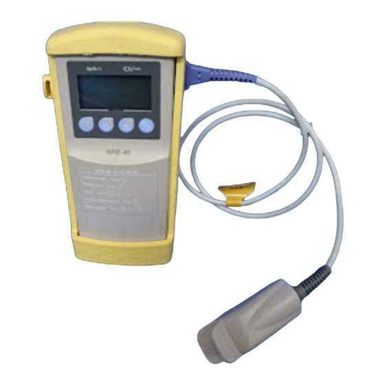
Puritan Bennett. The NPB-40 handheld pulse oximeter is illustrated in Figure 1-1. Figure 1-1: NPB-40 Handheld Pulse Oximeter The NPB-40 is operated using a four-key keypad and an LCD display on the front panel as shown in Figure 1-2. Refer to the NPB-40 operator’s manual for complete operating instructions. - Page 6 Pulse Amplitude indicator Pulse Rate display Pulse Search display Low Battery indicator Sensor disconnect indicator Power On/Off key Display Light/Beep On/Off key Store Data/Print key Shift key Store Data icon Shift icon Print icon SpO2% display Figure 1-2: NPB-40 Front Panel...
-
Page 7: Section 2: Routine Maintenance
NPB-40 batteries should be replaced whenever a low battery indication is observed on the unit. Remove the batteries if you will be storing the NPB-40 for longer than one month. Refer Figure 2-1 for replacing the batteries. -
Page 8: Battery Disposal
Warning: Never dispose of NPB-40 batteries by burning. The batteries could explode in fire and cause serious personal injury. CLEANING Caution: Do not immerse the NPB-40 or accessories in liquid or use caustic or abrasive cleaners. To clean the NPB-40, dampen a soft cloth with a commercial nonabrasive... -
Page 9: Section 3: Performance Verification
SECTION 3: PERFORMANCE VERIFICATION Performance Verification PERFORMANCE VERIFICATION The performance of the NPB-40 can be verified using the following procedure. Before performing this procedure, the NPB-40 must have fresh batteries installed. If any of the required observations cannot be obtained, do not return the NPB-40 to service before referring to Section 4, Troubleshooting. - Page 10 LIGHT HIGH 2 MODULATION Wait 30 seconds and verify that the NPB-40 is displaying a pulse rate of 38 (±3 bpm), that the pulse amplitude indicator is displaying properly, that the SpO % indicator is displaying 81 (±2 %), that a pulse beep can be heard, and that the PULSE SEARCH indicator is off.
- Page 11 LOCAL/REMOTE/RCAL LOCAL On the NPB-40, verify that the PULSE SEARCH indicator illuminates momentarily and verify that the NPB-40 is displaying a pulse rate of 201 (±3 bpm), that the pulse amplitude indicator is displaying properly, that the SpO % indicator is displaying 79 to 83, that a pulse beep can be heard, and that the PULSE SEARCH indicator is off.
- Page 12 Figure 3-3. Figure 3-3: Typical Average Data Print Out With the SRC-2 connected to the NPB-40 and still set up as in step 18, press only the Store Data/Print key on the front panel keypad and verify that the LCD display indicates “1-Id”...
- Page 13 Section 3: Performance Verification Figure 3-4: Typical Data Print Out Press the On/Off key on the front panel keypad. Verify that the NPB-40 shuts off.
- Page 14 (This page intentionally left blank)
-
Page 15: Section 4: Troubleshooting
WHO SHOULD PERFORM REPAIRS Only qualified service personnel should remove and replace components of the NPB-40. Repairs to the NPB-40 are limited to the repair level identified in Paragraph 4.3, “Repair Level Supported.” If your facility does not have qualified service personnel, contact the Nellcor Puritan Bennett Technical Services Department or your local Nellcor Puritan Bennett representative. -
Page 16: Troubleshooting Guide
If an error code is shown on the front panel LCD display, as shown in Figure 4-1, turn the NPB-40 off and back on again. If the error code still persists, refer to Table 4-2 for the indicated failure and corrective action. - Page 17 On/Off key is pressed. (continued) The front panel Open the NPB-40, disconnect keypad is defective. the case top from J3 on the CPU PCB and connect an ohmmeter between the flex circuit conductor for J3, pin 5 and the conductor for J3, pin 3.
- Page 18 The holes for the Clear the holes for the beeper on beeper on the back of the back of the NPB-40. the NPB-40 are blocked. The external output Replace the CPU PCB with a port on the CPU PCB known good PCB.
- Page 19 Replace the CPU PCB with a CPU PCB has failed. known good PCB. The printer is Attempt to print using another defective. known good NPB-40. If the printer still does not print, troubleshoot the printer Table 4-2: NPB-40 Error Codes Error Code Failure Indicated...
- Page 20 (This page intentionally left blank)
-
Page 21: Section 5: Disassembly Guide
When you receive these spare parts, please fill out and return the business reply card. The only tool you will need to disassemble or reassemble the NPB-40 is a Number 1 (medium) Phillips-head screwdriver. Caution: Observe ESD (electrostatic discharge) precautions when disassembling and reassembling the NPB-40 and when handling any of the components of the NPB-40. - Page 22 Remove screws Figure 5-1: Opening the NPB-40 Case While holding the case together, turn the NPB-40 over with the front panel up and the bottom of the unit closest to you. Separate the case top from the bottom case on the right side of the unit and rotate the case top to the left as shown in Figure 5-2.
- Page 23 Figure 5-4: Separating LCD PCB from CPU PCB Note: When reassembling the NPB-40, be sure to align all 20 pins of both J1 and J2 on the CPU PCB with all 20 sockets of J1 and J2 on the LCD PCB before pressing the two PCBs together.
- Page 24 (This page intentionally left blank)
-
Page 25: Section 6: Spare Parts
In December, 1997, the external plastic parts of the NPB-40 were modified. Plastic parts made after that date are incompatible with parts made before that time. - Page 26 Section 6: Spare Parts Figure 6-1: NPB-40 Expanded View...
-
Page 27: Section 7: Packing For Shipment
Packing in a Different Carton GENERAL INSTRUCTIONS To ship an NPB-40 handheld pulse oximeter or one of its components for any reason, follow the instructions in this section. Pack the NPB-40 or component carefully. Failure to follow the instructions in this section may result in loss or damage not covered by any applicable Nellcor Puritan Bennett warranty. - Page 28 Section 7: Packing for Shipment Figure 7-1: Repacking the NPB-40...
-
Page 29: Section 8: Specifications
SECTION 8: SPECIFICATIONS Performance Electrical Environmental Physical PERFORMANCE Measurement Range 0–100% Pulse Rate 20–250 beats per minute (bpm) Accuracy Adults ± 2 digits 70–100% 0–69% unspecified Neonates ± 2 digits 70–100% 0–69% unspecified Note: Accuracies are expressed as plus or minus “X” digits (oxygen saturation percentage points) between saturations of 70-100%. -
Page 30: Electrical
Section 8: Specifications ELECTRICAL Instrument Power Requirements 6V, supplied by battery-power only Patient Isolation No electrical connection to patient (inherently insulated) Battery Type Four 1.5V alkaline “AA” size batteries Battery Capacity Typically 19 hours with four new disposable alkaline batteries. Note: Not all brands of off-the-shelf alkaline batteries provide the same battery life. -
Page 31: Physical
Section 8: Specifications PHYSICAL Weight (with batteries installed) 0.3 kg (11 oz.) Size 15.75 cm high x 7.5 cm wide x 3.8 cm deep (6.2 in. high x 2.95 in. wide x 1.5 in. deep) Equipment Classification (IEC 601-1 / CSA 601.1 / UL 2601-1) Type of Protection Internally Powered Degree of Protection... - Page 32 (This page intentionally left blank)
-
Page 33: Technical Supplement
Spectrophotometry uses various wavelengths of light to qualitatively measure light absorption through given substances. Many times each second, the NPB-40 passes red and infrared light into the sensor site and determines absorption. The measurements that are taken during the arterial pulse, reflect absorption by arterial blood, nonpulsatile blood, and tissue. -
Page 34: S2.3 Measured Versus Calculated Saturation
Temperature 2,3-DPG (mmHg) Figure S2-1: Oxyhemoglobin Dissociation Curve CIRCUIT ANALYSIS This section provides an explanation of NPB-40 theory of operation using block diagrams and schematic diagrams. The NPB-40 consists of three main functional components described in the following paragraphs: •... -
Page 35: S3.1 Overall Unit Block Diagram Analysis
This assembly connects to the CPU PCB by a flex circuit. Refer to Figure S3-1 for this NPB-40 block diagram. The CPU PCB and the LCD PCB are each described in more detail in later paragraphs. - Page 36 3.6 to 6 Vdc is provided over the life of these batteries. When the voltage from these batteries drops to a level too low to operate the NPB-40, the unit will shut itself off. At that time, the batteries must be replaced.
-
Page 37: S3.2 Cpu Pcb Theory Of Operation
CPU PCB and raw power is passed to the LCD PCB where it is conditioned for the circuits there. A patient sensor connected to the NPB-40 contains a resistance that is a calibration reference for the sensor. The analog sensor circuits on the LCD PCB then measure the signal from a photodiode in the sensor that is different based on the light absorption characteristics of each patient. - Page 38 Technical Supplement From To LCD PCB batteries Battery power 3.6-6 Vdc +10 Vdc Battery power feedback Power From front supply panel keypad Power -5 Vdc circuit switch Power on On/off circuit VCC (+5 Vdc) Power To CPU PCB circuits Battery shut off voltage control...
- Page 39 Technical Supplement S3.2.1 CPU The Intel 80C196KC CPU is a 16-bit microprocessor with built-in peripherals including: a serial port, watchdog timer, A/D converter with an 8-input analog multiplexer, three pulse width modulators, two 16-bit counter/timers, up to 48 I/O lines, and a high speed I/O subsystem. The CPU is capable of running up to 16 MHz, but it is run at 10 MHz for decreased power consumption.
- Page 40 Technical Supplement • P2.0 and P2.1 are configured as a standard asynchronous serial transmitter and receiver for a factory serial interface. • P2.5, P1.3, and P1.4 are configured as pulse width modulator outputs. They are used with outputs from P1.6 and P2.6 to control gains within the SpO analog section.
- Page 41 It senses any press of the front panel keypad On/Off key and switches the power supply circuit on or off. A control signal to this circuit from the CPU will also shut off the NPB-40 when battery voltage drops to an unusable level.
- Page 42 1 level voltage to the D input of flip-flop U1B in the power switch circuit. When the NPB-40 is turned off, VCC is at 0 volts and Q1 is turned off. When the NPB-40 is turned on (See “Power Switch Circuitry”), the VCC potential is applied to the base of Q1, which turns it on.
-
Page 43: S3.3 Lcd Pcb Theory Of Operation
Technical Supplement S3.2.4.4 Power Supply Circuits When the PWR ON signal at the S/S input of U3 is high, U3 generates a square wave signal that drives the primary winding of transformer T1. The three secondary windings of T1 are rectified and filtered to provide RAW+10V, VCC (+5Vdc), and RAW-5V. - Page 44 Technical Supplement Filters then remove noise and smooth the signals before sending them to the amplifiers. • Signal gain —The separated LED signals are amplified so that their current levels are within the A/D converter's acceptable range. The signals are filtered to improve the signal-to-noise ratio, and clamped to a reference voltage.
- Page 45 Technical Supplement The relationship between these subsections is shown in the LCD PCB block diagram, Figure S3-3. To/from CPU PCB Raw +10 Vdc +10Vdc Power conditioning Raw -5 Vdc -5 Vdc Printer V ref IR LED Printer LED signal LCD clock LCD data driver LCD enable...
- Page 46 Technical Supplement At initialization of transmission, the LEDs' intensity level is based on previous running conditions, and the transmission intensity is adjusted until the received signals match the range of the A/D converter. If the LEDs reach maximum output without the necessary signal strength, the PWMs will increase the channel gain.
- Page 47 Technical Supplement Before the current from the photodetector is converted to voltage, any high frequency noise is filtered by C9 and R21. The op-amp U5A is used in parallel with the current-to-voltage converter U5B to cancel any DC voltage, effectively AC coupling the output of U5B. The average value of the SpO analog reference voltage (VREF) of U5B, 5 V, is measured at test point 6.
- Page 48 Technical Supplement S3.3.3.2 Filtering Circuits These circuits consist of two cascaded second-order filters with a break frequency of 10 Hz. Diodes (CR1/CR2 for the red channel, CR4/CR3 for the IR channel) connected to VREF and ground at the positive inputs of the second amplifiers, maintain the voltage output within the range of the A/D converter.
- Page 49 Technical Supplement S3.3.6 Display Control Circuitry The LCD CE, LCD CLK, and LCD DATA from external output port U9 and LCD EN from the microprocessor on the CPU PCB are connected to the LCD drive IC, U1. U1, in turn, drives the individual segments of the LCD. The microprocessor drives LCD CE and LCD EN high, connected to the U1 CE and INH inputs, respectively.
-
Page 50: S4 Schematic Diagrams
Technical Supplement SCHEMATIC DIAGRAMS The following part locator diagrams and schematic diagrams are included in this section: Figure Description Figure S4-1 CPU PCB Parts Locator Diagram Figure S4-2 LCD PCB Parts Locator Diagram Figure S4-3 CPU PCB Schematic Diagram Figure S4-4 LCD PCB Schematic Diagram Figure S4-5 Front Panel Keypad Schematic... - Page 51 TOP SIDE BOTTOM SIDE Figure S4-1 CPU PCB Part LocatorDiagram 034311 FOS S5-1...
- Page 52 TOP SIDE BOTTOM SIDE Figure S4-2 LCD PCB Parts Locator Diagram 034315 FOS S5-3...
- Page 53 ADDRESS DECODING POWER ENTRY POWER SUPPLY CIRCUIT TP53 VBAT VBAT 0.75A TP51 SELF RESETTING FUSE BAT+ RAW+10V WR-L DE00 - DFFF LPE-4841 EXOUTEN-L 330P 0.1U MBRS330T3 SMCJ10C 7343 MBRS130 PWR_ON ADDR9 74HC138 - SMT ADDR10 TP41 BAT- 49.9 ADDR11 GNDS PLACE C23 AND C1 7343 ADDR12...
- Page 54 VREF U14A 74HC00S LCD DRIVER LCD FLEXTAIL 0.01U COM1 COM2 LCDCOM SEG1 SEG1 SEG2 SEG2 SEG52 SEG3 SEG3 SEG51 VLCD SEG4 SEG4 SEG50 VREF 0.01U SEG5 SEG5 SEG49 7343 SEG6 SEG6 SEG48 SEG7 SEG7 SEG47 U14B SEG8 SEG8 SEG46 74HC00S 680P SEG9 SEG9...
- Page 55 CPU PCB Figure S4-5 Keypad Schematic Diagram FOS S5-9...
Need help?
Do you have a question about the NPB-40 and is the answer not in the manual?
Questions and answers