Table of Contents
Advertisement
Quick Links
Advertisement
Table of Contents

Related Manuals for AXIOMTEK eBOX627-312-FL


Summary of Contents for AXIOMTEK eBOX627-312-FL
- Page 1 Embedded System User’s Manual...
-
Page 2: Disclaimers
Axiomtek does not make any commitment to update any information in this manual. Axiomtek reserves the right to change or revise this document and/or product at any time without notice. No part of this document may be reproduced, stored in a retrieval system, or transmitted in any forms or by any means, electronic, mechanical, photocopying, recording, among others, without prior written permissions of Axiomtek Co., Ltd. -
Page 3: Safety Precautions
Safety Precautions Before getting started, please read the following important safety precautions. The eBOX627-312-FL does not come equipped with an operating system. An operating system must be loaded first before installing any software into the computer. Be sure to ground yourself to prevent static charge when installing the internal components. -
Page 4: Classification
Classification Degree of production against electric shock : not classified Degree of protection against the ingress of water : IP40 Equipment not suitable for use in the presence of a flammable anesthetic mixture with air or with oxygen or nitrous oxide. Mode of operation : Continuous... -
Page 5: General Cleaning Tips
General Cleaning Tips You may need the following precautions before you begin to clean the computer. When you clean any single part or component for the computer, please read and understand the details below fully. When you need to clean the device, please rub it with a piece of dry cloth. Be cautious of the tiny removable components when you use a vacuum cleaner to absorb the dirt on the floor. -
Page 6: Scrap Computer Recycling
If the computer equipment’s needs the maintenance or are beyond repair, we strongly recommended that you should inform your Axiomtek distributor as soon as possible for the suitable solution. For the computers that are no longer useful or no longer working well, please contact your Axiomtek distributor for recycling and we will make the proper arrangement. -
Page 7: Table Of Contents
Table of Contents Disclaimers ......................ii Safety Precautions ....................iii Classification ......................iv General Cleaning Tips ................... v Scrap Computer Recycling ................... vi CHAPTER 1 INTRODUCTION ............... 1 General Description ................1 System Specifications ............... 2 1.2.1 CPU ........................2 1.2.2 I/O System ...................... - Page 8 3.3.12 DC-in Phoenix Power Connector ..............33 CHAPTER 4 BIOS SETUP UTILITY ............35 Starting ..................... 35 Navigation Keys ................35 Main Menu ..................36 Advanced Menu ................37 Chipset Menu ................... 52 Security Menu .................. 55 Boot Menu ..................56 Save &...
-
Page 9: Chapter 1 Introduction
User’s Manual CHAPTER 1 INTRODUCTION This chapter contains general information and detailed specifications of the eBOX627-312-FL. The Chapter 1 includes the following sections: General Description System Specification Dimensions I/O Outlets Packing List Model List General Description ®... -
Page 10: System Specifications
The eBOX627-312-FL supports embedded OS, such as Windows 10 IoT 64-bit (UEFI Mode) and Linux Ubuntu 16.04.3 LTS. Various Storage devices supported For storage device, the eBOX627-312-FL supports one 2.5" SATA storage drive bay and mSATA option supported. System Specifications 1.2.1 CPU ... -
Page 11: System Specification
User’s Manual 1.2.3 System Specification Watchdog Timer Reset: 1sec. ~ 65535sec./min. and 1sec. or 1min./step Power Supply 9~36VDC Wide range power input Operation Temperature Turbo Mode (Default): -20°C ~ +65°C (-4°F ~ +149°F) (with W.T. SSD/DRAM for 9~36 VDC) ... -
Page 12: Dimensions
User’s Manual Dimensions The following diagrams show you dimensions and outlin es of the eBOX627-312-FL. 1.3.1 System Dimension Introduction... -
Page 13: Wall Mount Bracket Dimension
User’s Manual 1.3.2 Wall mount Bracket Dimension Introduction... -
Page 14: Din-Rail Mount Bracket Dimension
User’s Manual 1.3.3 Din-rail mount Bracket Dimension Introduction... -
Page 15: Vesa Mount Bracket Dimension
User’s Manual 1.3.4 VESA mount Bracket Dimension Introduction... -
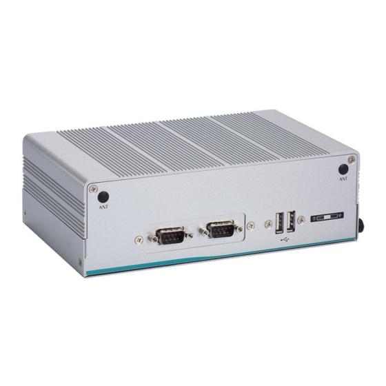
Page 16: I/O Outlets
User’s Manual I/O Outlets The following figures show you I/O outlets on front view of the eBOX627-312-FL. Front View Front View drawing Introduction... - Page 17 User’s Manual Rear View Rear View drawing Introduction...
-
Page 18: Packing List
mSATA Storage Device (optional) DDR3L SODIMM (optional) WIFI / 3G / LTE Modules (optional) If you cannot find this package or any items are missing, please contact Axiomtek distributors immediately. Model List ® ® Fanless Embedded... -
Page 19: Chapter 2 Hardware Installation
CHAPTER 2 HARDWARE INSTALLATION The eBOX627-312-FL is convenient for your various hardware configurations, such as Memory Module, HDD (Hard Disk Drive), SSD (Solid State Drive), Flexible I/O and mSATA. The chapter 2 will show you how to install the hardware. - Page 20 User’s Manual Step 5 Holding the DDR3L SO-DIMM at a 30 degree angle up from horizontal, slowly insert the golden fingers into the DDR3L SO -DIMM slot until it is fully inserted in. Step 6 Press it down gently, until it is firmly seated by locking two latches on the sides.
-
Page 21: Installing The Pci Express Mini Card
User’s Manual Installing the PCI Express Mini Card Step 1 Turn off the system, and unplug the power cord. Step 2 Turn the system upside down to locate screws at the side of the system, and then loosen four screws. - Page 22 User’s Manual Step 5 Holding the PCI Express mini card at a 45 degree angle up from horizontal, slowly insert the golden fingers into the PCI Express slot until it is fully inserted in. Step 6 Press it down gently, but firmly, and then secure the PCI Express mini card to the carrier by tightening up the one M2*5L Phillips pan head screw to the marked position.
-
Page 23: Installing The Flexible I/O Window Kit
User’s Manual Installing the Flexible I/O Window Kit The eBOX627-312-FL provides an optional window for customer add flexible I/O modules, as following list: AX92902 LAN Module AX92903 CAN Bus Module AX92903 CAN Bus w/ CAN Open Module AX92904 DIO Module... - Page 24 User’s Manual Step 4 Prepare the CAN Bus module kit. Step 5 Assemble CAN Bus connector with bracket. Step 6 Loosen two screws to remove the bracket from the panel. Hardware Installation...
- Page 25 User’s Manual Step 7 Fasten the CAN Bus bracket into the chassis. Step 8 install the mini PCIe card on the board. Step 9 Connect the CAN Bus cable to the mini PCIe module. Hardware Installation...
-
Page 26: Installing The 2.5" Sata Device
User’s Manual Installing the 2.5” SATA Device Step 1 Turn off the system, and unplug the power cord. Step 2 Locate screws at the right side, loosen two screws. Step 3 Pull out the HDD/SSD drive bay bracket. Step 4 Please prepare HDD/SSD and four M3*4L Phillips flat head screws. - Page 27 User’s Manual Step 5 Fasten four screws to fix HDD/SSD. Step 6 Connect the SSD directly and make sure the insertion is complet e and fasten two screws. Note: Please notice the direction of connector for HDD/SSD. Hardware Installation...
- Page 28 User’s Manual This page is intentionally left blank. Hardware Installation...
-
Page 29: Chapter 3 Jumper Setting & Connector
User’s Manual CHAPTER 3 JUMPER SETTING & CONNECTOR Proper jumper settings configure the eBOX627-312-FL to meet your application purpose. We are herewith listing a summary table of all jumpers and default settings for onboard devices, respectively. CAPA312 layout Top View... - Page 30 User’s Manual Bottom View NOTE: We strongly recommended that you should not modify any unmentioned jumper setting without Axiomtek FAE’s instruction. Any modification without instruction might cause system to become damage. Jumper Setting & Connector...
-
Page 31: Jumper Setting Summary
User’s Manual Jumper Setting Summary Proper jumper settings configure the eBOX627-312-FL to meet your application purpose. We are herewith listing a summary table of all jumpers and default settings for onboard devices, respectively. Jumper and Description Setting Switch Restore BIOS Optimal Defaults... -
Page 32: Com3 Data/Power Selection (Jp4)
User’s Manual 3.2.2 COM3 Data/Power Selection (JP4) This is a 2x3-pin (pitch=2.0mm) jumper. The COM3 port has +5V level power capability on DCD and +12V level on RI by setting jumper JP4. Function Setting Power: Set CN4 pin 1 to +5V level... -
Page 33: Connectors
Connectors connect the board with other parts of the system. Loose or improper connection might cause problems. Make sure all connectors are properly and firmly connected. Here is a summary table shows you all connectors and button on the eBOX627-312-FL Series. Location... -
Page 34: Com Serial Port Connector (Cn22, Cn18, Cn4 And Cn3 )
User’s Manual 3.3.1 COM Serial Port Connector (CN22, CN18, CN4 and CN3 ) The system has four serial ports. COM1 and COM2 are RS-232/422/485 ports; COM3 and COM4 are RS-232 ports. Please refer to Chapter 4 for the detail of BIOS setting. -
Page 35: Sata Connector (Cn15)
User’s Manual 3.3.3 SATA Connector (CN15) This Serial Advanced Technology Attachment (Serial ATA or SATA) connector is for high-speed SATA interface. It is a computer bus interface for connecting to devices such as hard disk drive. Signal SATA_TXP0 SATA_TXN0... -
Page 36: Usb 3.0 Ports (Cn20 And Cn21)
User’s Manual 3.3.5 USB 3.0 Ports (CN20 and CN21) The Universal Serial Bus (compliant with USB 3.0 (5Gb/s) connector on the rear I/O is for installing USB peripherals such as keyboard, mouse, scanner, etc. USB 3.0 port 0 and 1 (CN20):... -
Page 37: Ethernet Ports (Lan1 And Lan2)
User’s Manual 3.3.6 Ethernet Ports (LAN1 and LAN2) The system supports two RJ-45 connectors: LAN1 and LAN2. Ethernet connection can be established by plugging one end of the Ethernet cable into this RJ-45 connector and the other end (phone jack) to a 1000/100/10-Base-T hub. -
Page 38: Full-Size Pci-Express Mini Card Connector (Scn1)
User’s Manual 3.3.7 Full-size PCI-Express Mini Card Connector (SCN1) This is a full-size PCI-Express Mini Card connector on the bottom side supporting PCI- Express x1 or USB 2.0. It also complies with PCI-Express Mini Card Spec. V1.2. Signal Signal WAKE# +3.3VSB... -
Page 39: Sim Card Socket (Scn2)
User’s Manual 3.3.8 SIM Card Socket (SCN2) The system has SCN2 socket on the bottom side for inserting SIM Card. In order to work properly, the SIM Card must be used together with 3G/LTE module which is inserted to SCN1 or SCN3. -
Page 40: Full-Size Pci-Express Mini Card Or Msata Connector (Scn3)
User’s Manual 3.3.9 Full-size PCI-Express Mini Card or mSATA Connector (SCN3) This is a full-size PCI-Express Mini Card connector on the bottom side complying with PCI- Express Mini Card Spec. V1.2. It supports either PCI-Express, USB 2.0 or SATA (mSATA). -
Page 41: Power And Hdd Led Indicator
User’s Manual 3.3.10 Power and HDD LED Indicator The Yellow LED is linked to Hard Disk Drive (HDD) activity signal. LED flashes every time HDD is accessed. The power LED (Green) lights up and will remain steady while the system is powered on. - Page 42 User’s Manual This page is intentionally left blank. Jumper Setting & Connector...
-
Page 43: Chapter 4 Bios Setup Utility
User’s Manual CHAPTER 4 BIOS SETUP UTILITY This chapter provides users with detailed description how to set up basic system configuration through the BIOS setup utility. Starting To enter the setup screens, follow the steps below: Turn on the computer and press the <Del> key immediately. -
Page 44: Main Menu
User’s Manual Main Menu When you first enter the setup utility, you will enter the Main setup screen. You can always return to the Main setup screen by selecting the Main tab. System Time/Date can be set up as described below. -
Page 45: Advanced Menu
User’s Manual Advanced Menu The Advanced menu also allows users to set configuration of the CPU and other system devices. You can select any of the items in the left frame of the screen to go to the sub menus: ►... - Page 46 User’s Manual Hardware Monitor This screen monitors hardware health status. This screen displays the temperature of system and CPU, fan speed in RPM and system voltages (VBAT, +3.3V, +3.3VSB and +5VSB). BIOS Setup Utility...
- Page 47 User’s Manual ACPI Settings ACPI Sleep State Select the ACPI (Advanced Configuration and Power Interface) sleep state. Configuration options are Suspend Disabled and S3 (Suspend to RAM). The S3 (Suspend to RAM) option selects ACPI sleep state the system will enter when suspend button is pressed.
- Page 48 User’s Manual Trusted Computing This screen provides function for specifying the TPM settings. Security Device Support Enable or disable BIOS support for security device. The default setting is Enable. TPM Device Enable or disable TPM device. Current Status Information Display current TPM status information.
- Page 49 User’s Manual Pending operation Schedule a TPM operation which will take effect at the next bootup process. BIOS Setup Utility...
- Page 50 User’s Manual Super IO Configuration You can use this screen to select options for the Super IO Configuration, and change the value of the selected option. A description of the selected item appears on the right side of the screen.
- Page 51 User’s Manual Serial Port 1 (COM1) Configuration Serial Port Enable or disable serial port 1. The optimal setting for base I/O address is 3F8h and for interrupt request address is IRQ4. COM Port Type Use this option to set RS-232/RS-422/RS-485 mode.
- Page 52 User’s Manual Serial Port 2 (COM2) Configuration Serial Port Enable or disable serial port 2. The optimal setting for base I/O address is 2F8h and for interrupt request address is IRQ3. COM Port Type Use this option to set RS-232/RS-422/RS-485 mode.
- Page 53 User’s Manual Serial Port 3 (COM3) Configuration Serial Port Enable or disable serial port 3. The optimal setting for base I/O address is 3E8h and for interrupt request address is IRQ11. COM Port Type RS-232 mode. BIOS Setup Utility...
- Page 54 User’s Manual Serial Port 4 (COM4) Configuration Serial Port Enable or disable serial port 4. The optimal setting for base I/O address is 2E8h and for interrupt request address is IRQ10. COM Port Type RS-232 mode. BIOS Setup Utility...
- Page 55 User’s Manual CPU Configuration This screen shows the CPU Configuration. Intel Virtualization Technology Allow a hardware platform to run multiple operating systems separately and simultaneously, enabling one system to virtually function as several systems. BIOS Setup Utility...
- Page 56 User’s Manual Turbo Mode This item is for enabling or disabling turbo mode. When enabled, it allows processor cores to run faster than marked frequency under certain conditions. The default is Turbo Mode. BIOS Setup Utility...
- Page 57 User’s Manual SATA Configuration In the SATA Configuration menu, you can see the currently installed hardware in the SATA ports. During system boot up, the BIOS automatically detects the presence of SATA devices. Chipset SATA Enable or disable Chipset Controller feature. The default is Enabled.
- Page 58 User’s Manual USB Configuration USB Devices Display all detected USB devices. BIOS Setup Utility...
- Page 59 User’s Manual Utility Configuration BIOS Flash Utility You can execute the BIOS flasher. BIOS Setup Utility...
-
Page 60: Chipset Menu
User’s Manual Chipset Menu The Chipset menu allows users to change the advanced chipset settings. You can select any of the items in the left frame of the screen to go to the sub menus: ► North Bridge ►... - Page 61 User’s Manual North Bridge Memory Information Display system memory information. BIOS Setup Utility...
- Page 62 User’s Manual South Bridge This screen allows users to configure parameters of South Bridge chipset. BIOS Setup Utility...
-
Page 63: Security Menu
User’s Manual Security Menu The Security menu allows users to change the security settings for the system. Setup Administrator Password This item indicates whether an administrator password has been set (installed or uninstalled). User Password This item indicates whether an user password has been set (installed or uninstalled). -
Page 64: Boot Menu
User’s Manual Boot Menu The Boot menu allows users to change boot options of the system. Setup Prompt Timeout Number of seconds to wait for setup activation key. 65535 (0xFFFF) means indefinite waiting. Bootup NumLock State Use this item to select the power-on state for the keyboard NumLock. -
Page 65: Save & Exit Menu
User’s Manual Save & Exit Menu The Save & Exit menu allows users to load your system configuration with optimal or fail-safe default values. Save Changes and Exit When you have completed the system configuration changes, select this option to leave Setup and return to Main Menu. - Page 66 User’s Manual Discard Changes and Reset Select this option to quit Setup without making any permanent changes to the system configuration and reboot the computer. Select Discard Changes and Reset from the Save & Exit menu and press <Enter>. Select Yes to discard changes and reset.
-
Page 67: Appendix Awatchdog Timer
User’s Manual APPENDIX A WATCHDOG TIMER About Watchdog Timer After the system stops working for a while, it can be auto-reset by the watchdog timer. The integrated watchdog timer can be set up in the system reset mode by program. - Page 68 User’s Manual This page is intentionally left blank. Watchdog Timer...
-
Page 69: Appendix Bbios Flash Utility
Please read and follow the instructions below carefully. In your USB flash drive, create a new folder and name it “Axiomtek”, see figure below. Copy BIOS ROM file (e.g. CAPA312.005) to “Axiomtek” folder. - Page 70 Select the USB drive containing BIOS ROM file you want to update using the <> or <> key. Then press <Enter> to get into “Axiomtek” folder. Now you can see the BIOS ROM file on the screen, press <Enter> to select.
- Page 71 User’s Manual Please wait while BIOS completes the entire flash update process: erase data, write new data and verify data. 10. When you see the following figure, press <Enter> to finish the update process. After that the system will shut down and restart immediately.
- Page 72 User’s Manual This page is intentionally left blank. BIOS Flash Utility...
Need help?
Do you have a question about the eBOX627-312-FL and is the answer not in the manual?
Questions and answers