Table of Contents
Advertisement
Quick Links
Advertisement
Chapters
Table of Contents

Related Manuals for AXIOMTEK eBOX630-100-FL Series


Summary of Contents for AXIOMTEK eBOX630-100-FL Series
- Page 1 Series Embedded System User’s Manual...
- Page 2 Disclaimers This manual has been carefully checked and believed to contain accurate information. A Co., Ltd. assumes no responsibility for xiomtek any infringements of patents or any third party’s rights, and any liability arising from such use. does not warrant or assume any legal liability or responsibility xiomtek for the accuracy, completeness or usefulness of any information in this document.
-
Page 3: Safety Precautions
Before getting started, please read the following important safety precautions. User should not modify any unmentioned jumper setting without Axiomtek FAE’s instruction. Any modification without instruction might cause system to become damage The eBOX620-110-FL does not come equipped with an operating system. -
Page 4: Classification
Classification Degree of production against electric shock : not classified Degree of protection against the ingress of water : IP40 Equipment not suitable for use in the presence of a flammable anesthetic mixture with air or with oxygen or nitrous oxide. Mode of operation : Continuous... -
Page 5: General Cleaning Tips
General Cleaning Tips You may need the following precautions before you begin to clean the computer. When you clean any single part or component for the computer, please read and understand the details below fully. When you need to clean the device, please rub it with a piece of dry cloth. - Page 6 Vacuum cleaner: Absorb the dust, dirt, hair, cigarette particles, and other particles out of a computer can be one of the best methods of cleaning a computer. Over time these items can restrict the airflow in a computer and cause circuitry to corrode.
-
Page 7: Scrap Computer Recycling
If the computer equipments need the maintenance or are beyond repair, we strongly recommended that you should inform your Axiomtek distributor as soon as possible for the suitable solution. For the computers that are no longer useful or no longer working well, please contact your Axiomtek distributor for recycling and we will make the proper arrangement. -
Page 8: Table Of Contents
Table of Contents Disclaimers ..................ii Safety Precautions ................ iii Classification ................. iv General Cleaning Tips ..............v Scrap Computer Recycling ............vii CHAPTER 1 INTRODUCTION ............1 General Description ............ 2 System Specifications ..........3 1.2.1 CPU ................3 1.2.2 System I/O .............. - Page 9 3.3.7 ATX Power On/OFF Button ........44 3.3.8 Audio Connector ............44 3.3.9 SATA Connector ............44 3.3.10 CFast™ Socket............45 3.3.11 DDR3 SODIMM Socket ..........46 3.3.12 PCI-Express MiniCard ..........46 3.3.13 PCI-Express MiniCard ..........47 CHAPTER 4 AMI BIOS SETUP UTILITY ........49 Starting ..............
- Page 10 MEMO...
-
Page 11: Chapter 1 Introduction
Series User’s Manual CHAPTER 1 INTRODUCTION This chapter contains general information and detailed specifications of the eBOX630-100-FL. The Chapter 1 includes the following sections: General Description System Specification Dimensions I/O Outlets Package List Introduction... -
Page 12: General Description
Series User’s Manual General Description The eBOX630-100-FL is an embedded system that supports AMD G- series APU T56N 1.65GHz dual core onboard processor with AMD ® ® FCH A50M chipset. It can provide Windows XPE, Windows ® Windows WinCE embedded and Linux, suitable for the most endurable operation.It features fanless design with full feature I/O, one... -
Page 13: System Specifications
Series User’s Manual System Specifications 1.2.1 AMD G-Series APU dual core T56N 1.65GHz Chipset AMD FCH A50M BIOS American Megatrends Inc. UEFI (Unified Extensible Firmware Interface) BIOS. 16Mbit SPI Flash, DMI, Plug and Play. - Page 14 Series User’s Manual Storage Temperature -20℃ ~ 80℃ (-4 ºF ~ 176ºF) Humidity 10% ~ 90% (non-condensation) Vibration Endurance 2Grms w/ CF (5 ~ 500Hz, X, Y, Z directions) Weight 2.5 kg (5.51 lb) without package ...
-
Page 15: I/O Port Address Map
Series User’s Manual 1.2.4 I/O Port Address Map The AMD G-Series APU communicates via I/O ports. Total 1KB port addresses are available for assigning to other devices via I/O expansion cards. Introduction... - Page 16 Series User’s Manual Introduction...
-
Page 17: Interrupt Controller
Series User’s Manual 1.2.5 Interrupt Controller The eBOX630-100-FL is 100% PC compatible control board which consists of 20 interrupt request lines. Four out of 20 can be programmable. The mapping list of the 20 interrupt request lines is shown as the following table. -
Page 18: Driver Cd Content
Series User’s Manual 1.2.6 Driver CD Content Win7 AHCI Audio Chip WinXP AHCI Audio Chip Linux Chipset Audio Manual Quick Manual User Manual... -
Page 19: Dimensions
Series User’s Manual Dimensions The following diagrams show you dimensions and outlines of the eBOX630-100-FL. Introduction... -
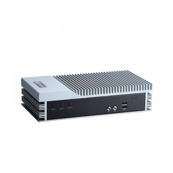
Page 20: I/O Outlets
Series User’s Manual I/O Outlets The following figures show you I/O outlets on front view of the eBOX630-100-FL. Front View of eBOX630-100-FL Front View drawing Power & HDD Indicators Audeio 2 x USB 2.0 SMA Antenna connectors... - Page 21 Series User’s Manual Rear View Rear View drawing 4 x USB 2.0 connectors 12V DC-IN power DisplayPorts input connector 2 x RJ45 connector Gbe LANs Power COM1/2 Front Access COM3/4 switch connectors CF slot cover connectors Introduction...
-
Page 22: Packing List
Series User’s Manual Packing List The package bundled with your eBOX630-100-FL should contain the following items: eBOX630-100-FL System Unit x 1 eBOX630-100-FL Quick Manual x 1 CD x 1 (For Driver and User’s Manual) Screws pack x1 ... -
Page 23: Chapter 2 Hardware Installation
Series User’s Manual CHAPTER 2 HARDWARE INSTALLATION The eBOX630-100-FL is convenient for your various hardware configurations, such as Memory Module, HDD (Hard Disk Drive), and CFast card. The chapter 2 will show you how to install the hardware. Hardware Installation... -
Page 24: Installing The Memory Module
Series User’s Manual Installing the Memory Module Step 1) Turn off the system, and unplug the power cord. Step 2) Turn the system upside down to locate screws at the bottom, loosen screws. Hardware Installation... - Page 25 Series User’s Manual Step 3) Remove the bottom cover. Step 4) Locate the memory socket, insert the gold colored contact into the socket. Hardware Installation...
- Page 26 Series User’s Manual Step 5) Push the module down, until it is firmly seated by locking two latches on the sides. Step 6) Close the cover to the chassis, and fasten all screws. Hardware Installation...
-
Page 27: Installing The Sata Hdd
Series User’s Manual Installing the SATA HDD Step 1) Turn off the system, and unplug the power cord. Step 2) Turn the system upside down to locate screws at the bottom, loosen screws. Hardware Installation... - Page 28 Series User’s Manual Step 3) Remove the bottom cover. Step 4) Loosen screws of HDD bracket Hardware Installation...
- Page 29 Series User’s Manual Step 5) Pick up the HDD bracket, place it with HDD and make sure if the direction is correct Step 6) Put the bracket upon the HDD, assembly the HDD bracket together with the SATA HDD...
- Page 30 Series User’s Manual Step 7) Connect SATA cable and power cable to SATA HDD. Step 8) Install the HDD bracket backto the chassis, and fasten all screws. Hardware Installation...
- Page 31 Series User’s Manual Step 9) Close the cover to the chassis, and fasten all screws. Hardware Installation...
-
Page 32: Installing The Cfast Card
Series User’s Manual Installing the CFast Card Step 1) Turn off the system, and unplug the AC/DC power cord. Step 2) Turn the system rotate to CF cover side and locate screws at the front side. Step 3) Loosen screws to remove the CFast slot cover. - Page 33 Series User’s Manual Step 4) Stick the Mylar onto the CFast card Mylar fin for hand hold CFast card connector Step 5) Slide CFast card into CFast slot cautionly Hardware Installation...
- Page 34 Series User’s Manual Step 6) Close the cover to the chassis, and fasten all screws. Hardware Installation...
-
Page 35: Installing The Sim Card
Series User’s Manual Installing the SIM Card Step 1) Turn the system upside down to locate screws at the bottom, loosen screws. Hardware Installation... - Page 36 Series User’s Manual Step 2) Remove the bottom cover. Step 3) Locate the SIM socket, push the SIM socket cover and then open it. Hardware Installation...
- Page 37 Series User’s Manual Step 4) Insert SIM card. Step 5) Close the socket and then push the SIM socket back to lock the socket Hardware Installation...
- Page 38 Series User’s Manual Step 6) Close the cover to the chassis, and fasten all screws. Hardware Installation...
-
Page 39: Installing The Express Mini Card
Series User’s Manual Installing the Express Mini Card Step 2) Turn the system upside down to locate screws at the bottom, loosen screws. Hardware Installation... - Page 40 Series User’s Manual Step 3) Remove the bottom cover. Step 4) Locate the MiniCard socket, push the SIM socket cover and then open it. Hardware Installation...
- Page 41 Series User’s Manual Step 5) Slide Mini card into MiniCard slot cautionly Step 6) Fasten screw of Express Mini Card. Hardware Installation...
- Page 42 Series User’s Manual Step 7) Close the cover to the chassis, and fasten all screws. Hardware Installation...
-
Page 43: Chapter 3 Jumper Setting & Connector
Series User’s Manual CHAPTER 3 Jumper Setting & Connector Proper jumper settings configure the eBOX630-100-FL to meet your application purpose. We are herewith listing a summary table of all jumpers and default settings for onboard devices, respectively. Jumper Setting & Connector... -
Page 44: Sbc Layout
Series User’s Manual SBC layout Component Side Jumper Setting & Connector... - Page 45 Series User’s Manual Solder Side Jumper Setting & Connector...
-
Page 46: Jumper Setting Summary
Series User’s Manual Jumper Setting Summary Jumper is a small component consisting of jumper clip and jumper pins. Install jumper clip on 2 jumper pins to close. And remove jumper clip from 2 jumper pins to open. Below illustration shows how to set up jumper. -
Page 47: Audio Output Selection Jumper (Jp1)
Series User’s Manual 3.2.1 Audio Output Selection Jumper (JP1) JP1 is to select line out or speaker out as source of audio output on audio connector CN2. W hen speaker out is used, it delivers 1W /channel continuous at 8 Ohm loads. -
Page 48: Cmos Clear Jumper (Jp11)
Series User’s Manual 3.2.3 CMOS Clear Jumper (JP11) Put jumper clip to pin 2-3 for a few seconds then move it back to pin 1-2. Doing this procedure can restore BIOS optimal defaults. Function Setting Normal (Default) 1-2 close... -
Page 49: Connectors
Connectors connect the board with other parts of the system. Loose or improper connection might cause problems. Make sure all connectors are properly and firmly connected. Here is a summary table shows you all connectors on the eBOX630-100-FL Series. External Connectors Section DC-in Jack Power Connector 3.3.1... -
Page 50: Serial Port Connector
Series User’s Manual 3.3.2 Serial Port Connector The system has three serial ports. COM1 ~COM4 are RS-232 ports. Description DCD, Data Carrier Detect COM1~4 RXD, Receive Data TXD, Transmit Data DTR, Data Terminal Ready GND, Ground DSR, Data Set Ready... -
Page 51: Displayport Connector
Series User’s Manual 3.3.3 DisplayPort Connector Two DisplayPort interfaces are available through connectors DisplayPort 0 and DisplayPort 1. Signal DPB_LANE0 DPB_LANE0# DPB_LANE1 DPB_LANE1# DPB_LANE2 DPB_LANE2# DPB_LANE3 DPB_LANE3# Detect Pin DPB_AUX DPB_AUX# DPB_HPDE +3.3V Jumper Setting & Connector... -
Page 52: Vga Connector
Series User’s Manual 3.3.4 VGA Connector The VGA connector is a slim type 15-pin D-Sub connector which is common for the CRT VGA display. The VGA interface configuration can be configured via the software utility. Signal Signal Signal Green Blue N.C. -
Page 53: Lan Connector (Lan1, Lan2)
Series User’s Manual 3.3.5 LAN Connector (LAN1, LAN2) The RJ-45 connector is for Ethernet. To connect the board to a 1000/100/10 Base-T hub, just plug one end of the cable into connector and connect the other end (phone jack) to a... -
Page 54: Atx Power On/Off Button
Series User’s Manual 3.3.7 ATX Power On/OFF Button The ATX power button is on the I/O side. It can allow users to control eBOX630-100-FL power on/off. Signal PSIN 3.3.8 Audio Connector These two audio jacks ideal are for Audio Mic -In and Audio Line-out. -
Page 55: 3.3.10 Cfast™ Socket
Series User’s Manual 3.3.10 CFast™ Socket The System is equipped with a CFast™ socket on the bottom side to support a CFast™ card which is based on the Serial ATA bus. The socket is specially designed to avoid incorrect installation of the CFast™... -
Page 56: 3.3.11 Ddr3 Sodimm Socket
Series User’s Manual 3.3.11 DDR3 SODIMM Socket eBOX630-100-FL supports standard DDR3 204-pin 800/1066 MHz SO-DIMM pin define. 3.3.12 PCI-Express MiniCard eBOX630-100-FL includes one SIM slot on the bottom side of the system for Inserting SIM Card. In order to work properly, the SIM Card must be used together with Mini Card which is inserted to socket SCN1. -
Page 57: Pci-Express Minicard
Series User’s Manual 3.3.13 PCI-Express MiniCard eBOX630-100-FL includes PCI-Express Mini Card sockets which support PCI-Express x1 link and USB 2.0 link. A PCI-Express Mini Card can be applied to either PCI-Express or USB 2.0. It complies with PCI-Express Mini Card Spec. V1.2. - Page 58 Series User’s Manual SCN1 Jumper Setting & Connector...
-
Page 59: Chapter 4 Ami Bios Setup Utility
Series User’s Manual CHAPTER 4 AMI BIOS SETUP UTILITY The AMI UEFI BIOS provides users with a built-in setup program to modify basic system configuration. All configured parameters are stored in a 16MB flash chip to save the setup information whenever the power is turned off. -
Page 60: Starting
Series User’s Manual Starting To enter the setup screens, follow the steps below: Turn on the computer and press the <Del> key immediately. After you press the <Del> key, the main BIOS setup menu displays. You can access the other setup screens from the main BIOS setup menu, such as the Advanced and Chipset menus. -
Page 61: Navigation Keys
Series User’s Manual Navigation Keys The BIOS setup/utility uses a key-based navigation system called hot keys. Most of the BIOS setup utility hot keys can be used at any time during the setup navigation process. These keys include <F1>, <F2>, <Enter>, <ESC>, <Arrow>... -
Page 62: Main Menu
Series User’s Manual Main Menu When you first enter the setup utility, you will enter the Main setup screen. You can always return to the Main setup screen by selecting the Main tab. System Time/Date can be set up as described below. The Main BIOS setup screen is shown below. -
Page 63: Advanced Menu
Series User’s Manual Advanced Menu Launch PXE OpROM Use this item to enable or disable the boot ROM function of the onboard LAN chip when the system boots up. The Advanced menu also allows users to set configuration of the CPU and other system devices. - Page 64 Series User’s Manual ACPI Settings You can use this screen to select options for the ACPI configuration, and change the value of the selected option. A description of the selected item appears on the right side of the screen.
- Page 65 Series User’s Manual CPU Configuration This screen shows the CPU Configuration. Node 0 Information View memory information related to Node AMI BIOS Setup Utility...
- Page 66 Series User’s Manual IDE Configuration In the IDE Configuration menu, you can see the currently installed hardware in the SATA ports. During system boot up, the BIOS automatically detects the presence of SATA devices. AMI BIOS Setup Utility...
- Page 67 Series User’s Manual USB Configuration You can use this screen to select options for the USB Configuration, and change the value of the selected option. A description of the selected item appears on the right side of the screen.
- Page 68 Series User’s Manual W83627UHG Super IO Configuration You can use this screen to select options for the Super IO Configuration, and change the value of the selected option. A description of the selected item appears on the right side of the screen. For items marked with “”, please press <Enter>...
- Page 69 Series User’s Manual H/W Monitor This screen monitors hardware health status. This screen displays the temperature of system and CPU, cooling fan speed in RPM and system voltages (VCORE, +12V, +5V and +3.3V). AMI BIOS Setup Utility...
-
Page 70: Chipset Menu
Series User’s Manual Chipset Menu The Chipset menu allows users to change the advanced chipset settings. You can select any of the items in the left frame of the screen to go to the sub menus: ► North Bridge ►... - Page 71 Series User’s Manual North Bridge Configuration This screen allows users to configure parameters of North Bridge chipset. AMI BIOS Setup Utility...
- Page 72 Series User’s Manual Memory Configuration All of options are set Auto as default. AMI BIOS Setup Utility...
- Page 73 Series User’s Manual Node 0 Information This item is to provide user with the information of current using DDR3 SDRAMs. AMI BIOS Setup Utility...
- Page 74 Series User’s Manual North Bridge LVDS Config Select DP0 Output Mode Use this item to choose Display Port0 output or disable mode. DP1 Output Mode Use this item to choose Display Port1 output or disable mode.
- Page 75 Series User’s Manual South Bridge This screen allows users to configure South Bridge chipset. For items marked with “”, please press <Enter> for more options. ► SB SATA Configuration ► SB USB Configuration ► SB HD Azalia Configuration...
- Page 76 Series User’s Manual SB SATA Configuration Use this item to select options for SATA configuration. OnChip SATA Channel Use this item to enable or disable SATA channel. OnChip SATA Type Here are the options: Native IDE and AHCI.
- Page 77 Series User’s Manual SB USB Configuration Use this item to enable or disable all of USB devices. AMI BIOS Setup Utility...
- Page 78 Series User’s Manual SB HD Azalia Configuration This item allows you to enable or disable HD audio Azalia device. AMI BIOS Setup Utility...
-
Page 79: Boot Menu
Series User’s Manual Boot Menu The Boot menu allows users to change boot options of the system. Setup Prompt Timeout Number of seconds to wait for setup activation key. 65535(0xFFFF) means indefinite waiting. Bootup NumLock State Use this item to select the power-on state for the NumLock. -
Page 80: Security Menu
Series User’s Manual Security Menu The Security menu allows users to change the security settings for the system. Administrator Password This item indicates whether an administrator password has been set (installed or uninstalled). User Password This item indicates whether an user password has been set (installed or uninstalled). -
Page 81: Save & Exit Menu
Series User’s Manual Save & Exit Menu The Save & Exit menu allows users to load your system configuration with optimal or fail-safe default values. Save Changes and Exit When you have completed the system configuration changes, select this option to leave Setup and return to Main Menu. - Page 82 Series User’s Manual Discard Changes and Reset Select this option to quit Setup without making any permanent changes to the system configuration and reboot the computer. Select Discard Changes and Reset from the Save & Exit menu and press <Enter>. Select Yes to discard changes and reset.
-
Page 83: Appendix Awatchdog Timer
Series User’s Manual APPENDIX A WATCHDOG TIMER About Watchdog Timer Software stability is major issue in most application. Some embedded systems are not watched by human for 24 hours. It is usually too slow to wait for someone to reboot when computer hangs. The systems need to be able to reset automatically when things go wrong. - Page 84 Series User’s Manual Begin Begin Next Next Enable and Initialize Enable and Initialize Watchdog Timer Watchdog Timer Next Next Program “A” Program “A” Next Next Disable Watchdog Reset Watchdog Timer Timer Next Next Watchdog Timer...
- Page 85 Series User’s Manual Sample Program Assembly sample code : ;Enable WDT: dx,2Eh al,87 ;Un-lock super I/O dx,al dx,al ;Select Logic device: dx,2Eh al,07h dx,al dx,2Fh al,08h dx,al ;Activate WDT: dx,2Eh al,30h dx,al dx,2Fh al,01h dx,al Watchdog Timer...
- Page 86 Series User’s Manual ;Set Second or Minute : dx,2Eh al,0F5h dx,al dx,2Fh al,Nh ;N=00h or 08h(see below Note dx,al ;Set base timer : dx,2Eh al,0F6h dx,al dx,2Fh al,Mh ;M=00h,01h,...FFh (hex),Value=0 to 255 Note dx,al ;(see below ;Disable WDT: dx,2Eh...
- Page 87 Series User’s Manual Note: If N=00h, the time base is set to second. M = time value 00: Time-out Disable 01: Time-out occurs after 1 second 02: Time-out occurs after 2 seconds 03: Time-out occurs after 3 seconds FFh: Time-out occurs after 255 seconds If N=08h, the time base is set to minute.
- Page 88 Series User’s Manual MEMO: Watchdog Timer...
Need help?
Do you have a question about the eBOX630-100-FL Series and is the answer not in the manual?
Questions and answers