Table of Contents
Advertisement
Advertisement
Table of Contents

Related Manuals for Eaton IQ 100 series


Summary of Contents for Eaton IQ 100 series
- Page 1 IQ 100 Series (130/140/150) Meter User & Installation Manual IM02601003E Rev D...
- Page 2 THEREON, IS CONFIDENTIAL AND IS THE EXCLUSIVE PROPERTY OF EATON CORPO- RATION, AND IS MERELY ON LOAN AND SUBJECT TO RECALL BY EATON AT ANY TIME. BY TAKING POSSESSION OF THIS DOCUMENT, THE RECIPIENT ACKNOWL- EDGES AND AGREES THAT THIS DOCU-...
-
Page 3: Table Of Contents
2. Service: 2.5 Element WYE, 4-Wire with No PTs, 3 CTs 3. Service: WYE, 4-Wire with 3 PTs, 3 CTs 4. Service: 2.5 Element WYE, 4-Wire with 2 PTs, 3 CTs 29 User and Installation Manual IM02601003E - July 2010 www.eaton.com... - Page 4 RS485 / KYZ Output (Communication Option) For All RS485 Connections: IQ 100 Series Transducer Communication Information 40 Meter Connection Programming the IQ 100 Series Meter Using the Front Panel Introduction Understanding Meter Face Elements Understanding Meter Face Buttons Using the Front Panel 42...
- Page 5 App.B Modbus Mapping for IQ 100 Series 73 Introduction Modbus Register Map Sections 73 Floating Point Values 74 Important Note Concerning the IQ 100 Series Modbus Map Modbus Register Map (MM-1 to MM-16) 75 User and Installation Manual IM02601003E - July 2010 www.eaton.com...
- Page 6 IQ 100 Series (130/140/150) Meter Table of Contents User and Installation Manual IM02601003E-July 2010 www.eaton.com...
-
Page 7: Disclaimer Of Warranties And Limitation Of Liability
TION OF EATON. THE CONTENTS OF THIS DOCUMENT SHALL NOT BECOME PART OF OR MODIFY ANY CONTRACT BETWEEN THE PARTIES. In no event will Eaton be responsible to the purchaser or user in contract, in tort (including negligence), strict liability or otherwise for any special, indirect, incidental or consequential damage or loss... - Page 8 IQ 100 Series (130/140/150) Meter Disclaimer of Warranties and Limitation of Liability User and Installation Manual IM02601003E-July 2010 www.eaton.com...
-
Page 9: Support Services
Support Services Support Services Support Services The goal of Eaton is to ensure your greatest possible satisfaction with the operation of our products. We are dedicated to providing fast, friendly and accurate assistance. That is why we offer you so many ways to get the support you need. Whether it’s by phone, fax or e-mail, you can access Eaton’s support... -
Page 10: Technical Resource Center
OI product, contact your local distributor. Repair and Upgrade Service (support for OI) Voice: 877-ETN-CARE (877-386-2273) (8:00 am – 5:00 pm EST) 414-449-7100 (8:00 am – 5:00 pm EST) FAX: 614-882-3414 e-mail: TRC@eaton.com User and Installation Manual IM02601003E-July 2010 www.eaton.com... -
Page 11: Iq 100 Series Meter Overview And Specifications
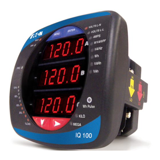
• Easy to Use Faceplate Programming The IQ 100 Series meter is available in two configurations: meter/transducer and transducer only. IQ 100 Series Meter / Digital Transducer Meter and transducer in one compact unit. Features an optional RS485 and KYZ Pulse Output, and can be programmed using the faceplate of the meter. -
Page 12: Current Inputs
IQ 100 Series (130/140/150) Meter Overview &Specifications Current Inputs The IQ 100 Series meter’s Current Inputs use a unique dual input method: • Method 1: CT Pass Through The CT passes directly through the meter without any physical termination on the meter. This insures that the meter cannot be a point of failure on the CT circuit. -
Page 13: Measured Values
IQ 100 Series ((130/140/150) Meter Overview & Specifications Measured Values The following table lists the measured values available for the different IQ 100 Series models. IQ 100 Series Feature Comparison Readings/Features IQ 130 IQ 140 IQ150 Volts L-N Volts L-N Max/Min... -
Page 14: Utility Peak Demand (Iq140/150)
Overview &Specifications Utility Peak Demand (IQ140/150) The IQ 100 Series meter provides user-configured Fixed Window or Sliding Window Demand. This feature allows you to set up a Customized Demand Profile. Fixed Window Demand is demand used over a user-configured demand period (usually 5, 15 or 30 minutes). Sliding Window Demand is a fixed window demand that moves for a user-specified subinterval period. - Page 15 (H4.85 x W4.82 x L4.25) inches, (H123.2 x W123.2 x L105.4) mm Mounts in 92mm square DIN or ANSI C39.1, 4” Round Cut-out · Weight: 2 pounds, 0.907kg (ships in a 6”/152.4mm cube container) User and Installation Manual IM02601003E - July 2010 www.eaton.com...
-
Page 16: Compliance
% of Load Bar 1-120% 10 Segment Resolution Scalable *Accuracy stated for 5Amp secondary WYE or Delta connections. For 1Amp secondary or 2.5 element connections, add 0.1% of Full Scale + 1 digit to accuracy specification. User and Installation Manual IM02601003E-July 2010 www.eaton.com... -
Page 17: Iq 100 Series Mechanical Installation
IQ 100 Series Mechanical Installation Introduction IQ 100 Series meter can be installed using a standard ANSI C39.1 (4” Round) or an IEC 92mm DIN (Square) form. In new installations, simply use existing DIN or ANSI punches. For existing panels, pull out old analog meters and replace with the IQ 100 Series meter. -
Page 18: Ansi Installation Steps
Slide meter with Mounting Gasket into panel. Secure from back of panel with lock washer and nut on each threaded rod. Use a small wrench to tighten. Do not overtighten. The maximum installation torque is 0.4 Newton-Meter. User and Installation Manual IM02601003E-July 2010 www.eaton.com... -
Page 19: Din Installation Steps
Snap into place. 3. Secure meter to panel with lock washer and a #8 screw through each of the 2 mounting brackets. Tighten with a #2 Phillips screwdriver. Do not overtighten. User and Installation Manual IM02601003E - July 2010 www.eaton.com... -
Page 20: Iq 100 Series Transducer Installation
IQ 100 Series (130/140/150) Meter Mechanical Installation IQ 100 Series Transducer Installation The IQ 100 Series Transducer model is installed using DIN Rail Mounting. Specs for DIN Rail Mounting: International Standards DIN 46277/3 DIN Rail (Slotted) Dimensions: 0.297244” x 1.377953” x 3” (inches) 7.55mm x 35mm x 76.2mm (millimeters) -
Page 21: Iq 100 Series Electrical Installation
Considerations When Installing Meters • Installation of the IQ 100 Series meter must be performed by only qualified personnel who follow standard safety precautions during all procedures. Those personnel should have appropriate training and experience with high voltage devices. Appropriate safety gloves, safety glasses and protective clothing is recommended. -
Page 22: Ct Leads Terminated To Meter
CT Leads Terminated to Meter The IQ 100 Series meter is designed to have Current Inputs wired in one of three ways. The diagram below shows the most typical connection where CT Leads are terminated to the meter at the Current Gills. -
Page 23: Ct Leads Pass-Through (No Meter Termination)
In this case, remove the Current Gills and place the CT wire directly through the CT opening. The open- ing will accomodate up to 0.177” / 4.5mm maximum diameter CT wire. CT Wire Passing Through Meter Current Gills removed Pass-through Wire Electrical Connection User and Installation Manual IM02601003E - July 2010 www.eaton.com... -
Page 24: Quick Connect Crimp Ct Terminations
IQ 100 Series (130/140/150) Meter Electrical Installations Quick Connect Crimp CT Terminations For Quick Termination or for Portable Applications, a Quick Connect Crimp CT Connection can also be used. Crimp CT Terminations Quick Connect Electrical Connection User and Installation Manual IM02601003E-July 2010 www.eaton.com... -
Page 25: Voltage And Power Supply Connections
The meter’s Ground Terminals ( ) should be connected directly to the installation’s protective earth ground. Use 2.5mm wire for this connection. Voltage Fuses Eaton recommends the use of fuses on each of the sense voltages and on the control power, even though the wiring diagrams in this chapter do not show them. •... -
Page 26: Electrical Connection Diagrams
Current Only Measurement (Three Phase) Current Only Measurement (Dual Phase) Current Only Measurement (Single Phase) 1. Service: WYE, 4-Wire with No PTs, 3 CTs Select: “3 EL WYE” (3 Element Wye) in Meter Programming setup. User and Installation Manual IM02601003E-July 2010 www.eaton.com... - Page 27 IQ 100 Series ((130/140/150) Meter Electrical Installation 1a. Example of Dual Phase Hookup User and Installation Manual IM02601003E - July 2010 www.eaton.com...
- Page 28 IQ 100 Series (130/140/150) Meter Electrical Installations 1b. Example of Single Phase Hookup User and Installation Manual IM02601003E-July 2010 www.eaton.com...
-
Page 29: Service: 2.5 Element Wye, 4-Wire With No Pts, 3 Cts
IQ 100 Series ((130/140/150) Meter Electrical Installation 2. Service: 2.5 Element WYE, 4-Wire with No PTs, 3 CTs Select: “2.5 EL WYE” (2.5 Element Wye) in Meter Programming setup. User and Installation Manual IM02601003E - July 2010 www.eaton.com... -
Page 30: Service: Wye, 4-Wire With 3 Pts, 3 Cts
IQ 100 Series (130/140/150) Meter Electrical Installations 3. Service: WYE, 4-Wire with 3 PTs, 3 CTs Select: “3 EL WYE” (3 Element Wye) in Meter Programming setup. User and Installation Manual IM02601003E-July 2010 www.eaton.com... -
Page 31: Service: 2.5 Element Wye, 4-Wire With 2 Pts, 3 Cts
IQ 100 Series ((130/140/150) Meter Electrical Installation 4. Service: 2.5 Element WYE, 4-Wire with 2 PTs, 3 CTs Select: “2.5 EL WYE” (2.5 Element Wye) in Meter Pro- gramming setup. User and Installation Manual IM02601003E - July 2010 www.eaton.com... -
Page 32: Service: Delta, 3-Wire With No Pts, 2 Cts
IQ 100 Series (130/140/150) Meter Electrical Installations 5. Service: Delta, 3-Wire with No PTs, 2 CTs Select: “2 Ct dEL” (2 CT Delta) in Meter Programming setup. User and Installation Manual IM02601003E-July 2010 www.eaton.com... -
Page 33: Service: Delta, 3-Wire With 2 Pts, 2 Cts
IQ 100 Series ((130/140/150) Meter Electrical Installation 6. Service: Delta, 3-Wire with 2 PTs, 2 CTs Select: “2 Ct dEL” (2 CT Delta) in Meter Programming setup. User and Installation Manual IM02601003E - July 2010 www.eaton.com... -
Page 34: Service: Delta, 3-Wire With 2 Pts, 3 Cts
IQ 100 Series (130/140/150) Meter Electrical Installations 7. Service: Delta, 3-Wire with 2 PTs, 3 CTs Select: “2 Ct dEL” (2 CT Delta) in Meter Programming setup. User and Installation Manual IM02601003E-July 2010 www.eaton.com... -
Page 35: Service: Current Only Measurement (Three Phase)
* Even if the meter is used for only amp readings, the unit requires a Voltage reference. Please make sure that the voltage input is attached to the meter. AC Control Power can be used to provide the Reference Signal. User and Installation Manual IM02601003E - July 2010 www.eaton.com... -
Page 36: Service: Current Only Measurement (Dual Phase)
* Even if the meter is used for only amp readings, the unit requires a Voltage reference. Please make sure that the voltage input is attached to the meter. AC Control Power can be used to provide the Reference Signal. User and Installation Manual IM02601003E-July 2010 www.eaton.com... -
Page 37: Service: Current Only Measurement (Single Phase)
* Even if the meter is used for only amp readings, the unit requires a Voltage reference. Please make sure that the voltage input is attached to the meter. AC Control Power can be used to provide the Reference Signal. User and Installation Manual IM02601003E - July 2010 www.eaton.com... - Page 38 IQ 100 Series (130/140/150) Meter Electrical Installations User and Installation Manual IM02601003E-July 2010 www.eaton.com...
-
Page 39: Iq 100 Series Communication Installation
See page 52 for the KYZ Output Specifications and Pulse constants. • RS485 allows you to connect one or multiple IQ 100 Series meters to a PC or other device, at either a local or remote site. All RS485 connections are viable for up to 4000 feet (1219.20 meters). -
Page 40: For All Rs485 Connections
When they are used, the value of the Termination Resistors is determined by the electrical parameters of the cable. The figure below shows a representation of an RS485 Daisy Chain connection. User and Installation Manual IM02601003E- July 2010 www.eaton.com... - Page 41 IQ 100 Series ((130/140/150) Meter Communication Installation User and Installation Manual IM02601003E - July 2010 www.eaton.com...
-
Page 42: Iq 100 Series Transducer Communication Information
Eaton Meter Configuration Software can be used to program the meter and communicate to IQ 100 Series slave devices. Refer to the chapter beginning on page 53 for instructions on using the software to program the meter. -
Page 43: Programming The Iq 100 Series Meter Using The Front Panel
Programming the IQ 100 Series Meter Using the Front Panel Introduction You can use the Elements and Buttons on the IQ 100 Series meter’s face to view meter readings, reset and/or configure the meter, and perform related functions. The following sections explain the Elements and Buttons and detail their use. -
Page 44: Using The Front Panel
Wh reading. The meter continues to provide scrolling readings until one of the buttons on the front panel is pressed, causing the meter to enter one of the other Modes. User and Installation Manual IM02601003E-July 2010 www.eaton.com... -
Page 45: Using The Main Menu
(See page 58 for information on Password Protection.) To enter a password, follow the instructions on the next page. Once you have performed a reset, the screen displays “rSt All donE” and then resumes auto-scrolling parameters. User and Installation Manual IM02601003E - July 2010 www.eaton.com... -
Page 46: Entering A Password
• If an incorrect Password has been entered, “PASS ---- FAIL” appears, and: • The previous screen is redisplayed, if you are in Reset Mode. • The previous Operating Mode screen is redisplayed, if you are in Configuration Mode. User and Installation Manual IM02601003E-July 2010 www.eaton.com... -
Page 47: Using Configuration Mode
9. If you have saved the settings, the Store ALL done screen appears and the meter resets. Press the Enter button to save the settings Press the Enter button to The settings have been saved Press the Right button for Stor All no screen Cancel the save User and Installation Manual IM02601003E - July 2010 www.eaton.com... -
Page 48: Configuring The Scroll Feature
• To exit the screen without changing scrolling options, press the Menu button. • To return to the Main Menu screen, press the Menu button twice. • To return to the scrolling (or non-scrolling) parameters display, press the Menu button three times. User and Installation Manual IM02601003E-July 2010 www.eaton.com... -
Page 49: Configuring Ct Setting
• Ct-n and Ct-S are dictated by primary current; Ct-d is secondary current. Press Enter Use buttons to set Ct-n value The Ct-d can’t be changed Use buttons to select scaling User and Installation Manual IM02601003E - July 2010 www.eaton.com... -
Page 50: Configuring Pt Setting
Pt-n value is 345, Pt-d value is 69, Pt-S value is 1000. NOTE: Pt-n and Pt-S are dictated by primary voltage; Pt-d is secondary voltage. Use buttons to set Pt-n value Use buttons to set Pt-d value Use buttons to select scaling User and Installation Manual IM02601003E-July 2010 www.eaton.com... -
Page 51: Configuring Connection Setting
2. When you have finished making your selections, press the Menu button twice. 3. The STOR ALL YES screen appears. Press Enter to save the settings. Use buttons to enter Address Use buttons to select Baud Rate Use buttons to select Protocol User and Installation Manual IM02601003E - July 2010 www.eaton.com... -
Page 52: Using Operating Mode
Programming the Meter Using the Front Panel Using Operating Mode Operating Mode is the IQ 100 Series meter’s default mode, that is, the standard front panel display. After Startup, the meter automatically scrolls through the parameter screens, if scrolling is enabled. -
Page 53: Understanding The % Of Load Bar
Understanding the % of Load Bar The 10-segment LED bar graph at the bottom left of the IQ 100 Series front panel provides a graphic representation of Amps. The segments light according to the load, as shown in the % Load Segment Table below. -
Page 54: Performing Watt-Hour Accuracy Testing (Verification)
Since the IQ 100 Series meter is a traceable revenue meter, it contains a utility grade test pulse that can be used to gate an accuracy standard. This is an essential feature required of all billing grade meters. -
Page 55: Programming The Iq 100 Series Meter Using Software
Programming the IQ 100 Series Meter Using Software Overview The IQ 100 Series meter can be configured using either the meter Face Buttons (Menu, Enter, Down and Right) or Eaton Meter Configuration Software. To connect to the meter for software configuration, use the RS485 port, if equipped, on the back panel of the meter. -
Page 56: Accessing The Iq 100 Series Device Profile
IQ 100 Series (130/140/150) Meter Programming the IQ 100 Series Using Software Accessing the IQ 100 Series Device Profile Click the Profile icon in the Title Bar. 2. You will see the IQ 100 Device Profile screen. The tabs at the top of the screen allow you to navigate between Settings screens. -
Page 57: Performing Device Profile Tasks
IQ 100 Series ((130/140/150) Meter Programming the IQ 100 Series Meter Using Software Performing Device Profile Tasks You can perform the following tasks using the Device Profile screen Buttons. • Update: Click to send the current settings to the meter. -
Page 58: Configuring Settings
This setting is the first screen displayed when you open the IQ 100 Series Device Profile. If you have been on another screen, click the Scaling tab to re-display this screen. The screen fields and acceptable... -
Page 59: Configuring Energy And Display Settings
IQ 100 Series ((130/140/150) Meter Programming the IQ 100 Series Meter Using Software For a system that has 14400V primary with a 120V secondary line to neutral (PT Ratio of 120:1), set the following PT Ratios in the entry fields:... -
Page 60: Configuring Communication Settings
(Device Profile) by clicking the checkbox next to the option. When a user attempts to make a change that is under Password protection, the Eaton Meter configura- tion software opens a message window asking for the password. If the correct Password is not entered, the change will not take place. -
Page 61: Polling The Iq 100 Series Meter
Polling the IQ 100 Series Meter The Real Time Poll features of Eaton Meter Configuration Software are used to continuously view instantaneous values within an IQ 100 Series meter. The software provides tabular views of metered values, circuit measurements, interval data, and Pulse data. -
Page 62: Poll Power And Demand
IQ 100 Series (130/140/150) Meter Programming the IQ 100 Series Using Software • Click Print to print a copy of the screen. • Click Help to view instructions for this screen. • Click OK to return to the main screen. -
Page 63: Poll Phasors
IQ 100 Series ((130/140/150) Meter Programming the IQ 100 Series Meter Using Software Poll Phasors Click Real Time Poll>Power Quality and Alarms>Phasors. You will see the screen shown below. The Phasors screen displays the Phase relationships of the currently connected meter. If you have an auxiliary voltage reading (i.e. -
Page 64: Using The Iq 100 Series Tools Menu
Programming the IQ 100 Series Meter Using Software Using the IQ 100 Series Tools Menu The Tools Menu allows you to access specific functions for the IQ 100 Series Meter. Click Tools from the Title Bar to display the Tools Menu. Accessing the Device Profile Screen Click the first option, Edit Current Device Profile, to open the Device Profile screen. -
Page 65: Performing Additional Tasks With Eaton Meter Configuration Software
IQ 100 Series (130/140/150) Meter Programming the IQ 100 Series Using Software Performing Additional Tasks with Eaton Meter Configuration Software The following sections contain instructions for other tasks you can perform using the Eaton Meter Configuration Software. Using Connection Manager Use Connection Manager to Add or Remove Connection Locations and/or Devices at Locations. - Page 66 IQ 100 Series ((130/140/150) Meter Programming the IQ 100 Series Meter Using Software f. To Edit a Device: - Select the Device from the Devices at Location box. (Scroll down to find all devices.) - Click Edit. You will see the Connection Manager Location Device Editor screen, shown on the right.
-
Page 67: Disconnecting From An Iq 100 Series Meter
Disconnecting from an IQ 100 Series meter To disconnect from an IQ 100 Series meter or from a location, do one of the following: • Click on the Disconnect icon in the Title Bar. -
Page 68: Using The Options Screen
The Help menu, accessed by clicking Help in the Title Bar, allows you to: • View this manual online: click Help>User Manual. • View information about the Eaton Meter Configuration Software, including version number: click Help>About Eaton Meter Configuration Software. -
Page 69: App. A: Iq 100 Series Navigation Maps
Navigation Maps (Sheets 1 to 4) The IQ 100 Series Navigation maps begin on the next page. The maps show in detail how to move from one screen to another and from one Display mode to another using the buttons on the face of the meter. - Page 70 IQ 100 Series (130/140/150) Meter App A: Navigation Maps User and Installation Manual IM02601003E-July 2010 www.eaton.com...
- Page 71 IQ 100 Series ((130/140/150) Meter App A: Navigation Maps User and Installation Manual IM02601003E - July 2010 www.eaton.com...
- Page 72 IQ 100 Series (130/140/150) Meter App A: Navigation Maps User and Installation Manual IM02601003E-July 2010 www.eaton.com...
- Page 73 IQ 100 Series ((130/140/150) Meter App A: Navigation Maps User and Installation Manual IM02601003E - July 2010 www.eaton.com...
- Page 74 IQ 100 Series (130/140/150) Meter App A: Navigation Maps User and Installation Manual IM02601003E-July 2010 www.eaton.com...
-
Page 75: App.b Modbus Mapping For Iq 100 Series
App B: Modbus Map App.B Modbus Mapping for IQ 100 Series Introduction The Modbus Map for the IQ 100 Series meter gives details and information about the possible readings of the meter and its programming. Modbus Register Map Sections The IQ 100 Series Modbus Register Map includes the following sections: Fixed Data Section, Registers 1- 47, details the meter’s Fixed Information. -
Page 76: Floating Point Values
The Floating Point Representation is therefore -1.75871956 times 2 to the 10. Decimal equivalent: -1800.929 NOTES: • Exponent = the whole number before the decimal point. • Mantissa = the positive fraction after the decimal point. User and Installation Manual IM02601003E-July 2010 www.eaton.com... -
Page 77: Important Note Concerning The Iq 100 Series Modbus Map
IQ 100 Series ((130/140/150) Meter App B: Modbus Map Important Note Concerning the IQ 100 Series Modbus Map In depicting Modbus Registers (Addresses), the IQ 100 Series meter’s Modbus map uses Holding Registers only. Hex Representation The representation shown in the table below is used by developers of Modbus drivers and libraries, SEL 2020/2030 programmers and Firmware Developers. - Page 78 IQ 100 Series (130/140/150) Meter App B: Modbus Map User and Installation Manual IM02601003E-July 2010 www.eaton.com...
- Page 79 IQ 100 Series (130/140/150) Meter Appendix B: Modbus Map Modbus Address Units or Decimal Description Format Range Resolution Comments Fixed Data Section read-only Identification Block 0000 - 0007 1 - 8 Reserved none 0008 - 000F 9 - 16 Meter Serial Number...
- Page 80 IQ 100 Series (130/140/150) Meter Appendix B: Modbus Map Modbus Address Units or Decimal Description Format Range Resolution Comments read-only Primary Energy Block 044B - 044C 1100 - 1101 W-hours, Received SINT32 0 to 99999999 or Wh per energy format * Wh received &...
- Page 81 IQ 100 Series (130/140/150) Meter Appendix B: Modbus Map Modbus Address Units or Decimal Description Format Range Resolution Comments 0BCD - 0BCE 3022 - 3023 Negative Watts, 3-Ph, Minimum Avg Demand FLOAT 0 to +9999 M watts 0BCF - 0BD0...
- Page 82 IQ 100 Series (130/140/150) Meter Appendix B: Modbus Map Modbus Address Units or Decimal Description Format Range Resolution Comments 0FA9 - 0FA9 4010 - 4010 Reserved 0FAA - 0FAA 4011 - 4011 Reserved 0FAB - 0FAB 4012 - 4012 Reserved...
- Page 83 IQ 100 Series (130/140/150) Meter Appendix B: Modbus Map Modbus Address Units or Decimal Description Format Range Resolution Comments Block Size: read/conditional write Meter Programming Block meter enters PS update mode 55EF - 55EF 22000 - 22000 Initiate Programmable Settings Update...
- Page 84 IQ 100 Series (130/140/150) Meter Appendix B: Modbus Map Modbus Address Units or Decimal Description Format Range Resolution Comments --iiiiii b----sss 7534 - 7534 30005 - 30005 Averaging Method UINT16 bit-mapped iiiiii = interval (5,15,30,60) b = 0-block or 1-rolling...
- Page 85 IQ 100 Series (130/140/150) Meter Appendix B: Modbus Map Modbus Address Units or Decimal Description Format Range Resolution Comments 754C - 754C 30029 - 30029 Reserved 754D - 754D 30030 - 30030 Reserved 754E - 754E 30031 - 30031 Reserved...
- Page 86 IQ 100 Series (130/140/150) Meter Appendix B: Modbus Map Modbus Address Units or Decimal Description Format Range Resolution Comments 9C50 - 9C50 40017 - 40017 CT multiplier UINT16 1, 10, 100 none CT = numerator * multiplier / denominator 9C51 - 9C51...
- Page 87 IQ 100 Series (130/140/150) Meter Appendix B: Modbus Map Modbus Address Units or Decimal Description Format Range Resolution Comments Not used. Not used. Not used. All 3 voltage angles are measured for Wye and Delta hookups. For 2.5 Element, Vac is measured and Vab & Vbc are calculated. If a voltage phase is missing, the two voltage angles in which it participates are set to zero.
Need help?
Do you have a question about the IQ 100 series and is the answer not in the manual?
Questions and answers