Table of Contents
Advertisement
Advertisement
Table of Contents
Troubleshooting

Related Manuals for Eaton Cutler-Hammer IQ 300 Series


Summary of Contents for Eaton Cutler-Hammer IQ 300 Series
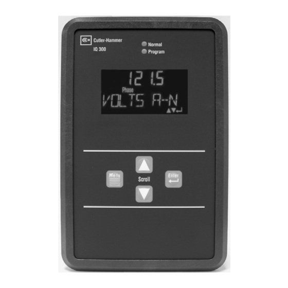
- Page 1 INSTRUCTION IQ 300 SERIES LEAFLET INSTRUCTIONS FOR INSTALLATION, IL17574C OPERATION AND MAINTENANCE OF THE CUTLER-HAMMER IQ 300 SERIES OF ELECTRICAL DISTRIBUTION SYSTEM METERS IL17574C Effective 2/04 For more information visit: www.cutler-hammer.eaton.com...
-
Page 2: Table Of Contents
3.3.1 Wiring System Current and Voltage ........ 3-7 3.3.2 Wiring Diagrams for Various System Configurations ..3-7 3.3.3 PowerNet Communications (IQ 320 and IQ 330 Base Modules Only) ................ 3-13 Page ii Effective Date: 2/04 For more information visit: www.cutler-hammer.eaton.com... - Page 3 4.10.3 MODBUS™ Setup (IQ 330M Base Module only) ..4-20 4.10.4 System Frequency ............4-21 4.10.5 Wiring Configuration ............ 4-21 4.10.6 CT Ratio ..............4-21 4.10.7 PT Ratio ..............4-22 Effective Date: 2/04 Page iii For more information visit: www.cutler-hammer.eaton.com...
- Page 4 6.2.1 General Safety Precautions ..........6-2 6.2.2 IQ 300 Base Module ............6-2 6.2.3 IQ 300 Display Module ............ 6-2 6.3 GENERAL TROUBLESHOOTING PROCEDURES ......6-3 6.4 TECHNICAL ASSISTANCE ..............6-5 Page iv Effective Date: 2/04 For more information visit: www.cutler-hammer.eaton.com...
-
Page 5: Section 1: Introduction
COMPLETELY READ AND UNDERSTAND THE MATERIAL PRESENTED IN THIS DOCUMENT BEFORE ATTEMPTING TO INSTALL, OPERATE OR USE THE EQUIPMENT. IN ADDITION, ONLY QUALIFIED PERSONS SHOULD BE PERMITTED TO PERFORM ANY WORK ASSOCIATED WITH Effective Date: 2/04 Page 1-1 For more information visit: www.cutler-hammer.eaton.com... -
Page 6: Factory Correspondence
220 / 380 Vac 120 / 240 Vac 480 Y / 277 Vac 480 Vac 230 / 400 Vac 600 Y / 347 Vac 600 Vac 240 / 415 Vac Page 1-2 Effective Date: 2/04 For more information visit: www.cutler-hammer.eaton.com... - Page 7 (that occur as often as 8ms) and 1 analog input to read 4 to 20 ma signal and display a percentage of 0 to 100. While the IQ 330M includes everything the IQ 330 Base Module includes, the INCOM communication is replaced with MODBUS. Effective Date: 2/04 Page 1-3 For more information visit: www.cutler-hammer.eaton.com...
- Page 8 Voltage var Hours Watts System Apparent Power Factor VA Hours vars System Displacement Power Factor Demand (W, var, VA) Peak Demand Apparent Power (W, var, VA) Factor Displacement Power Factor Page 1-4 Effective Date: 2/04 For more information visit: www.cutler-hammer.eaton.com...
-
Page 9: Section 2: Hardware Description
This lock out feature will not allow a user to change these settings until the lock out feature is turned off. See Section 4.6.4 for additional information about the lock out features. Effective Date: 2/04 Page 2-1 For more information visit: www.cutler-hammer.eaton.com... - Page 10 IL17574C IQ 300 Page 2-2 Effective Date: 2/04 Figure 2.2 IQ 310 Base Module Figure 2.2 IQ 320 Base Module Figure 2.2 IQ 330 Base Module Page 2-2 Effective Date: 2/04 For more information visit: www.cutler-hammer.eaton.com...
-
Page 11: Installation
IQ 300 Display Module. 2.3 BASE MODULE REAR ACCESS AREA All wiring connections are made from the rear face of the chassis, shown in figure 2.4a, 2.4b and 2.4c. Effective Date: 2/04 Page 2-3 For more information visit: www.cutler-hammer.eaton.com... -
Page 12: Current And Voltage Inputs
IQ 200 Display IQ 200 Display Module Module Ground Lug Ground Lug System System Neutral Neutral Power Supply Power Supply Voltage Input Voltage Input Figure 2.4a IQ 310 Rear Face View Page 2-4 Effective Date: 2/04 For more information visit: www.cutler-hammer.eaton.com... - Page 13 Communication Transmit LED Transmit LED PS1 PS2 PS1 PS2 Ground Ground System System Neutral Neutral Power Power Voltage Voltage Supply Supply Input Input Figure 2.4c IQ 330 Rear Face View Effective Date: 2/04 Page 2-5 For more information visit: www.cutler-hammer.eaton.com...
- Page 14 Figure 2.4e IQ 230 Rear Face View (continued) WARNING THIS TERMINAL BLOCK MUST NEVER BE REMOVED WHILE THE UNIT IS ENERGIZED. PERSONAL INJURY AND / OR EQUIPMENT DAMAGE MAY RESULT. Page 2-6 Effective Date: 2/04 For more information visit: www.cutler-hammer.eaton.com...
-
Page 15: Power Supply Input
When connected to a PowerNet System, via the INCOM port, it can be remotely monitored and functionally modified. PowerNet enables efficient monitoring, trending and alarm indication for electrical Effective Date: 2/04 Page 2-7 For more information visit: www.cutler-hammer.eaton.com... -
Page 16: Modbus Communications
IQ 300 Base Module as detailed in section 3.3. 2.4.3 External Fuses It is recommended that user-supplied fuses be installed as described below to protect the IQ 300 and related components from damage. Page 2-8 Effective Date: 2/04 For more information visit: www.cutler-hammer.eaton.com... -
Page 17: Product Specifications
Conducted Immunity EN61000-4-6 (1999) / EN61000-6-2 (1999) 10Vrms Power Frequency Magnetic Field EN61000-4-8 (1995) / EN62000-6-2 (1999) 30 A/m Surge Voltage EN61000-4-5 / EN61000-6-2 (1999) Voltage Dips EN61000-4-11 / EN61000-6-2 (1999) Effective Date: 2/04 Page 2-9 For more information visit: www.cutler-hammer.eaton.com... - Page 18 Digital Output (IQ 330 only) 125 Vac/176 Vdc Maximum Input Voltage Maximum Current Rating 96 mA 3750 V Input/Output Isolation Voltage Transient Overvoltage Category OVERVOLTAGE CATEGORY III Pollution Degree 2 (IEC 664) Page 2-10 Effective Date: 2/04 For more information visit: www.cutler-hammer.eaton.com...
- Page 19 ANSI C12 Note: The IQ 300 has been designed and verified to meet ANSI C12 Class 10 Revenue metering accuracy. This classification makes the IQ 300 an ideal choice for sub-metering and sub-billing applications. Effective Date: 2/04 Page 2-11 For more information visit: www.cutler-hammer.eaton.com...
- Page 20 9 in.-lbs. Maximum Distance Between Barriers 0.32 in. Weight Display Module 0.56 lbs. Base Module 2.35 lbs. includes 0.35 in. connector includes 0.62 in. terminal block centered on front face mounting plate Page 2-12 Effective Date: 2/04 For more information visit: www.cutler-hammer.eaton.com...
- Page 21 #16-28 AWG Torque Rating .22 - .25 Nm PS1 PS2 Base Unit Terminals Wire Size #12-22 AWG Screw Size #6-32 Torque Rating 9 in.-lbs. Maximum Distance Between Barriers 0.32 in. Effective Date: 2/04 Page 2-13 For more information visit: www.cutler-hammer.eaton.com...
-
Page 22: Ordering Information
(4) #10 Locking Washers Washers Washers Washers (2) ¼” #8 (8-32) (2) ¼” #8 (8-32) screws (4) #8 Hex Nuts (2) ¼” #8 (8-32) screws (2) Plug-in Contacts screws (2) Plug-in Contacts Page 2-14 Effective Date: 2/04 For more information visit: www.cutler-hammer.eaton.com... -
Page 23: Section 3: Installation
Display Module Chassis must be connected to earth ground. Before installing the IQ 300, refer to dimensions listed in table 2.5 and allow ad- equate room for wiring and access to the IQ 300 Base Module terminals and Effective Date: 2/04 Page 3-1 For more information visit: www.cutler-hammer.eaton.com... -
Page 24: Mounting The Iq 300 Modules As A Single Unit
Figure 3.1 Mounting Holes for the IQ 300 Display Module Page 3-2 Effective Date: 2/04 For more information visit: www.cutler-hammer.eaton.com... - Page 25 0 and +0.050 in. Normal Program IQ 300 Menu Enter Scroll Figure 3.2 Dimension on the IQ 300 Display Module Effective Date: 2/04 Page 3-3 For more information visit: www.cutler-hammer.eaton.com...
-
Page 26: Mounting The Iq 300 Display And Base Modules Separately
Module, the supplied L bracket, or the DIN clip to secure the IQ 300 Base Module in the desired location and orientation. Typical mounting options are shown in figure 3.4. The hole drilling pattern for mounting the IQ 300 Base Module to floor, wall or Page 3-4 Effective Date: 2/04 For more information visit: www.cutler-hammer.eaton.com... - Page 27 300 Display Module. Do not route the Category 5 cable in the same enclosure or cable tray as 600V system wiring. Figure 3.4 Typical Mounting Options for Mounting the IQ 300 Base Module Effective Date: 2/04 Page 3-5 For more information visit: www.cutler-hammer.eaton.com...
-
Page 28: Wiring
IQ 300 Display Module and the IQ 300 Base Module case must be connected to earth ground. If mounted together as one unit, the case of the IQ 300 Base Module must be connected to earth ground. Page 3-6 Effective Date: 2/04 For more information visit: www.cutler-hammer.eaton.com... -
Page 29: Wiring System Current And Voltage
This warning applies with reference to the current connector. WARNING THE IQ 330 AND IQ 330M TERMINAL BLOCK (FIGURE 2.4d) MUST NEVER BE REMOVED WHILE THE UNIT IS ENERGIZED. PERSONAL INJURY AND / OR EQUIPMENT DAMAGE MAY RESULT. Effective Date: 2/04 Page 3-7 For more information visit: www.cutler-hammer.eaton.com... - Page 30 VA VB VC NEU PS1 PS2 connected for proper operation FUSE IQ 320/IQ 230 IQ 310 90-600VAC 110-240VAC Control Power 48-250VDC 125-250VDC Figure 3.6 3 Phase 3 Wire Configuration (Above 600 Volts) Page 3-8 Effective Date: 2/04 For more information visit: www.cutler-hammer.eaton.com...
- Page 31 VA VB VC NEU PS1 PS2 connected for proper operation FUSE IQ 320/IQ 330 IQ 310 90-600VAC 110-240VAC Control Power 48-250VDC 125-250VDC Figure: 3.8 3 Phase 3 Wire, 2CT Configuration (Above 600 Volts) Effective Date: 2/04 Page 3-9 For more information visit: www.cutler-hammer.eaton.com...
- Page 32 PS1 PS2 connected for proper operation FUSE IQ 320 IQ 330 IQ 310 90-600VAC 110-240VAC Control Power 48-250VD C 125-250VD C Figure 3.10 3 Phase 4 Wire Configuration (Above 600 Volts) Page 3-10 Effective Date: 2/04 For more information visit: www.cutler-hammer.eaton.com...
- Page 33 VA VB VC NEU PS1 PS2 connected for proper operation FUSE IQ 320/IQ 330 IQ 310 90-600VAC 110-240VAC Control Power 48-250VDC 125-250VDC Figure 3.12 Single Phase 2 Wire Configuration (Up to 600 Volts) Effective Date: 2/04 Page 3-11 For more information visit: www.cutler-hammer.eaton.com...
- Page 34 VA VB VC NEU PS1 PS2 connected for proper operation FUSE IQ 320/IQ 330 90-600VAC Control Power 48-250VDC Figure 3.14 Typical IQ 320/IQ 330 Line-Powered Configuration (Up to 600 Volts) Page 3-12 Effective Date: 2/04 For more information visit: www.cutler-hammer.eaton.com...
-
Page 35: Powernet Communications (Iq 320 And Iq 330 Base Modules Only)
CTs and PTs, the CT and PT ratios must be taken into account when specifying the energy per pulse value. An example of how to specify the energy per pulse value is given below. Effective Date: 2/04 Page 3-13 For more information visit: www.cutler-hammer.eaton.com... - Page 36 (1400/5) x (2/1) x 7; or 3,920 watthours per pulse ∆ T ∆ T Figure 3.15 2-Terminal (K-Y) Figure 3.16 3-Terminal (K-Y-Z) Configuration Configuration Page 3-14 Effective Date: 2/04 For more information visit: www.cutler-hammer.eaton.com...
-
Page 37: Inputs And Outputs (Iq 330 And Iq 330M Only)
125 Vac / 176 Vdc Maximum Current Rating: 96 mA Maximum Current Rating: 96 mA Input/Output Isolation Input/Output Isolation Voltage: Voltage: 3750 Vrms 3750 Vrms Figure 3.17 Inputs and Outputs Effective Date: 2/04 Page 3-15 For more information visit: www.cutler-hammer.eaton.com... - Page 38 IL17574C IQ 300 Page 3-16 Effective Date: 2/04 This page is left blank intentionally. Page 3-16 Effective Date: 2/04 For more information visit: www.cutler-hammer.eaton.com...
-
Page 39: Section 4: Operation
Phase and Max words will be displayed. The lower right corner of the display has 3 icons. The arrow is on when up is a valid path and Effective Date: 2/04 Page 4-1 For more information visit: www.cutler-hammer.eaton.com... -
Page 40: Buttons
Navigates the user through menu items and through system values to be displayed Enter Confirms the option, value or screen currently selected and also allows rapid movement through data screens. Page 4-2 Effective Date: 2/04 For more information visit: www.cutler-hammer.eaton.com... -
Page 41: Contrast
(lagging P F) P ower E ngineer c apacitiv e negative N egative (leading P F) The relationships among system power values are shown schematically in fig- ure 4.1. Effective Date: 2/04 Page 4-3 For more information visit: www.cutler-hammer.eaton.com... -
Page 42: Using The Operator Panel
Menu descriptions cover both 3 and 4 wire systems where appropriate. Note: The lagging or leading indicator and any signs may be the opposite of that shown in the sample screens. Page 4-4 Effective Date: 2/04 For more information visit: www.cutler-hammer.eaton.com... - Page 43 IQ 300 IL17574C Effective Date: 2/04 Page 4-5 System DATA Reset VALUES Phase DATA DISP SETIN Min Max DATA DIAGNOSTIC VIEW SETPT EXIT MENU EDIT SETPT Figure 4.2 Main Menu Effective Date: 2/04 Page 4-5 For more information visit: www.cutler-hammer.eaton.com...
-
Page 44: Main Menu Display For The Iq 300
TRY AGAIN message will appear. Simple unlock the IQ 330 to access these functions. • System Frequency • Wiring Configuration • CT Ratio • PT Ratio • Demand Window • KYZ Setup • Reset Peak Demand • Reset System Energy Page 4-6 Effective Date: 2/04 For more information visit: www.cutler-hammer.eaton.com... - Page 45 System LD KVARHR ENTER XXXXXX.XX XXXXXX.XX System ENTER ANALOG IN System ENTER LG KVARHR ENTER XXXXXX.XX System UNLOCKED System ENTER NET KVARHR XXXXXX.XX System NET KVAHRS Figure 4.3 System Data Effective Date: 2/04 Page 4-7 For more information visit: www.cutler-hammer.eaton.com...
-
Page 46: Phase Data Display Mode
XXXXXX.XX XXXXXX.XX Phase Phase Max Demand ENTER ENTER VOLTS C--A IB AMPS XXXXXX.XX XXXXXX.XX Phase Demand Phase Max Demand ENTER IA AMPS IC AMPS Figure 4.4 3 Wire Phase Display Page 4-8 Effective Date: 2/04 For more information visit: www.cutler-hammer.eaton.com... - Page 47 Phase Max Demand ENTER A DS PF LD Phase ENTER IC AMPS B KWATTS ENTER XXXXXX.XX Phase ENTER C KWATTS XXXXXX.XX Phase A KVARS Figure 4.5 4 Wire Phase Display Effective Date: 2/04 Page 4-9 For more information visit: www.cutler-hammer.eaton.com...
-
Page 48: Min/Max Data Display Mode
If the value is leading, LD will be displayed; if the value is lagging, LG will be displayed. See section 4.4 Displayed Sign Convention for additional information. Page 4-10 Effective Date: 2/04 For more information visit: www.cutler-hammer.eaton.com... - Page 49 ENTER KWATTS XXXXXX.XX System Min ENTER KVARS XXXXXX.XX System ENTER KVARS XXXXXX.XX System Min ENTER XXXXXX.XX System ENTER XXXXXX.XX System Min FREQ IN HZ Figure 4.6 3 Wire Min/Max Data Effective Date: 2/04 Page 4-11 For more information visit: www.cutler-hammer.eaton.com...
- Page 50 Phase Min ENTER XXXXXX.XX VOLTS C--A System ENTER XXXXXX.XX Phase ENTER XXXXXX.XX VOLTS C--A System Min FREQ IN HZ XXXXXX.XX Phase Min VOLTS A--N Figure 4.7 4 Wire Min/Max Data Page 4-12 Effective Date: 2/04 For more information visit: www.cutler-hammer.eaton.com...
-
Page 51: View Set Points (3 And 4 Wire Systems)
PHASE, MSG, VOLT or O A1 PHASE NULL, depending on your selection. FREQ IN HZ O A2 PHASE 3/4 WIRE TRIP VALUE CT RATIO\5 ENTER EXIT SMENU Figure 4.8 View Setpoints Effective Date: 2/04 Page 4-13 For more information visit: www.cutler-hammer.eaton.com... -
Page 52: Password Setup
IQ 330M. The baud rate and the address must be set to the values required by the MODBUS network for network communication to occur. The Modbus address should be limited by the user to 0FF (hexadecimal). Page 4-14 Effective Date: 2/04 For more information visit: www.cutler-hammer.eaton.com... -
Page 53: System Frequency
IQ 300. If the ratio displayed is not correct, proceed to section 4.10 Figure 4.18 PT Edit Set Points for additional information. Ratio Display Effective Date: 2/04 Page 4-15 For more information visit: www.cutler-hammer.eaton.com... -
Page 54: Demand Window
When in MESSAGE mode the relay will be open or closed depending on an external message received by the unit. O A1 PHASE O A2 PHASE Figure 4.23 Digital Figure 4.22 Digital Output A2 Output A1 Page 4-16 Effective Date: 2/04 For more information visit: www.cutler-hammer.eaton.com... -
Page 55: Exit
If the correct password is entered, or if the Password option is not enabled, the screens shown in figure 4.26 will be available. Use the scroll arrows to move through the screens. Effective Date: 2/04 Page 4-17 For more information visit: www.cutler-hammer.eaton.com... - Page 56 3/4 WIRE the following: NULL, CLR or SET (depending on your A1 PHS NUL selection). CT RATIO\5 A2 PHS NUL TRIP VALUE ENTER EXIT SMENU Figure 4.26 Edit Setpoints Page 4-18 Effective Date: 2/04 For more information visit: www.cutler-hammer.eaton.com...
-
Page 57: Password Setup
9600 or 1200 baud. When the desired choice is displayed, press Enter to lock in the selection. XXXX INCOM RATE INCOM ADDR Figure 4.27 Incom Figure 4.28 Incom Rate Display Address Display Effective Date: 2/04 Page 4-19 For more information visit: www.cutler-hammer.eaton.com... -
Page 58: Modbus™ Setup (Iq 330M Base Module Only)
If the procedure completes successfully, Download OK appears briefly. The display then returns to the previous screen. XXXX MODBUS RAT MODBUS ADD Figure 4.29 Figure 4.30 MODBUS MODBUS Rate Address Display Display Page 4-20 Effective Date: 2/04 For more information visit: www.cutler-hammer.eaton.com... -
Page 59: System Frequency
To specify the ratio of the current transformers being used with the IQ 300, press either of the Scroll arrows repeatedly to step through the choices individually, or press and hold either of the Scroll arrows to step through the choices rapidly. There Effective Date: 2/04 Page 4-21 For more information visit: www.cutler-hammer.eaton.com... -
Page 60: Ratio
Scroll up or down the Edit Menu until you reach the WINDOW MIN option, press the Enter button. This screen, shown in figure 4.35, displays the current value of the demand time Page 4-22 Effective Date: 2/04 For more information visit: www.cutler-hammer.eaton.com... -
Page 61: Kyz Setup (Iq 320 And Iq 330 Base Modules Only)
There are up to 32 choices from 1/32 to 100 displayed as follows: Note: Some rates are available only in the IQ 320 or IQ 330 firmware version 1.02 Effective Date: 2/04 Page 4-23 For more information visit: www.cutler-hammer.eaton.com... -
Page 62: Digital Output Setup (Iq 330 & Iq 330M Base Module Only)
A, B & C phases are sampled and a default value is selected from one of four: 120, 240, 480 or 575. From this point the Trip Value is determined by the Page 4-24 Effective Date: 2/04 For more information visit: www.cutler-hammer.eaton.com... -
Page 63: Message To Outputs A1 And A2 (Iq 330 & Iq 330M Base Module Only)
A Phase choice will not let you send a message to that output. A2 PHS NUL A1 PHS NUL Figure 4.40 Output Figure 4.41 Output A1 Message A2 Message Display Display Effective Date: 2/04 Page 4-25 For more information visit: www.cutler-hammer.eaton.com... -
Page 64: Exit
The IQ 300 also has the ability to scroll through every data item while the unit is not in use. To select this Scroll Mode option use the up or down arrow to scroll through Page 4-26 Effective Date: 2/04 For more information visit: www.cutler-hammer.eaton.com... - Page 65 ENTER Min Max Reset FREQ PF SURE > N Reset Reset ENTER COMM STATS SURE > N Reset Reset ENTER INPUTS SURE > N EXIT SMENU Figure 4.42 Reset Values Effective Date: 2/04 Page 4-27 For more information visit: www.cutler-hammer.eaton.com...
-
Page 66: Backlight
To exit out of the main menu options simply press the Menu button, or press the Enter button when the EXIT MENU screen is displayed, this will return you to the main data screen. Page 4-28 Effective Date: 2/04 For more information visit: www.cutler-hammer.eaton.com... -
Page 67: Section 5: Network Communication Protocols5-1
The contents of MODBUS registers are product objects (e.g. Ia – phase A current). There is a single register map for all Eaton | Cutler-Hammer IQ products. Conse- quently, the objects listed in the following tables are identical registers called out by the mMINT. - Page 68 3 ph (power) 182A power reactive 3 ph 182C apparent 3 ph 182E displacement 3 ph 1830 power factor apparent 1832 frequency freq 1834 K-factor K-factor 1836 THD factor THD factor 1838 Page 5-2 Effective Date: 2/04 For more information visit: www.cutler-hammer.eaton.com...
-
Page 69: Function Codes
Using the 04 MODBUS command you can read any block from table 5.1. The beginning address and the size of the block are the elements of the 04 command. Below is an example of message for retrieval of data. Effective Date: 2/04 Page 5-3 For more information visit: www.cutler-hammer.eaton.com... - Page 70 There are two locations that are not 32 bit signed integers, “status cause” and “product ID”. These two locations will give valid single register (two byte) response and respond in the following formate. Page 5-4 Effective Date: 2/04 For more information visit: www.cutler-hammer.eaton.com...
- Page 71 Energy Error Decimal RAM Error Decimal ROM Error Decimal Calibration Error Decimal External RAM Error Decimal Setpoint Error Decimal No Error Decimal Definition Primary Secondary Active Decimal Decimal Alarm Decimal Decimal Effective Date: 2/04 Page 5-5 For more information visit: www.cutler-hammer.eaton.com...
-
Page 72: Extended Communications Via Modbus
1's Complement of Slave Action Byte0 Register 425091 (6202 15 14 13 12 11 10 1's Complement of Slave Action Byte1 1's Complement of Slave Action Byte2 Figure 5.2 Control Product Data Format Page 5-6 Effective Date: 2/04 For more information visit: www.cutler-hammer.eaton.com... - Page 73 5.4. Starting Address Lo The types of ‘slave action’ request are defined below. Number of Registers Hi Number of Registers Lo Error Check (LRC or CRC) Effective Date: 2/04 Page 5-7 For more information visit: www.cutler-hammer.eaton.com...
- Page 74 Acknowledge energy reset Activate Relay Output #X (X = relay output number: 1 or 2) De-activate Relay Output #X (X = relay output number 1 or 2) Acknowledge Digital Input Reset Page 5-8 Effective Date: 2/04 For more information visit: www.cutler-hammer.eaton.com...
-
Page 75: Command Data Pass Through
The format of the data acquired by the IQ 330M from the pass through INCOM product query’s response is given in Figure 5.4 . Note that each INCOM response message contains a status byte which indicates its validity. Effective Date: 2/04 Page 5-9 For more information visit: www.cutler-hammer.eaton.com... - Page 76 Byte0 of INCOM Response Msg nn Register (424834 + (2 * nn)) 15 14 13 12 11 10 Byte1 of INCOM Response Msg nn Byte2 of INCOM Response Msg nn Page 5-10 Effective Date: 2/04 For more information visit: www.cutler-hammer.eaton.com...
- Page 77 Number of Points Hi command. Table 5.9 is an Number of Points Lo example. Error Check (LRC or CRC) Refer to IL 17384 Part B related to IQ 330 for additional information. Effective Date: 2/04 Page 5-11 For more information visit: www.cutler-hammer.eaton.com...
- Page 78 Field Name Example (Hex) Slave Address Function Byte Count Data Hi (Register 6100) Data Lo (Register 6100) Data Hi (Register 6106) Data Lo (Register 6106) Error Check (LRC or CRC) Page 5-12 Effective Date: 2/04 For more information visit: www.cutler-hammer.eaton.com...
- Page 79 Message 4 Byte 0 shows Output 1 in message mode and Output 2 in phase mode. A 02 hex in Message 4 Byte 2 shows a voltage trip value of 2%. Effective Date: 2/04 Page 5-13 For more information visit: www.cutler-hammer.eaton.com...
- Page 80 Message 5 Byte 1 don’t care Message 5 Byte 2 don’t care Message 6 Byte 0 Message 6 Byte 1 Message 6 Byte 2 Error Check (LRC or CRC) Page 5-14 Effective Date: 2/04 For more information visit: www.cutler-hammer.eaton.com...
- Page 81 00 = 4-wire, 10 & 01 = 3-wire, 11 = Single phase B4-6 Code Dmd Window Code Dmd Window 5 minute 25 minute 10 minute 30 minute 15 minute 45 minute 20 minute 60 minute Reserved = 0 Effective Date: 2/04 Page 5-15 For more information visit: www.cutler-hammer.eaton.com...
-
Page 82: Modbus Exception Codes
5.8 MODBUS EXCEPTION CODES You can expect the following exception codes from the unit in a modbus exception message. Exception Description Code (Hex) Invalid Function Invalid Register Invalid Data Partial Register Access Error Page 5-16 Effective Date: 2/04 For more information visit: www.cutler-hammer.eaton.com... -
Page 83: Section 6: Troubleshooting And Maintenance6-1
ELECTRICAL WIRING AND/OR PARTS WHERE THE HAZARD OF FATAL ELECTRIC SHOCK IS PRESENT. PERSONNEL MUST EXERCISE EXTREME CARE TO AVOID INJURY OR DEATH. ALWAYS DISCONNECT, LOCK OUT AND TAG THE CURRENT AND VOLTAGE SOURCES AND Effective Date: 2/04 Page 6-1 For more information visit: www.cutler-hammer.eaton.com... -
Page 84: General Safety Precautions
#10 screws that secure the Base to the mounting brackets. • Grasp the IQ 300 Display Module to prevent it from falling and remove the hex nuts and washers that secure the mounting brackets, gasket and Display Module to Page 6-2 Effective Date: 2/04 For more information visit: www.cutler-hammer.eaton.com... -
Page 85: General Troubleshooting Procedures
If following this general troubleshooting guide fails to correct the malfunction, contact the plant maintenance department or contact Cutler-Hammer Power Management Applications Support (PMAS) at 1-800-809-2772, option 1 / option 1. You can also e-mail PMAS at pmpapps@eaton.com Effective Date: 2/04 Page 6-3 For more information visit: www.cutler-hammer.eaton.com... - Page 86 R e d u c e M o d b u s c o m m u n ic a tio n s , c o m m u n ic a tio n s re fe r to S e c tio n 3 .3 .5 Page 6-4 Effective Date: 2/04 For more information visit: www.cutler-hammer.eaton.com...
-
Page 87: Technical Assistance
Power Management Applications Support at 1-800-809-2772, option 1 / option 1 (outside the United States please call 1-414-449-7100 option 1 / option 1). You can also e-mail us at pmpapps@eaton.com or visit us on the web www.cutler-hammer.eaton.com and follow the power management products link. - Page 88 Cutler-Hammer business unit 1000 Cherrington Parkway Moon Township, PA 15108-4312 www.cutler-hammer.eaton.com IL17574C / Style #66A2087H04 For additional information please call: Power Management Products Center 1-800-809-2772 option 1 / option 1 © 2004 Eaton Corporation All Rights Reserved Publication No. IL17574C 2/04...
Need help?
Do you have a question about the Cutler-Hammer IQ 300 Series and is the answer not in the manual?
Questions and answers