Advertisement
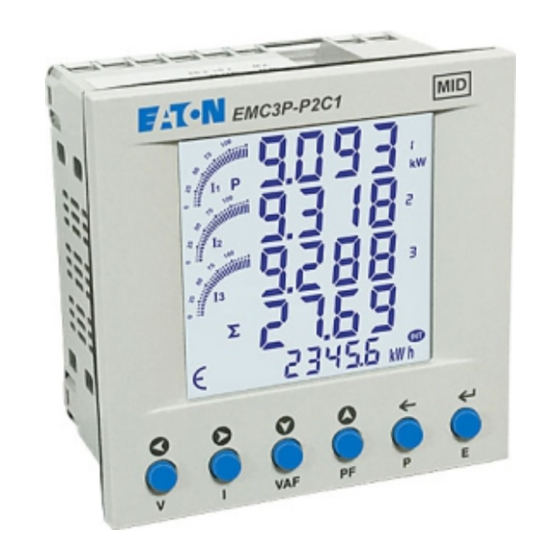
PRODUCT PROFILE
SPECIFICATIONS
Display
: Liquid crystal display with backlight 4 lines,
4 digits per line to show electrical Parameters
5th line, 8 digits to show energy Bar graph for
Current indication as percentage of CT rating
I
LCD Indications
:
PRG
Wiring Input
: 3 Ø - 4 wire, 1 Ø - 2 wire - P1, 3 Ø - 3 wire
Rated Input Voltage
: 3x230/400V
Installation Category
: III (300V L-N)
Frequency Range
: 47...63Hz (MID approved for 50Hz)
CT Primary
: 1/5A...6,000A (Programmable for any Value)
CT Secondary
: 1 or 5A (x1.2)
PT Primary
: 100V...600V (Programmable for any value)
PT Secondary
: 173...415V AC (L-L) (Programmable for any value)
Display Update Time : 1 second for all parameters
Display Scrolling
: Automatic / Manual
Auxiliary
: 85...270V AC, 47...63Hz
Temperature
: Operating : -10°C...55°C
Storage : -20°C...75°C
Humidity
: 85% non-condensing
Mounting
: Panel mounting
Meter Type
: Indoor
Weight
: 318gms
IP rating
: IP54 Front only (When fitted with rubber gasket)
Pulse Output
: External 5...27VDC max./100mA max.
Pulse Duration : Selectable 50...300mS
Pulse Resolution: Selectable 0.01...99.99kWh
Communications
: RS485 Modbus RTU
The meter is intended to be installed in Mechanical Environment `M1`,with
Shock and Vibrations of low significance, as per 2004/22/EC Directive.
The meter is intended to be installed in Electromagnetic Environment `E2`,
as per 2004/22/EC Directive.
ORDER INFORMATION
Outputs
Product
EMC3P-P2C1
Rs485 (Modbus RTU) & Pulse
SERIAL COMMUNICATION
Interface standard and protocol
Communication address
Transmission Mode
Data types
Transmission distance
Transmission speed
Parity
Stop bits
Response time
ACCURACY
Accuracy
Measurement
Voltage V
±0.5% of F.S.
L-N
Voltage V
±0.5% of F.S.
L-L
Current
±0.5% of F.S.
Frequency
For L-N > 20V,
±0.1% of F.S.
For L-L > 35V
Active Power
1%
Apparent power
1%
Reactive Power
1%
(F.S - Full Scale)
RI-F100-C
EMC3P-P2C1
96mm x 96mm
- Integration of energy
- Unit is in configuration menu
- Communication in progress
- Maximum & Minimum Demand of Power
Certification
RS485 AND MODBUS RTU
1...255
Half duplex
Float, Hex and Integer
500 Meter maximum
300, 600,1200, 2400, 4800, 9600,
19200 (in bps)
None, Odd, Even
1 or 2
100 ms
(max and independent of baud rate)
Accuracy
Measurement
±
Power factor
0.01 (Digit)
Active energy
EN50470-3: CI.B
Reactive energy
EN62053-23: CI.2
Apparent energy
Class 1
MAX/MIN
1%
Active Power
MAX/MIN
1%
Reactive Power
MAX Apparent Power
1%
Doc. name : OP INST EMC3P-P2C1
NOTE :
TO COMPLY WITH MID CERTIFICATION
THE CT RATIO MUST BE SET BEFORE
PUTTING THE METER INTO SERVICE
CONFIGURATION LOCK PARAMETER DESCRIPTION
NOTE:
Once Programming Mode Is entered The parameters
below will be locked out after 15 Minutes. No further
adjustment is possible without returning to supplier.
Network Selection
CT Primary
CT Secondary
PT Primary
Energy Reset
RESOLUTION
PT Ratio x CT Ratio
<15
<150
Note:
I
blinks every 5 sec. This indicates energy is being consumed.
SAFETY PRECAUTIONS
Safety related notifications, symbols and instructions that appear in this
operating manual or on the equipment must be strictly followed to ensure the
safety of personnel as well as the instrument.
If the equipment is not used in a manner specified by the manufacturer it may
impair the protection provided by the equipment.
Do not use the equipment if there is any mechanical damage.
Ensure that the equipment is supplied with correct voltage.
No repairs, maintenance or adjustments are possible.
CAUTION
1. Read complete instructions prior to installation or operation of the unit.
2. Risk of electric shock. Only to be installed by competent personnel.
3. The equipment in its installed state must not come in close proximity to any
heating sources, oils, steam, caustic vapors or other unwanted process
by-products.
WIRING GUIDELINES
1. To prevent the risk of electrocution, always isolate the power supply to the
equipment prior to undertaking any work. Always confirm absence of
supply prior to starting work using appropriate voltage detection
equipment.
MID
2. Wiring shall be done strictly according to the terminal layout. Confirm that
all connections are correct before energizing the equipment.
3. To reduce electromagnetic interference use of wires with adequate
ratings and twists of equal size are recommended. All connection should be
kept as short as possible.
4. Routing of connecting cables shall be away from any internal EMI source.
5.All cables used for connections must have a cross section
2
of 0.5mm to 2.5mm . (20 to14AWG ; 75 C (min) )
6. Copper cable should be used. (stranded or solid core cable)
7. All wiring to be in accordance with applicable local standards.
CURRENT CONNECTION INDICATION
Press I key for 3 sec. to check the current connection. If current connection
reverse meter will show in which phase connection is reversed.
0 - No any phase
1 - 1st phase
DEVICE IDENTIFICATION
Press PF key for 10 sec, displays CRC in first two row, HW & SW version no
in 3rd and 4th raw & serial no in last row.
AUTOMATIC / MANUAL PAGE SCROLLING
Press E (
) button for 3 seconds to toggle between Automatic and Manual
mode.
Note : By default unit operates in automatic mode.
In automatic mode online pages scroll automatically at the rate of 5
seconds per page. All the time, total import active energy will be displays &
at any other page of energy if no key is pressed for 1 min.
In automatic mode when any key is pressed, unit temporarily switches to
manual mode and the appropriate page is displayed, also if no key is
pressed for 5 sec, unit resumes automatic mode.
PT secondary
Pulse width
Pulse Duration
Factory default
kWh
<1500
0.01K
<15000
0.1K
>15000
2
0
2 - 2nd phase
3 - 3rd phase
OP532-EMC3P-P2C1-V01-EATON (Page 1 of 6)
1K
0.01M
0.1M
Advertisement
Table of Contents

Related Manuals for Eaton EMC3P-P2C1


Summary of Contents for Eaton EMC3P-P2C1
- Page 1 MAX Apparent Power Reactive Power pressed for 5 sec, unit resumes automatic mode. Doc. name : OP INST EMC3P-P2C1 OP532-EMC3P-P2C1-V01-EATON (Page 1 of 6) (F.S - Full Scale)
-
Page 2: Front Panel Description
“VAF” The fourth screen : Displays average value of voltage, current and We, Eaton Electric GmbH., declare under our sole responsibility as the power factor of three phases and frequency. manufacturer that the EMC3P-P2C1 meter described within this manual Note : 1)In 3 Ø... -
Page 3: Programming Menu
No / Yes Reset Reactive Energy 20.02 No / Yes Pulse output from EMC3P-P2C1 meter can be interfaced into a process Reset Apparent Energy 20.03 No / Yes through a PLC for on line control of energy content in the process. - Page 4 Eg. {143 + [(14-2) x 2 ] + 60 x 5} = 467 Voltage V12 Current I3 Voltage V23 So, Check the 14 Harmonic of Voltage V31 at 467 address. Doc. name : OP INST EMC3P-P2C1 OP532-EMC3P-P2C1-V01-EATON (Page 4 of 6)
- Page 5 IMP Kvarh1 RC* 31221 Total Net Kvarh RC* 31206 Toatl IMP Kwh RC* 31214 IMP Kvarh2 RC* NOTE : : Rollover counter 31207 Total EXP Kwh RC* 31215 IMP Kvarh3 RC* Doc. name : OP INST EMC3P-P2C1 OP532-EMC3P-P2C1-V01-EATON (Page 5 of 6)
-
Page 6: Typical Wiring Diagram
(Specifications are subject to change, since development is a continuous process.) Network selection in configuration mode Wiring Eaton Industries (Austria) GmbH, Eugenia 1, A-3943, Schrems, Austria 3P4W 3P4W Website: www.eaton.com/meter Support: techsupportemea@eaton.com 3P3W 3P3W www.eaton.com/recycling 1P2W 1P2W-P1 Doc. name : OP INST EMC3P-P2C1 OP532-EMC3P-P2C1-V01-EATON (Page 6 of 6)
Need help?
Do you have a question about the EMC3P-P2C1 and is the answer not in the manual?
Questions and answers