Table of Contents
Advertisement
Quick Links
ELECTRICAL
TM
InsulGard
USER'S MANUAL
©
EEPD, 2002, 2003, 2004, 2005
Version 2-0X
Revision 1.1
(December 2005)
PREDICTIVE DIAGNOSTICS DIVISION
5421 Feltl Road, Ste 190, Minnetonka, MN 55343
Phone (952) 912-1331 or -1358, Fax (952) 912-1355;
Web-site: www.partial-discharge.com; e-mail: chpd@eaton.com
Advertisement
Table of Contents

Related Manuals for Eaton InsulGard


Summary of Contents for Eaton InsulGard
- Page 1 ELECTRICAL InsulGard USER’S MANUAL © EEPD, 2002, 2003, 2004, 2005 Version 2-0X Revision 1.1 (December 2005) PREDICTIVE DIAGNOSTICS DIVISION 5421 Feltl Road, Ste 190, Minnetonka, MN 55343 Phone (952) 912-1331 or -1358, Fax (952) 912-1355; Web-site: www.partial-discharge.com; e-mail: chpd@eaton.com...
-
Page 2: Table Of Contents
Noise Aspects....................17 2.1.4 Device Location and Environmental Issues............17 2.1.5 What Additional Parameters to Measure?............17 2.1.6 Networking and Communicating with InsulGard..........18 2.1.7 Application Specific for Motors and Small Generators........18 2.1.8 Application Specific for Large Generators ............19 2.1.9 Application Specific for MV Switchgear ..............20 Installation .........................20... - Page 3 6.1.2 Revision 1 ......................56 Phase Reference Shift....................57 6.2.1 Internal Synchronization..................57 6.2.2 External synchronization ..................59 Auxiliary input configuration ..................60 Appendix 3. Temperature Channel Calibration ............61 EATON ELECTRICAL Predictive Diagnostics...
- Page 4 ТМ What is new in InsulGard Firmware version 2.0X Starting from July, 2004 new firmware version 2.0X is preloaded in InsulGard monitor. This updated manual is applicable to old firmware version and states the difference where necessary. The following table describes major differences between the version 2.0X and all previous versions.
- Page 5 IG during start up. All necessary commutations are done with additional switch located at the bottom of sensor interface board. InsulGard , revision 1 can be identified by the presence of described switch or by a wiring diagram identification label located on power outlet panel. The label looks...
-
Page 6: Description
It measures partial discharges from up to 15 different partial discharge sensors and stores the information in internal memory; alarming users if any set points are exceeded. InsulGard can work with constant 50/60 Hz frequency powered equipment as well as with variable frequency applications. -
Page 7: Principles Of Operation
(Ch16). All sixteen inputs have identical conditioning circuits (CC) providing signal isolation, transient suppression, and high- pass filtering of the input signals. The frequency band of the InsulGard is from 1 MHz to 20 MHz. -
Page 8: Important Features And Options
LEDs (Normal condition, Red and Yellow alarms, and 5 LEDs History and Setting modes) Setup Fully configurable from keypad and PC For another rating refer to the relay specification For another rating refer to the relay specification EATON ELECTRICAL Predictive Diagnostics... -
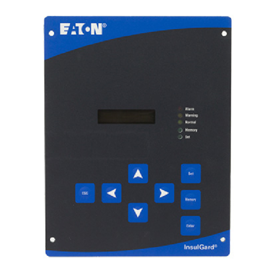
Page 9: Display, Keypad, And External Connections
RG-58 or similar 1.3.2 Display, Keypad, and External Connections InsulGard is shipped fully assembled in NEMA4 (4X) enclosure, mounted on aluminum plate with selected communication options or in panel-mount version. These options may include RS485/RS232 converter (Figure 2), landline (Figure 1 & 3) or cellular modem, radio-modem (Figure 2). - Page 10 Display LED: 3 – alarms 1 – Memory mode 1 - Set Keypad Figure 1 Radio-modem RS485/RS232 Converter InsulGard. Back view Sensor Interface Board Flat ribbon cable PD signal to sensor connection interface board Auxiliary signal Terminal board for outputs and...
-
Page 11: Data Structure
Figure 3 1.3.3 Data Structure Full PD measurement by InsulGard involves a measurement of statistical Phase Resolved Partial Discharge Distribution (PRPDD) for every active channel. After each measurement for every active channel, InsulGard calculates PDI, Maximum PD magnitude, PD pulse repetition rate, and trend parameters (rate of PD parameter change). -
Page 12: Alarms
Yellow and Red alarms operate differently. In the case of a Yellow alarm, it will appear on the corresponding relay as received. In the case of a Red alarm, InsulGard will initiate an additional measurement at the time of alarm, and only if confirmed, will indicate the alarm by relay. -
Page 13: Continuous Watch Feature
There are two options of supplying the synchronization: • In most of cases power source (120/230 VAC) powering up InsulGard is used as a synchronization signal. The device has the internal connection of the power circuit voltage to its synchronization circuitry. -
Page 14: Device Address And Communication Options
PD characteristics. InsulGard has three auxiliary inputs. One of the inputs is strictly designated for temperature. 10, 100, and 1000 Ohms RTD can be used as a sensor. This setting is factory configured and should be specified at the time of device ordering. -
Page 15: Measurement Suspend
1.3.15 Software InsulGard comes with Database InsulGard software that allows it to communicate with a PC via a local RS-485 network or a modem. It also provides automated or manual data downloading and storage for several devices at different locations, device setting, data analysis, and presentation. -
Page 16: Installation
2 Installation Application Issues InsulGard is a versatile device that can be applied to most medium voltage equipment. Specifics of a particular application (optional components and planning installation) should be taken into account when ordering. Issues that should be considered are: •... -
Page 17: Noise Aspects
(given a relatively clean environment). In most applications, indoor and outdoor, InsulGard is contained in a NEMA-4 enclosure protecting the device from direct rain, sun, and dust. If the application environment is a chemically aggressive medium, or a company policy requires a stainless steel enclosure (NEMA-4X), please, specify this while ordering InsulGard. -
Page 18: Networking And Communicating With Insulgard
2.1.6 Networking and Communicating with InsulGard InsulGard provides several interfaces for alarms, SCADA, and data retransmission • Always wire alarm relays to an annunciation system. Use two relays for Red and Yellow alarm and the third relay for device status. -
Page 19: Application Specific For Large Generators
It does not affect temperature measurements, and produces PD signals for InsulGard. RTD PD board is designed to handle six RTDs. If, in a particular application, the number of RTDs is greater than 6, additional boards might be needed. -
Page 20: Application Specific For Mv Switchgear
T-connection. IPDS can be installed on a bus side or load side of a breaker. In the case of a load side, the sensor will not measure PD while the breaker is open. In general, one InsulGard can handle up to 15 cubicles. -
Page 21: Important Note On Sensor Installation In Rotating Machines
End-user should install InsulGard and communication means at a convenient location(s). 2.2.1 Important Note on Sensor Installation in Rotating Machines InsulGard software has several useful configuration templates allowing simple configuration a majority of standard applications. These templates for rotating machines assume that all coupling capacitors connected sequentially to first IG channels in sequences of A-B-C. -
Page 22: Insulgard Kit Contents
2.2.2 InsulGard Kit Contents Item Description Included/Optional Quantity Comments InsulGard Device with: Included • Sensor Interface Board, • 44 wire ribbon cable, • Terminals for outputs connection. NEMA-4 enclosure and/or mounting panel Included if not a flash mount option 115VAC, 10 A receptacle... - Page 23 Stock # 216-2740 (20AWG), by BELDEN Mfr’s #9364 3.2.3. Stock # 216-2666 (18AWG), by BELDEN Mfr’s #1036A You may also order these cables to CHPD. 115V AC power cable 3-wire (11 Amps). OD should not exceed 0.40”. EATON ELECTRICAL Predictive Diagnostics...
-
Page 24: Installation
Step 1 – Hardware (This paragraph covers main guide-line. Chosen InsulGard options must be taken into account in every particular case.) • Select a convenient location for an InsulGard enclosure. It should be as close as possible to the equipment being monitored. - Page 25 2.2.3.3 Step 3. - Connections to the device. All signal connections inside the InsulGard enclosure are found on the Sensor Interface Board shown in Figure 4. Connectors are in red on in the Figure 5. WARNING: THIS MONITOR MUST BE INSTALLED AND SHOULD NOT BE USED FOR ANY OTHER PURPOSE THAN WHAT IS DESCRIBED IN THIS DOCUMENT.
- Page 26 The 40-pin connector TB2 (top left) serves the connection between the Sensor Interface Board and the InsulGard device via a flat ribbon cable included with the kit. The 12- terminal strip TB3 (bottom left) serves all auxiliary signal connections, such as temperature, current, humidity, and voltage.
- Page 27 Humidity Sensor common wire +5 Volt for humidity sensor Same For H% sensor only Humidity sensor signal wire Same For H% sensor only Panel Terminal Strip Pre-Revision 1 Revision 1 Note G - External AC power Ground Same EATON ELECTRICAL Predictive Diagnostics...
- Page 28 Figures 6.1 (Pre-Revision 1) and 6.2 (Revision 1) give typical connection diagram for panel mount IG option. These are samples only! Actual wiring diagram is ALWAYS delivered with a device and MUST be used for connections! EATON ELECTRICAL Predictive Diagnostics...
- Page 29 5. FUSES: Miniature Fuses 5x20, 250VAC, 195 Series by Wickmann ( Distributor - DigiKey.com). Fuse inside Insulgard for 120V application - 200mA ( DigiKey Part NO: WK5034-ND), for 230VAC application - 80mA ( DigiKey Part NO: WK5026-ND). Fuse on a panel: 1.0A (DigiKey Part NO: WK5048-ND).
- Page 30 (Alarm1&2, R3) and use a right hub for all signal cables. 4. FUSES: Miniature Fuses 5x20, 250VAC, 195 Series by Wickmann ( Distributor - DigiKey.com). Fuse inside Insulgard for 120V application - 80mA ( DigiKey Part NO: WK5026-ND), Fuse on the panel: 1.0A (DigiKey Part NO: WK5048-ND).
- Page 31 AC). Check the resistance between respective RTD terminals of TB-3 terminal board. • Check that the flat ribbon cable is connected to InsulGard inside its enclosure. Make sure that all connector latches are in vertical position (locked). • Install InsulGard and fasten it to the standoffs with the supplied screws.
- Page 32 InsulGard, plug the cord from the power module into an outside 115 V AC receptacle. Power and TR LED should be on. The modem is ready for communication.
-
Page 33: Startup
The sequence of the steps is most optimal. Try to follow the sequence. Once InsulGard is installed, all signals are connected and equipment is powered up, What are the most critical parameters to at commissioning? The following description attempts to present an order of the device setting. For full... - Page 34 The following procedure assumes the most difficult manual setup. If set from a PC, many settings can be combined into one setup command. Refer to “InsulGard Software Manual”. You can print the following table below and check that the procedures are completed.
- Page 35 Press Enter when finished with selected channel. Using select another channel. the same sensitivity. Recommended sensitivity, if unknown, is in Press Esc when done for all channels. parentheses: EATON ELECTRICAL Predictive Diagnostics...
- Page 36 Power Frequency - (FrEQ) Temperature - (Fr06) Voltage - (Fr07) Current - (Fr08) Scroll setup parameters until SHt appears. Press Enter. SHt-03 will appear. keys to set desired scroll time between the displayed items (seconds). When done, press Enter. EATON ELECTRICAL Predictive Diagnostics...
- Page 37 Scroll setup parameters until CALibr I appears. Repeat the same procedures as for the voltage When done, press Enter. Activate There is an option to use Current, Voltage, Temperature Scroll setup parameters until InPt or InPI or InPU appears. EATON ELECTRICAL Predictive Diagnostics...
- Page 38 1. IG displayed dashes for several times in the Connections for automatic detection of phase shift in Pre-Revision 1: versions 2.00 and higher (bad phase reference signal) Humidity sensor wires (or jumper wire between terminals 10 and 12 • EATON ELECTRICAL Predictive Diagnostics...
- Page 39 This result should be entered in manual mode. Example: Reference signal from A-B phase (open delta PT) is used. Automatically detected phase shift is . Adding +30 = 375 . Subtracting 360 = +15 . 15 EATON ELECTRICAL Predictive Diagnostics...
- Page 40 In case On or OFF was selected, the setting will be stored. In case t was selected, t-0000 will appear. Using present set time for Enabled for Time (t) – Relay contacts will be closed relay closing in seconds. EATON ELECTRICAL Predictive Diagnostics...
- Page 41 MODBUS protocol. All earlier versions protocol support only RTU version. Using you may change protocol to tYPE tCP Press Enter. Exit Setup Press Esc and SAVinG will appear Check that results are reasonable! Start a Single Measurement EATON ELECTRICAL Predictive Diagnostics...
-
Page 42: Working With Data Memory
Working with Data Memory InsulGard allows observing all stored information in the memory data. ♦ Press the Memory key to enter memory mode. ♦ Device will display ALL-XXXXX - total number of records in its memory. ♦ Press Enter key. The current month and date will be displayed. -
Page 43: Troubleshooting
4 Troubleshooting Error Messages InsulGard performs various tests at powering up, before every measurement and in some more situations. In the case of a fault, an error message will be displayed and the status relay contacts will open. The error message on IG display will appear as follows: --Sync-- - Loss of synchronization signal. - Page 44 Replace fuse using appropriate fuse holder with new fuse. Check the old fuse, if it ♦ has been blown up. Assemble the device and make all connections; ♦ Check for correct connections and then power it up. ♦ EATON ELECTRICAL Predictive Diagnostics...
-
Page 45: Appendix 1. Device Setup Via Keypad
Time of next measurement - (rEAd) Scroll channels - (CHAn) (This option will scroll data for all active channels in terms of % of Red threshold and Alarm status.) Power Frequency - (FrEQ) Temperature - (Fr06) Voltage - (Fr07) EATON ELECTRICAL Predictive Diagnostics... - Page 46 When done, press Enter. See also Setting Scrolling Time. Sensor Sensitivity: InsulGard can use almost any PD sensor that is capable of operating in a radio-frequency band. Sensors differ by their response to the same discharge event, in other words, by their sensitivity. In order to take into account the specifics of a particular sensor, one should set proper sensitivity for every used sensor.
- Page 47 Alarm Status Thresholds for PDI and Magnitude (Q ) and Trend Thresholds: InsulGard operates Alarm contacts based on PD parameter LEVEL and TREND (rate of parameter change). Two PD parameters are available for alarm: PDI – partial discharge intensity and Q –...
- Page 48 (of 60 or 50 Hz) for the measurement. When done, press Enter. Alarm Relay Mode: Alarm Relay can be set in one of three modes: Disabled (OFF) – Relay will not close contacts in a case of alarm EATON ELECTRICAL Predictive Diagnostics...
- Page 49 When done, press Enter. Watch Function Settings: InsulGard has a Continuos Watch feature. This option is enabled between measurements and utilizes a separate counter. All PD signals are brought to this counter, which counts high level pulses and their series. If the device counts 5 series of high level pulses, it starts a regular measurement and, if Red alarm status is detected, stores FULL data and turns on the alarm.
- Page 50 This stops monitoring for indefinite time. To resume monitoring set control in STOP-no position. Setting Internal Phase Shift: By default, InsulGard uses the internal phase reference from its 115/230 VAC power source. (External phase reference is also available for specific applications such as, variable frequency drives (refer to the correspondent part of User Manual).
- Page 51 Phase Assigning to a Channel: As the InsulGard uses a variety of sensors that can be associated (directly or indirectly) with any phase (or their combination thereof) of the electrical system, it is important that each sensor be assigned to a correct phase.
- Page 52 (RTD) as a sensor. RTD can vary by type and resistance. If no other option is specified by the user at the time of ordering, InsulGard is supplied and calibrated for the Platinum (Pt) 100 Ohm RTD. Use of any other RTD type will require a hardware change and recalibration in the field.
- Page 53 ♦ Software Filters At the latest firmware versions of InsulGard software filters based of PD fingerprint analysis are became available. These filters have been specifically developed for coupling capacitor sensors on large turbine generators equipped with long iso-phase bus ducts. We do not recommend to use these filters in another equipment or sensors without consulting to an expert.
- Page 54 Press Enter. tYPE rtU will appear. ♦ Using you may change protocol to tYPE tCP ♦ Press Enter. ♦ Note: By pressing ESC at any time during scrolling setup parameters, the current settings will be saved. EATON ELECTRICAL Predictive Diagnostics...
-
Page 55: Appendix 2. Synchronization And Phase Reference Shift
InsulGard allows for external and internal synchronization from 115/230VAC power supply. The second is most reliable option and it is default for InsulGard. InsulGard stops operation only if power is off. External synchronization is used only when it is really necessary, if power supply voltage is not synchronous with the voltage on the monitored object. -
Page 56: Revision 1
6.1 (the figure 6.1) above, IG will be synchronized from PD sensor connected to the channel 1. Jumper J1 actually connects this input to synchronization circuitry. Refer to the figure 6.3 for jumper locations. EATON ELECTRICAL Predictive Diagnostics... -
Page 57: Phase Reference Shift
Phase Reference shift is a phase angle between IG synchronization signal and the phase A voltage on the monitored object. It does not matter how this number is obtained. One may use InsulGard, a phase meter, oscilloscope or another instrument. - Page 58 Note that input impedance is 1Mohm and a reference signal should not exceed 6AC. In case of PT signal is used and in order to protect both PT output and InsulGard input make simple resistive divider circuit made of 10kOhm and 100Ohm resistors.
-
Page 59: External Synchronization
#12 terminal input is a very sensitive and it has high impedance. It is affected by power frequency noise. Below are some hints that may identify incorrect phase angle measurement: InsulGard displays dashes with some consistency in firmware version 2.00 and higher or 0 in •... -
Page 60: Auxiliary Input Configuration
Auxiliary input configuration Fig.6.4 InsulGard accepts three additional signals for PD correlation to a dynamics. One signal is always a temperature. See the following paragraph for temperature channel configuration and calibration. Two another inputs are configurable for Load Current or Humidity (J4) and for System Voltage or Humidity (J5). -
Page 61: Appendix 3. Temperature Channel Calibration
InsulGard can be configured for 10Ohms, 100Ohms and 1000Ohms Pt RTDs. 120 Ohm Ni fits 100 Ohm Pt range. InsulGard is configured and calibrated at the factory for 100 Ohm Pt RTD, if other has not been specified. Reconfiguring temperature channel requires hardware jumpers’ configuration and calibration. Procedures are described below. - Page 62 2 and 3. Figure 2. sensor interface board must be connected to InsulGard with supplied ribbon cable and the device must be powered up. Enter setup mode by pressing “Set” key. PSd-____ will appear on the display. A correct password must be entered, in order to enter the setup mode.
Need help?
Do you have a question about the InsulGard and is the answer not in the manual?
Questions and answers