Eaton IQ 250 User & Installation Manual
Multifunction electricity meter
Hide thumbs
Also See for IQ 250:
- User & installation manual (143 pages) ,
- Quick start manual (2 pages) ,
- Instructional leaflet (13 pages)

Related Manuals for Eaton IQ 250


Summary of Contents for Eaton IQ 250
- Page 1 IQ 250/260 Low-Cost High Performance Multifunction Electricity Meter User & Installation Manual www.eaton.com IB02601006E Rev. 1.0...
-
Page 3: Table Of Contents
IQ 250/260 Meter Table of Contents 1 INTRODUCTION About this Manual Warranty and Liability Information Safety Precautions 2 IQ 250/260 Overview and Specifications IQ 250/260 Overview Voltage and Current Inputs Ordering Information Measured Values Utility Peak Demand Specifications Compliance Accuracy... - Page 4 Using Operating Mode 6-10 Understanding the % of Load Bar 6-11 Performing Watt-Hour Accuracy Testing (Verification) 6-12 7 Using the IQ 250/260 I/O Option Cards Overview Installing Option Cards Configuring Option Cards Digital Output (Relay Contact)/Digital Input Card Specifications Wiring Diagram Pulse Output (Solid State Relay Contacts)/Digital Input Card Specifications...
- Page 5 8-29 Viewing Option Card Information 8-29 Performing Manual Relay Control 8-30 Performing Firmware Flash Update 8-30 Performing Additional Tasks with IQ 250/260 Configuration Software 8-31 Using Connection Manager 8-31 Disconnecting from an IQ 250/260 8-33 Changing the Primary Device/Address 8-33...
- Page 6 Appendix B - Modbus Mapping for IQ 250/260 Introduction Modbus Register Map Sections Data Formats Floating Point Values Modbus Register Map (MM-1 to MM-8) Appendix C - Using DNP Mapping for IQ 250/260 Overview Physical Layer Data Link Layer Application Layer Error Reply...
-
Page 7: Introduction
This document is the user manual for the installation, operation, and maintenance of the Eaton IQ 250/260 Meter. It is intended for authorized and qualified personnel who use the IQ 250/260 Meter. Please refer to the specific WARNINGS and CAUTIONS in this section before proceeding. - Page 8 Follow all Warnings and Cautions. Completely read and understood the information in this document before attempting to install or operate the equipment. Improper wiring could cause death, injury, or equipment damage. Only qualified personnel are to service the IQ 250/260 Meter. TROUBLESHOOTING PROCEDURES MAY REQUIRE PROXIMITY TO EXPOSED ENERGIZED (LIVE) ELECTRICAL WIRING AND/OR PARTS WHERE THE HAZARD OF FATAL ELECTRIC SHOCK IS PRESENT.
-
Page 9: Iq 250/260 Overview
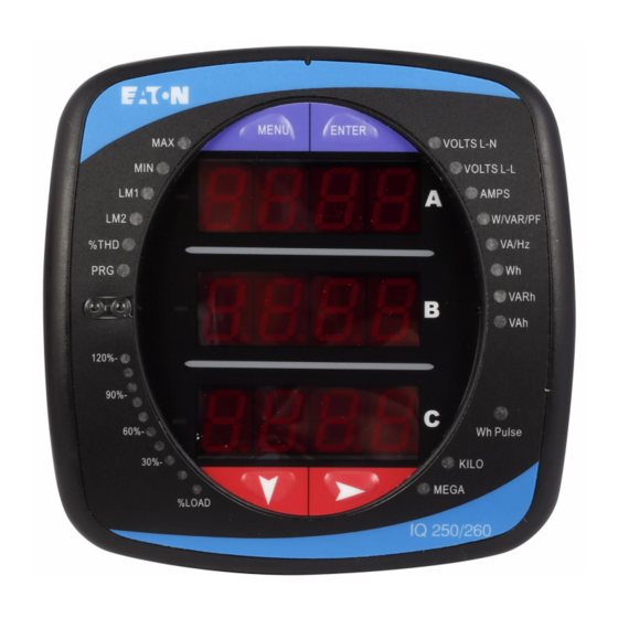
Figure 2.1: IQ 250/260 Meter The IQ 250/260 meter is designed with advanced meaurement capabilities, allowing it to achieve high performance accuracy. It is specified as a 0.2% class energy meter for billing applications as well as a highly accurate panel indication meter. -
Page 10: Voltage And Current Inputs
The unit supports a 5 amp or a 1 amp secondary for current measurements. NOTE: The secondary current must be specified and ordered with the meter. The IQ 250/260 Current Inputs use a unique dual input method: Method 1: CT Pass Through The CT passes directly through the meter without any physical termination on the meter. -
Page 11: Ordering Information
Chapter 2: IQ 250/260 Meter Overview and Specifications Ordering Information IQ - 260 - M - A - 6 - 5 - 1 - 1 - 0 1. Model: 250 = Power Meter 260 = Power Quality Meter 2. Meter Type... -
Page 12: Measured Values
Chapter 2: Overview and Specifications IQ 250/260 Meter Measured Values The IQ 250/260 provides the following Measured Values all in Real-Time Instantaneous, and some additionally as Average, Maximum and Minimum values. IQ 250/260 Measured Values Measured Values Instantaneous Voltage L-N... -
Page 13: Utility Peak Demand
Overview and Specifications Utility Peak Demand The IQ 250/260 provides user-configured Fixed Window or Sliding Window Demand modes. This feature enables you to set up a customized Demand profile. Fixed Window Demand mode records the average demand for time intervals that you define (usually 5, 15 or 30 minutes). - Page 14 Chapter 2: Overview and Specifications IQ 250/260 Meter KYZ/RS485 Port Specifications RS485 Transceiver; meets or exceeds EIA/TIA-485 Standard: Type: Two-wire, half duplex Min. Input Impedance: 96kΩ Max. Output Current: ±60mA Wh Pulse KYZ output contacts (and infrared LED light pulses through face plate): (See Chapter 6 for Kh values.)
- Page 15 Chapter 2: IQ 250/260 Meter Overview and Specifications Isolation All Inputs and Outputs are galvanically isolated to 2500 Vac Environmental Rating Storage: (-20 to +70) Operating: (-20 to +70) Humidity: to 95% RH Non-condensing Faceplate Rating: NEMA12 (Water Resistant), Mounting Gasket Included...
-
Page 16: Compliance
Chapter 2: Overview and Specifications IQ 250/260 Meter Compliance • UL Listing: USL/CNL E250818 • IEC 687 (0.2% Accuracy) • ANSI C12.20 (0.2% Accuracy) • • ANSI C62.41 (Burst) • I C12.2 • IEC 1000-4-2 - ESD • ANSI C62.41 to be supplied before document release Accuracy (See full Range specifications earlier in this chapter.) -
Page 17: Mechanical Installation
Mechanical Installation Introduction The IQ 250/260 meter can be installed using a standard ANSI C39.1 (4” Round) or an IEC 92mm DIN (Square) form. In new installations, simply use existing DIN or ANSI punches. For existing panels, pull out old analog meters and replace them with the IQ 250/260. - Page 18 Mechanical Installation IQ 250/260 Meter 0.95 [24.04] 3.25 [82.55] 0.77 [19.55] 3.54[89.92] 4.85 [123.19] 0.91 [23.11] 3.25 [82.55] 0.77[19.55] 3.54 [89.92] Fig. 3.4: IQ 250/260 Back Face Figure 3.5: ANSI Mounting Panel Cutou Figure 3.6: DIN Mounting Cutout IB02601006E www.eaton.com...
-
Page 19: Ansi Installation Steps
Chapter 3: IQ 250/260 Meter Mechanical Installation ANSI Installation Steps NEMA 12 Mounting Gasket Threaded Rods Lock Washer and Nut Figure 3.7: ANSI Mounting Procedure 1. Insert 4 threaded rods by hand into the back of meter. Twist until secure. -
Page 20: Din Installation Steps
Chapter 3: Mechanical Installation IQ 250/260 Meter DIN Installation Steps DIN Mounting Bracket Top Mounting Bracket Groove Bottom Mounting Bracket Groove #8 Screw IQ 250/260 Meter with NEMA 12 Mounting Gasket Remove (unscrew) ANSI Studs for DIN Installation Figure 3.8: DIN Mounting Procedure 1. -
Page 21: Iq 250/260T Transducer Installation
Chapter 3: IQ 250/260 Meter Mechanical Installation IQ 250/260T Transducer Installation The IQ 250/260T Transducer model is installed using DIN Rail Mounting. Specs for DIN Rail Mounting: International Standards DIN 46277/3 DIN Rail (Slotted) Dimensions: 0.297244” x 1.377953” x 3” (inches) 7.55mm x 35mm x 76.2mm (millimeters) - Page 22 Chapter 3: Mechanical Installation IQ 250/260 Meter IB02601006E www.eaton.com...
-
Page 23: Electrical Installation
Appropriate safety gloves, safety glasses and protective clothing is recommended. During normal operation of the IQ 250/260 Meter, dangerous voltages flow through many parts of the meter, includ- ing: Terminals and any connected CTs (Current Transformers) and PTs (Potential Transformers), all I/O Modules (Inputs and Outputs) and their circuits. -
Page 24: Ct Leads Terminated To Meter
CT Leads Terminated to Meter The IQ 250/260 is designed to have Current Inputs wired in one of three ways. Diagram 4.1 shows the most typical connection where CT Leads are terminated to the meter at the Current Gills. This connection uses Nickel-Plated Brass Studs (Current Gills) with screws at each end. -
Page 25: Ct Leads Pass Through (No Meter Termination)
Chapter 4: IQ 250/260 Meter Electrical Installation CT Leads Pass Through (No Meter Termination) The second method allows the CT wires to pass through the CT Inputs without terminating at the meter. In this case, remove the Current Gills and place the CT wire directly through the CT opening. The opening will accomo- date up to 0.177”... -
Page 26: Quick Connect Crimp-On Terminations
Chapter 4: Electrical Installation IQ 250/260 Meter Quick Connect Crimp-on Terminations For Quick Termination or for Portable Applications, a 0.25” Quick Connect Crimp-on Connectors can also be used. Quick Connect Crimp-on Terminations Figure 4.3: Quick Connect Electrical Connection IB2601006E www.eaton.com... -
Page 27: Voltage And Power Supply Connections
12/2.5 mm 2 wire for this connection. Voltage Fuses Eaton recommends the use of fuses on each of the sense voltages and on the control power, even though the wiring diagrams in this chapter do not show them. Use a 0.1 Amp fuse on each voltage input. -
Page 28: Electrical Connection Diagrams
9. Current Only Measurement (Dual Phase) 10.Current Only Measurement (Single Phase) 1. Service: WYE/Delta, 4-Wire with No PTs, 3 CTs Select: “ 3 EL WYE ” (3 Element Wye) from the IQ 250/260’s Front Panel Display. (See Chapter 6. IB2601006E www.eaton.com... -
Page 29: Www.eaton.com Ib02601006E
Chapter 4: IQ 250/260 Meter Electrical Installation 2. Service: 2.5 Element WYE, 4-Wire with No PTs, 3 CTs Select: “ 2.5 EL WYE ” (2.5 Element Wye) from the IQ 250/260’s Front Panel Display. (See Chapter 6. www.eaton.com IB02601006E... - Page 30 Chapter 4: Electrical Installation IQ 250/260 Meter 3. Service: WYE/Delta, 4-Wire with 3 PTs, 3 CTs Select: “ 3 EL WYE ” (3 Element Wye) from the IQ 250/260’s Front Panel Display. (See Chapter 6. IB2601006E www.eaton.com...
- Page 31 Chapter 4: IQ 250/260 Meter Electrical Installation 4. Service: 2.5 Element WYE, 4-Wire with 2 PTs, 3 CTs Select: “ 2.5 EL WYE ” (2.5 Element Wye) from the IQ 250/260’s Front Panel Display. (See Chapter 6. www.eaton.com IB02601006E...
- Page 32 Electrical Installation IQ 250/260 Meter 5. Service: Delta, 3-Wire with No PTs, 2 CTs Select: “ 2 Ct dEL ” (2 CT Delta) from the IQ 250/260’s Front Panel Display. (See Chapter 6. Not connected to meter 4-10 IB2601006E www.eaton.com...
- Page 33 IQ 250/260 Meter Electrical Installation 6. Service: Delta, 3-Wire with 2 PTs, 2 CTs Select: “ 2 Ct dEL ” (2 CT Delta) from the IQ 250/260’s Front Panel Display. (See Chapter 6. Not connected to meter www.eaton.com IB02601006E 4-11...
- Page 34 7. Service: Delta, 3-Wire with 2 PTs, 3 CTs Select: “ 2 Ct dEL ” (2 CT Delta) from the IQ 250/260’s Front Panel Display. (See Chapter 6. Not connected to meter NOTE: The third CT for hookup is optional and is for Current Measurement only.
- Page 35 Electrical Installation 8. Service: Current Only Measurement (Three Phase) Select: “ 3 EL WYE ” (3 Element Wye) from the IQ 250/260’s Front Panel Display. (See Chapter 6. * For improved accuracy, this connection is recommended, but not required www.eaton.com...
- Page 36 IQ 250/260 Meter 9. Service: Current Only Measurement (Dual Phase) Select: “ 3 EL WYE ” (3 Element Wye) from the IQ 250/260’s Front Panel Display. (See Chapter 6. * For improved accuracy, this connection is recommended, but not required 4-14 IB2601006E www.eaton.com...
- Page 37 Electrical Installation 10. Service: Current Only Measurement (Single Phase) Select: “ 3 EL WYE ” (3 Element Wye) from the IQ 250/260’s Front Panel Display. (See Chapter 6. * For improved accuracy, this connection is recommended, but not required. www.eaton.com...
- Page 38 Chapter 4: Electrical Installation IQ 250/260 Meter 4-16 IB2601006E www.eaton.com...
-
Page 39: Communication Installation
Figure 5.1: IQ 250/260 Back with RS485 Communication Installation RS485 allows you to connect one or multiple IQ 250/260 meters to a PC or other device, at either a local or remote site. All RS485 connections are viable for up to 4000 feet (1219.20 meters). - Page 40 Chapter 5: Communication Installation IQ 250/260 Meter Figure 5.2 shows the detail of a 2-wire RS485 connection. Figure 5.2: 2-wire RS485 Connection NOTES: For All RS485 Connections: • Use a shielded twisted pair cable 22 AWG (0.33 mm 2 ) or thicker, and ground the shield, preferably at one location only.
- Page 41 Chapter 5: IQ 250/260 Meter Communication Installation Figure 5.4: Incorrect “T” and “Star” Topologies www.eaton.com IB02601006E...
-
Page 42: Using The Power Xpert® Gateway
IQ 250/260T Communication Information The IQ 250/260T Transducer model does not include a display or buttons on the front face of the meter. Program- ming and communication utilize the RS485 connection on the back face of the meter shown in section 5.1.2. Once a connection is established, IQ 250/260 Configuration Software can be used to program the meter and communi-... -
Page 43: Using The Iq 250/260
Using the IQ 250/260 Introduction You can use the Elements and Buttons on the IQ 250/260 meter’s face to view meter readings, reset and/or configure the IQ 250/260, and perform related functions. The following sections explain the Elements and Buttons and detail their use. -
Page 44: Using The Front Panel
• Error Screen (if an error exists). After startup, if auto-scrolling is enabled, the IQ 250/260 scrolls the parameter readings on the right side of the front panel. The Kilo or Mega LED lights, showing the scale for the Wh, VARh and VAh readings. Figure 6.3 shows an example of a Wh reading. -
Page 45: Using The Main Menu
Chapter 6: IQ 250/260 Meter Using the IQ 250/260 Using the Main Menu 1. Press the Menu button. The Main Menu screen appears. • The Reset: Demand mode (rStd) appears in the A window. Use the Down button to scroll, causing the Reset: Energy (rStE), Configuration (CFG), Operating (OPr), and Information (InFo) modes to move to the... -
Page 46: Entering A Passwords
Chapter 6: Using the IQ 250/260 IQ 250/260 Meter Entering a Password If Password Protection has been enabled in the software for Reset and/or Configuration (see Chapter 8 for information), a screen appears requesting a Password when you try to reset the meter and/or configure settings through the front panel. -
Page 47: Using Configuration Mode
Chapter 6: IQ 250/260 Meter Using the IQ 250/260 Using Configuration Mode Configuration Mode follows Reset: Energy on the Main Menu. To access Configuration Mode: 1. Press the Menu button while the meter is auto-scrolling parameters. 2. Press the Down button until the Configuration Mode option (CFG) is in the A window. -
Page 48: Configuring The Scroll Feature
• They have been selected through software. (Refer to Chapter 8 for instructions.) • Whether your meter model is an IQ 250 or IQ 260. To enable or disable Auto-scrolling: 1. Press the Enter button when SCrl is in the A window. -
Page 49: Configuring Ct Setting
Chapter 6: IQ 250/260 Meter Using the IQ 250/260 Configuring CT Setting The CT Setting has three parts: Ct-n (numerator), Ct-d (denominator), and Ct-S (scaling). 1. Press the Enter button when Ct is in the A window. The Ct-n screen appears. You can either: •... -
Page 50: Configuring Pt Setting
Chapter 6: Using the IQ 250/260 IQ 250/260 Meter Configuring PT Setting The PT Setting has three parts: Pt-n (numerator), Pt-d (denominator), and Pt-S (scaling). 1. Press the Enter button when Pt is in the A window. The PT-n screen appears. You can either: •... -
Page 51: Configuring Connection Setting
Chapter 6: IQ 250/260 Meter Using the IQ 250/260 Configuring Connection Setting 1. Press the Enter button when Cnct is in the A window. The Cnct screen appears. 2. Press the Right button or Down button to select a configuration. -
Page 52: Using Operating Mode
IQ 250/260 Meter Using Operating Mode Operating Mode is the IQ 250/260 meter’s default mode, that is, the standard front panel display. After Startup, the meter automatically scrolls through the parameter screens, if scrolling is enabled. Each parameter is shown for 7 seconds, with a 1 second pause between parameters. -
Page 53: Understanding The % Of Load Bar
Understanding the % of Load Bar The 10-segment LED bar graph at the bottom left of the IQ 250/260 front panel provides a graphic representation of Amps. The segments light according to the load, as shown in the % Load Segment Table below. -
Page 54: Performing Watt-Hour Accuracy Testing (Verification)
field test standards to ensure that the unit’s energy measurements are correct. Since the IQ 250/260 is a traceable revenue meter, it contains a utility grade test pulse that can be used to gate an accuracy standard. This is an essential feature required of all billing grade meters. -
Page 55: Using The Iq 250/260 I/O Option Cards
I/O Option cards even after installation, without your needing to remove it from the installation. The IQ 250/260 auto-detects any installed Option cards. Up to 2 modules of any type outlined in this chapter can be used per meter. -
Page 56: Installing Option Cards
IQ 250/260 Meter Installing Option Cards The Option Cards are inserted in one of the two Option Card slots in the back of the IQ 250/260. Note: Remove Voltage Inputs and power supply terminal to the IQ 250/260 before performing card installation. -
Page 57: Digital Output (Relay Contact)/Digital Input Card
Chapter 7: IQ 250/260 Meter Using the I/O Option Cards The following sections describe the available Option cards. Digital Output (Relay Contact) / Digital Input Card (IQ250/260-IO1) The Digital Output/Input card is a combination of relay contact outputs for load switching and dry/wet contact sensing digital inputs. -
Page 58: Wiring Diagram
Chapter 7: Using the I/O Option Cards IQ 250/260 Meter Wiring Diagram For wet contacts For dry contacts Inputs (I1,I2) Inputs (I1,I2) Loop Common (C) Common (C) Relay Contacts Fig. 7.3: Relay Contact (2) / Status Input (2) Card IB02601006E... -
Page 59: Pulse Output (Solid State Relay Contacts)/Digital Input Card
13 pin, 3.5mm pluggable terminal block Default Configuration: The IQ 250/260 automatically recognizes the installed option card during Power Up. If you have not programmed a configuration for the card, the unit will default to the following outputs: Status Inputs... -
Page 60: Wiring Diagram
Chapter 7: Using the I/O Option Cards IQ 250/260 Meter Wiring Diagram For wet contacts For dry contacts Inputs (I1,I2) Inputs (I1,I2) Loop Common (C) Common (C) Pulse Contacts - Form A Fig. 7.4: Pulse Output (4) / Status Input (4) Card IB02601006E www.eaton.com... -
Page 61: 1Ma Output Card
5 pin, 0.200” pluggable terminal block Default Configuration: The IQ 250/260 automatically recognizes the installed option card during Power Up. If you have not programmed a configuration for the card, the unit will default to the following outputs: Channel 1 +Watts, +1800 Watts => +1mA -Watts, - 1800 Watts =>... -
Page 62: Wiring Diagram
Chapter 7: Using the I/O Option Cards IQ 250/260 Meter Wiring Diagram Outputs (1,2,3,4) Common (C) Fig 7.5: 4-Channel 0 - 1mA Output Card IB02601006E www.eaton.com... -
Page 63: 20Ma Output Card
20mA Output Card (IQ250/260-IO4) The 20mA card transmits a standardized 0-20 mA signal. This signal is linearly proportional to real-time quantities measured by the IQ 250/260. The current sources need to be loop powered. The outputs are electrically isolated from the main unit. -
Page 64: Wiring Diagram
Chapter 7: Using the I/O Option Cards IQ 250/260 Meter Wiring Diagram Outputs (1,2,3,4) Loop Common (C) Fig. 7.6: 4-Channel 4 - 20mA Output Card 7-10 IB02601006E www.eaton.com... -
Page 65: Programming The Iq 250/260
Programming the IQ 250/260 Overview The IQ 250/260 Meter can be configured using either the meter Face Buttons (Menu, Enter, Down and Right) or IQ 250/260 Configuration Software. To connect to the meter for software configuration, use the RS485 port (Com 2) on the back panel of the meter. -
Page 66: Accessing The Iq 250/260 Device Profile
Settings for those particular Option cards appear in the Tree Menu. In addtion, the example screen is for an IQ 260 Meter. The Tree Menu for an IQ 250 Meter does not have Power Quality and Alarm Settings. -
Page 67: Performing Tasks
Chapter 8: IQ 250/260 Meter Programming the IQ 250/260 Performing Tasks You can perform tasks from either the Device Profile screen Buttons or from the Title Bar. The screen Buttons and their functions are as follows: Update Device: Click to send the current settings to the meter. - Page 68 Chapter 8: Programming the IQ 250/260 IQ 250/260 Meter Three items in the Title Bar - File, Tools, and View - open menus that allow you to perform functions. These menus and functions are described below. When you click User Manual from the Title Bar a pdf file of this manual opens, with instructions for whichever Device Profile Setting is active at the current time.
- Page 69 Chapter 8: IQ 250/260 Meter Programming the IQ 250/260 Click View from the Title Bar to see the menu shown on the right. The View menu allows you to: o View Output Logs/Errors: View the Errors Log. o View Last Update Information: View Update information for this Device Profile.
-
Page 70: Configuring Settings
Chapter 8: Programming the IQ 250/260 IQ 250/260 Meter Configuring Settings The following sections contain detailed instructions for configuring the Device Profile settings. All of the settings are reached from the Tree Menu of the Device Profile screen. Configuring CT, PT Ratios and System Hookup Use this setting to configure Current Transformer and Potential Transformer ratios and to select the System... -
Page 71: Configuring Time Settings
The Voltage Full Scale field will read 14400. Configuring Time Settings Use this setting to enable or disable Daylight Savings Time for the IQ 250/260, and to set the beginning and ending times for Daylight Savings Time. From the Tree Menu, click General Settings>Time Settings. -
Page 72: Configuring Communications Settings
Chapter 8: Programming the IQ 250/260 IQ 250/260 Meter When you click the Change button next to Change Password in the Settings screen, you will see the Enter the New Password screen. 1. Type in the new password (0 - 9999). -
Page 73: Setting Display Configuration
Chapter 8: IQ 250/260 Meter Programming the IQ 250/260 NOTE: Response Delay is the delay the meter should use before responding to queries. If your connecting device requires a delay before receiving information, use response delay to program the time to wait before the meter starts responding to queries. -
Page 74: Configuring Energy, Power Scaling, And Averaging
Demand Averaging Demand is the average rate of energy use over time. The IQ 250/260 supports two types of demand averaging: Fixed demand and Sliding demand: • Fixed demand records the average demand for time intervals that you define (usually 5, 15 or 30 minutes). - Page 75 Chapter 8: IQ 250/260 Meter Programming the IQ 250/260 From the Tree Menu, click Energy Settings> Energy, Power Scaling, and Averaging. The screen fields and acceptable entries are as follows: • Energy Settings Energy Digits: 5; 6; 7; 8 Energy Decimal Places: 0 - 6 Energy Scale: unit;...
-
Page 76: Configuring Limits (Iq 260 Only)
Chapter 8: Programming the IQ 250/260 IQ 250/260 Meter Configuring Limits (IQ 260 Only) Use this screen to assign Limits for the meter. Functional Overview for Limits: Limits are transition points used to divide acceptable and unacceptable measurements. When a value goes above or below the limit, an out-of-limit condition occurs. - Page 77 Chapter 8: IQ 250/260 Meter Programming the IQ 250/260 To Configure a Limit: Double-click on the Field to set the following values: Above and Below Set Point: % of Full Scale (the point at which the reading goes out of limit)
-
Page 78: Configuring I/O Option Cards
Configuring I/O Option Cards The IQ 250/260 Meter automatically detects the presence of any Option cards installed in it. You will see the installed card(s) listed in the Tree Menu (see figure below). Up to two Option cards can be installed in the meter. -
Page 79: Configuring A Relay Output/Digital Input Card
Output. See instructions earlier in this chapter. NOTE: The Limits functionality is only available for the IQ 260. If you are connected to an IQ 250, you will only see the Label and Accumulation Compression Factor fields in this screen. - Page 80 Chapter 8: Programming the IQ 250/260 IQ 250/260 Meter 4. You can specify an Accumulation Compression Factor. The Compression Factor is used to adjust how high an accumulator will go before rolling over. Because of this, it is useful in delaying rollover.
-
Page 81: Configuring A Pulse Output/Digital Input Card
Chapter 8: IQ 250/260 Meter Programming the IQ 250/260 c. Enter Compression. The Compression Factor is used to adjust how high an accumulator will go before rolling over. For example, if you select a Compression Factor of 10, each time 10 Pulse/State changes occur, the accumulator count will increment by 1. - Page 82 Chapter 8: Programming the IQ 250/260 IQ 250/260 Meter 2. Double-click an Assigned Channel field to add or edit an Output ID. You will see the window shown on the right. 3. Select the Counter Type. The available selections are: •...
-
Page 83: Configuring A 0-1Ma Output Card
Chapter 8: IQ 250/260 Meter Programming the IQ 250/260 b. Enter Units/Count. The Units/Count is the output ratio from the device that is being input into the meter. For example, if you have a KYZ module that is outputting a pulse every 1.8 kWh, with the input set to Accumulator, Increment on Contact Opening, you would set the Units/Count to be the value of the KYZ;... -
Page 84: Configuring A 4-20Ma Output Card
Chapter 8: Programming the IQ 250/260 IQ 250/260 Meter 3. Select Group for your Output Channel. The available selections are as follows: • Readings • Demand • Maximums • Minimums • Phase Angles • THD • Not Assigned. 4. Select Item for your Output Channel. The items are the available readings for the group you selected. For example, as shown in the window above, Volts A-N is an item you can select when you have selected Readings as the Group. -
Page 85: Polling The Iq 250/260 Meter
Polling the IQ 250/260 Meter The Real Time Poll features of IQ 250/260 Configuration Software are used to continuously view instantaneous values within an IQ 250/260 Meter. The software provides tabular views of metered values, circuit measurements, interval data, Power Quality values, Pulse data and Input/Output status and accumulations. -
Page 86: Instantaneous Polling
Chapter 8: Programming the IQ 250/260 IQ 250/260 Meter Instantaneous Polling Click Real-Time Poll>Real Time Readings>Instantaneous Polling. You will see the screen shown below. NOTE: You will only see the THD Readings if you are connected to an IQ 260. -
Page 87: Poll Max And Min Readings
Click Real-Time Poll>Real Time Readings>Poll Max and Min Readings. You will see the screen shown below. This screen displays the maximum and minimum values and the time of their occurrence for all of the IQ 250/260 Real-Time readings. Use the scroll bar to view readings not displayed on the screen. -
Page 88: Poll Power And Energy
Chapter 8: Programming the IQ 250/260 IQ 250/260 Meter Poll Power and Energy Click Real-Time Poll>Revenue, Energy and Demand Readings>Power and Energy. You will see the screen shown below. This screen displays the power and energy for Total Power and all three phases. -
Page 89: Poll Phasors
1. Click Real Time Poll>Power Quality and Alarms>Phasors. You will see the screen shown below. The Phasors screen displays the Phase relationships of the currently connected IQ 250/260. If you have an auxiliary voltage reading (i.e. generator and bus where the V Aux is the generator), Aux box and the V Aux phaser are displayed. -
Page 90: Poll Status Inputs
Chapter 8: Programming the IQ 250/260 IQ 250/260 Meter Poll Status Inputs 1. Click Real Time Poll>Power Quality and Alarms>Poll Status Inputs. You will see the screen shown below. This screen displays the status (Open or Closed) of the Digital Inputs of any installed Relay Output/Digital Input or Pulse Output/Digital Input Option cards. -
Page 91: Poll Limits (Iq 260 Only)
Chapter 8: IQ 250/260 Meter Programming the IQ 250/260 Poll Limits (IQ 260 Only) Click Real-Time Poll>Power Quality and Alarms>Limits. You will see the screen shown below. This screen shows the current status of any Limits programmed in the Device Profile. -
Page 92: Using The Iq 250/260 Tools Menu
IQ 250/260 Meter Using the IQ 250/260 Tools Menu The Tools Menu allows you to access specific functions for the IQ 250/260 Meter. Click Tools from the Title Bar to display the Tools Menu. Accessing the Device Profile Screen Click the first option, Edit Current Device Profile, to open the Device Profile screen. -
Page 93: Resetting Device Information
Chapter 8: IQ 250/260 Meter Programming the IQ 250/260 Resetting Device Information 1. Click Tools>Reset Device Information. You will see the screen shown on the right. 2. Select the items you want to reset and click Reset. NOTES: • You can reset Max/Min Blocks, Energy Accumulators, and Option Card Accumulators. -
Page 94: Performing Manual Relay Control
Performing Firmware Flash Update 1. Click Tools>Flash Me. You will see the screen shown on the right. This function allows you to update the IQ 250/260’s Flashing progress states and messages are firmware. shown here: shows you current state of flashing the firmware and any relevant output messages. -
Page 95: Performing Additional Tasks With Iq 250/260 Configuration Software
IQ 250/260 Meter Programming the IQ 250/260 Performing Additional Tasks with IQ 250/260 Configuration Software The following sections contain instructions for other tasks you can perform with the IQ 250/260 Configuration Software. Using Connection Manager Use Connection Manager to Add or Remove Connection Locations and/or Devices at Locations. - Page 96 Chapter 8: Programming the IQ 250/260 IQ 250/260 Meter f. To Edit a Device: - Select the Device from the Devices at Location box. (Scroll down to find all devices.) - Click Edit. You will see the Connection Manager Location Device Editor screen, shown on the right.
-
Page 97: Disconnecting From An Iq 250/260
Disconnecting from an IQ 250/260 To disconnect from an IQ 250/260 Meter or from a location, do one of the following: • Click on the Disconnect icon in the Title Bar. -
Page 98: Using The Options Screen
The Help menu, accessed by clicking Help in the Title Bar, allows you to: • View this manual online: click Help>User Manual. • View information about the IQ 250/260 Configuration Software, including version number: click Help>About IQ 250/260 Configuration Software. 8-34 IB02601006E www.eaton.com... -
Page 99: Introduction
Navigation Maps (Sheets 1 to 4) The IQ 250/260 Navigation Maps begin on the next page. The maps show in detail how to move from one screen to another and from one Display Mode to another using the buttons on the face of the meter. All Display Modes will automatically return to Operating Mode after 10 minutes with no user activity. - Page 100 Appendix A: IQ 250/260 Navigation Maps IQ 250/260 Meter Main Menu Screens (Sheet 1) IB02601006E www.eaton.com...
-
Page 101: Navigation Maps
Appendix A: IQ 250/260 Meter IQ 250/260 Navigation Maps Operating Mode Screens (Sheet 2) www.eaton.com IB02601006E... - Page 102 Appendix A: IQ 250/260 Navigation Maps IQ 250/260 Meter Reset Mode Screens (Sheet 3) IB02601006E www.eaton.com...
- Page 103 Appendix A: IQ 250/260 Meter IQ 250/260 Navigation Maps Configuration Mode Screens (Sheet 4) www.eaton.com IB02601006E...
- Page 104 Appendix A: IQ 250/260 Navigation Maps IQ 250/260 Meter IB02601006E www.eaton.com...
-
Page 105: Appendix B - Modbus Mapping For Iq
The Modbus Map for the IQ 250/260 Meter gives details and information about the possible readings of the meter and its programming. The IQ 250/260 can be programmed using the buttons on the face of the meter (Chapter 6) or with the IQ 250/260 Modbus Configuration Software (Chapter 8). -
Page 106: Floating Point Values
NOTES: • Exponent = the whole number before the decimal point. • Mantissa = the positive fraction after the decimal point. Modbus Register Map (MM-1 to MM-22) The IQ 250/260 Modbus Register Map begins on the following page. IB02601006E www.eaton.com... - Page 107 0010 - 0010 17 - 17 Meter Type UINT16 bit-mapped -------t -----vvv t = transducer model (1=yes, 0=no), vvv = IQ Model: V40 = IQ 250 V41 = IQ 260 0011 - 0012 18 - 19 Firmware Version ASCII 4 char none...
- Page 108 IQ 250/260 Meter Appendix B: Modbus Mapping 0411 - 0412 1042 - 1043 VAs, Phase A FLOAT -9999 M to +9999 M 0413 - 0414 1044 - 1045 VAs, Phase B FLOAT -9999 M to +9999 M 0415 - 0416...
- Page 109 IQ 250/260 Meter Appendix B: Modbus Mapping 0611 - 0612 1554 - 1555 VAR-hours, Net, Phase A SINT32 -99999999 to 99999999 VARh per energy format 0613 - 0614 1556 - 1557 VAR-hours, Net, Phase B SINT32 -99999999 to 99999999 VARh per energy format...
- Page 110 1193 - 1193 4500 - 4500 Port ID UINT16 1 to 4 Identifies which IQ 250/260 COM port a master is connected to: 2 for COM2, etc. See chapter 5 for COM port assignments. mmmpch-- -ffeeccc 1194 - 1194 4501 - 4501...
- Page 111 IQ 250/260 Meter Appendix B: Modbus Mapping 18DD - 1904 6366 - 6405 Phase C Voltage harmonic phases SINT16 -1800 to +1800 0.1 degree 1905 - 192C 6406 - 6445 Phase C Current harmonic magnitudes UINT16 0 to 10000 0.01%...
- Page 112 IQ 250/260 Meter Appendix B: Modbus Mapping 1F6D - 1F6E 8046 - 8047 Positive VARs, Phase C, Minimum Avg Demand FLOAT -9999 M to +9999 M VARs 1F6F - 1F70 8048 - 8049 Negative Watts, Phase A, Minimum Avg Demand...
- Page 113 IQ 250/260 Meter Appendix B: Modbus Mapping 20F9 - 20FB 8442 - 8444 Positive Power Factor, 3-Ph, Min Avg Dmd TSTAMP 1Jan2000 - 31Dec2099 1 sec Timestamp 20FC - 20FE 8445 - 8447 Negative Power Factor, 3-Ph, Min Avg Dmd...
- Page 114 IQ 250/260 Meter Appendix B: Modbus Mapping Primary Maximum Block read-only 2327 - 2328 9000 - 9001 Volts A-N, Maximum FLOAT 0 to 9999 M volts 2329 - 232A 9002 - 9003 Volts B-N, Maximum FLOAT 0 to 9999 M...
- Page 115 IQ 250/260 Meter Appendix B: Modbus Mapping 236D - 236E 9070 - 9071 Positive PF, Phase C, Maximum Avg Demand FLOAT -1.00 to +1.00 none 236F - 2370 9072 - 9073 Negative PF, Phase A, Maximum Avg Demand FLOAT -1.00 to +1.00...
- Page 116 IQ 250/260 Meter Appendix B: Modbus Mapping 24FC - 24FE 9469 - 9471 Positive VARs, Phase C, Max Avg Dmd TSTAMP 1Jan2000 - 31Dec2099 1 sec Timestamp 24FF - 2501 9472 - 9474 Negative Watts, Phase A, Max Avg Dmd...
- Page 117 IQ 250/260 Meter Appendix B: Modbus Mapping 274B - 274E 10060 - 10063 Reserved Reserved Block Size: Current Communication Settings for Option Card 1 Read-only -abcde-- fghijklm 274F - 274F 10064 - 10064 Current speed and format UINT16 bit-mapped Bps: a=57600; b=38400; c=19200; d=14400; e=9600 Stop bits 'f': cleared 1 stop bit, set 2 stop bits Parity: g=even;...
- Page 118 IQ 250/260 Meter Appendix B: Modbus Mapping 2763 - 2763 10084 - 10084 Relay 1 Accumulator, Scaled UINT16 0 to 9999 resolution is 1, 10, 100, 1000, Disabled accumulators always read 0. 10000, or 100000 counts 2764 - 2764 10085 - 10085...
- Page 119 IQ 250/260 Meter Appendix B: Modbus Mapping Data and Control Block -- Reserved Block read-only 2757 - 2790 10072 - 10129 Reserved Reserved Block Size: Option Card 2 Section read-only Card Identification and Configuration Block (Note 14) 2AF7 - 2AF7...
- Page 120 IQ 250/260 Meter Appendix B: Modbus Mapping Expansions for Data and Control Block for Option Card 2 Data and Control Block -- Digital I/O Relay Card Overlay (Note 15) read-only except as indicated 2B3F - 2B3F 11072 - 11072 Digital Input States...
- Page 121 IQ 250/260 Meter Appendix B: Modbus Mapping 2B42 - 2B42 11075 - 11075 Pulse Output Test Power UINT16 bit-mapped ddvvvvvv vvvvvvvv This register is Writeable in privileged session only. Simulates constant Power for the Pulse Output under test. Format is same as Kt settings for Pulse Output.
- Page 122 IQ 250/260 Meter Appendix B: Modbus Mapping Privileged Commands Block conditional write 5207 - 5207 21000 - 21000 Initiate Meter Firmware Reprogramming UINT16 password5 5208 - 5208 21001 - 21001 Force Meter Restart UINT16 password5 Causes a watchdog reset, always reads 0.
- Page 123 IQ 250/260 Meter Appendix B: Modbus Mapping 7536 - 7536 30007 - 30007 Operating Mode Screen Enables UINT16 bit-mapped -------- eeeeeeee eeeeeeee = op mode screen rows on/off, rows top to bottom are bits low order to high order. ---g--nn srpdywf-...
- Page 124 IQ 250/260 Meter Appendix B: Modbus Mapping Reserved Block write only in PS update mode 7917 - 7B56 31000 - 31575 Reserved Set to 0. Reserved Registers. Set to 0. 7B57 - 7B76 31576 - 31607 Reserved Set to 0.
- Page 125 IQ 250/260 Meter Appendix B: Modbus Mapping 7D21 - 7D21 32034 - 32034 Input Accumulators Scaling UINT16 bit-mapped -------- 22221111 * 4 bits per accumulator * 0xF disables the accumulation 7D22 - 7D22 32035 - 32035 Relay Accumulators Scaling UINT16...
- Page 126 IQ 250/260 Meter Appendix B: Modbus Mapping 7DB7 - 7DCE 32184 - 32207 Relay#2 Label and State Names Same as Relay #1. 7DCF - 7DFE 32208 - 32255 Reserved Set to 0. 7DFF - 7E06 32256 - 32263 Input#1 Accumulator Label...
- Page 127 IQ 250/260 Meter Appendix B: Modbus Mapping 7D43 - 7D44 32068 - 32069 High value of source register for output#1 Depends on the format parameter Value read from the source register at which High nominal current will be output. Example: for the 4-20mA card, if this...
- Page 128 IQ 250/260 Meter Appendix B: Modbus Mapping Settings Registers for Digital I/O Relay Card First Overlay write only in PS update mode 80E8 - 80E8 33001 - 33001 Input#1 - 2 bindings & logging enables UINT16 bit-mapped -------- 2222 1111 One nibble for each input.
- Page 129 IQ 250/260 Meter Appendix B: Modbus Mapping 80EF - 80F0 33008 - 33009 Output#4 Assignment and Kt UINT16 Same as Output #1. 80F1 - 80F1 33010 - 33010 Input Accumulators Scaling UINT16 bit-mapped 44443333 22221111 See Relay Card above. 44443333 22221111...
- Page 130 IQ 250/260 Meter Appendix B: Modbus Mapping 8207 - 8207 33288 - 33288 Input#1 Accumulator Kt UINT16 bit-mapped ddVVVVVV VVVVVVVV KT power factor for the accumulator input "V" is raw power value in Wh/pulse from 0 to 9999. 8208 - 8208...
- Page 131 IQ 250/260 Meter Appendix B: Modbus Mapping 9C4C - 9C4C 40013 - 40013 Volts A-B UINT16 2047 to 4095 volts 2047= 0, 4095= +300 9C4D - 9C4D 40014 - 40014 Volts B-C UINT16 2047 to 4095 volts volts = 300 * (register - 2047) / 2047...
- Page 132 IQ 250/260 Meter Appendix B: Modbus Mapping Reserved Section Reserved Block C34C - C3CD 49997 - 50126 Reserved Set to 0. Block Size: Reserved Block C737 - C7B6 51000 - 51127 Reserved Set to 0. Block Size: End of Map...
- Page 133 IQ 250/260 Meter Appendix B: Modbus Mapping There are 2 setpoints per limit, one above and one below the expected range of values. LM1 is the "too high" limit, LM2 is "too low". The entity goes "out of limit" on LM1 when its value is greater than the setpoint. It remains "out of limit"...
- Page 134 IQ 250/260 Meter Appendix B: Modbus Mapping www.eaton.com IB02601006E MM-28...
-
Page 135: Appendix C - Using Dnp Mapping For Iq
Data Link Layer The IQ 250/260 can be assigned with a value from 1 to 65534 as the target device address for DNP Lite. The data link layer follows the standard frame FT3 used by the DNP Version 3.0 protocol, but only 3 functions are implemented: Reset Link, Reset User and Link Status, as depicted in following table. -
Page 136: Application Layer
Modbus RTU protocol from DNP Lite. This switching is seen as a control relay mapped into Object 12, point 1 in the IQ 250/260. The relay must be operated with qualifier 0x17, code 3 count 0, with 0 millisecond on and 1 millisecond off, only. -
Page 137: Dnp Lite Register Map
Appendix C: IQ 250/260 Meter Using DNP Mapping for IQ 250/260 DNP Lite Register Map Object 10 – Binary Output States Object Point Description Format Range Multiplier Units Comments Reset Energy BYTE Always 1 None Read by Class 0 Only... - Page 138 Appendix C: Using DNP Mapping for IQ 250/260 IQ 250/260 Meter Object 30 – Analog Inputs (Secondary Readings) - Read via Class 0 only Object Point Description Format Range Multiplier Units Comments Meter Health sint16 0 or 1 None 0 = OK...
-
Page 139: Dnp Message Layouts
Appendix C: IQ 250/260 Meter Using DNP Mapping for IQ 250/260 Object 80 – Internal Indicator Object Point Description Format Range Multiplier Units Comments Device Restart Bit none Clear Function (Write), Qualifier Code 0. DNP Message Layouts Legend All numbers are in hexadecimal base. In addition the following symbols are used. - Page 140 Appendix C: Using DNP Mapping for IQ 250/260 IQ 250/260 Meter Link Status Request Reply Application Layer related frames Clear Restart Request Reply int. ind. Class 0 Data Request Request (alternate) Reply (same for int. ind. pt 0 pt 1...
- Page 141 Appendix C: IQ 250/260 Meter Using DNP Mapping for IQ 250/260 Reset Energy Request Reply int. ind. Request (alternate) Reply int. ind. Switch to Modbus Request No Reply Reset Demand (Maximums & Minimums) Request Reply int. ind. www.eaton.com IB02601006E...
- Page 142 Appendix C: Using DNP Mapping for IQ 250/260 IQ 250/260 Meter Request (alternate) Reply int. ind. Error Reply Reply int. ind. IB02601006E www.eaton.com...
Need help?
Do you have a question about the IQ 250 and is the answer not in the manual?
Questions and answers