Eaton Power Xpert Meter PXM4000 Quick Start Manual
Hide thumbs
Also See for Power Xpert Meter PXM4000:
- User and installation manual (192 pages) ,
- User and installation manual (292 pages) ,
- User manual (44 pages)

Related Manuals for Eaton Power Xpert Meter PXM4000


Summary of Contents for Eaton Power Xpert Meter PXM4000
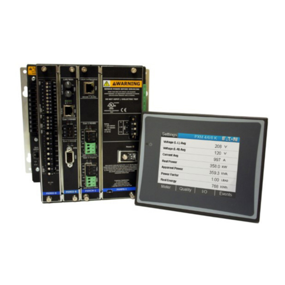
- Page 1 Effective January 2017 Instruction Booklet IB02601007E Supercedes January 2012 Power Xpert Meter 4000/6000/8000 ® Quick Start Guide www.eaton.com...
- Page 2 EATON. THE CONTENTS OF THIS DOCUMENT SHALL NOT BECOME PART OF OR MODIFY ANY CONTRACT BETWEEN THE PARTIES. In no event will Eaton be responsible to the purchaser or user in contract, in tort (including negligence), strict liability or otherwise for any special,...
-
Page 3: Table Of Contents
Table of Contents 1. Introduction ................5 1.1. Safety Precautions ..............5 2. Quick Start Guide for the Meter .......... 7 2.1. Safety Precautions ............... 7 2.2. Power Supply Connections..........8 2.3. Configure the Security Mode Dip Switches ......9 2.4. -
Page 5: Introduction
FAILURE TO GROUND THE POWER XPERT METER MAY RESULT IN INJURY, DEATH ® OR EQUIPMENT DAMAGE. Properly ground the Power Xpert Meter during installation. ® www.eaton.com IB02601007E Page 5... - Page 6 1. Introduction Page 6 IB02601007E www.eaton.com...
-
Page 7: Quick Start Guide For The Meter
The current terminal block retaining screws are part of the matching hood assembly. The current terminal block and hood assembly must be properly installed with retaining screws to secure the current terminal block to the meter housing to prevent exposure to shock hazard. www.eaton.com IB02601007E Page 7... -
Page 8: Power Supply Connections
Status LED will blink red if there are unacknowledged events. Refer to Troubleshooting Section in this manual. PXMPS-1 Card Power Supply Connection PS1-3 PS1-2 PS1-1 Power Health & Status LEDs Protective Earth Ground Figure 1: Meter Power Supply Connection and LED Locations. Page 8 IB02601007E www.eaton.com... -
Page 9: Configure The Security Mode Dip Switches
The meter will indicate that it’s in factory test mode through a repeating series of three flashes on the red Status LED DIP Switches Tamper Seals Figure 2: Meter’s Dip Switches and Tamper Seals. www.eaton.com IB02601007E Page 9... -
Page 10: Com Reset Switch
Primary settings are 120-500,000, for a PT ratio of 120:120 to 500000 to 120. It is strongly recommended that the Voltage Inputs be con- nected to the Meter by way of properly rated disconnect switches. Page 10 IB02601007E www.eaton.com... -
Page 11: Establishing Communications Between The Meter And The Displays
2.7. Establishing Communications between the Meter and the Displays 1. 6-inch color touchscreen display: See TD150015EN (available on the Eaton website, www.eaton.com/meters) for instructions on how to connect the 6-inch display to the Meter. 2. 12-inch advanced color touchscreen display: See TD150019EN (available on the Eaton website, www.eaton.com/meters) for instructions on how to connect the 12-inch display to... -
Page 12: Connecting To A Meter Using The Embedded Web Server Interface
For PXCM Cards, the local configuration port may require the use of a UTP Cat 5 cross over cable. The PXMCM card accepts a standard Cat 5 patch cable. TXRX LED Link LED Figure 4: Connect Laptop to Meter. Page 12 IB02601007E www.eaton.com... -
Page 13: Programming The Meter Via The Optional Communications Expansion Card
PXM4/6/8k CM1 “Local Configuration” web server interface. This will be required if DHCP will not be used. Power cycle the PXM4/6/8k to initiate DHCP. CE 1 CE 2 CE Card CE 3 CE 4 Figure 5: Ethernet and Modbus Connections. www.eaton.com IB02601007E Page 13... - Page 14 Log In, you will be asked to change the admin password. 3. On the Meter Webserver home page, click Settings, then Quick Setup to display basic configuration setup. 4. Click Edit to make changes to these parameters. Page 14 IB02601007E www.eaton.com...
- Page 15 The port defaults as a Master Gateway, which relays Ethernet Modbus TCP command to slave meters connected to the same RS485 link. The Modbus slave address may be set via the Display or with a web browser. www.eaton.com IB02601007E Page 15...
- Page 16 2. Quick Start Guide for the Meter Page 16 IB02601007E www.eaton.com...
-
Page 17: Mounting And Wiring
Eaton website, www.eaton.com/meters). 4. To mount the 6-inch display and the Meter back-to-back, see IL150006EN (available on the Eaton website, www.eaton.com/meters) for information on the Back to Back Meter to Display Projection Mount Adapter Kit. Note: Only the 6-inch display can be mounted back-to-back with the meter, the 12- inch display must be mounted separately. -
Page 18: Wiring
Shorting blocks for CTs and a three-phase switch or cir- cuit breaker for voltage are recommended near the equipment for ease of installa- tion. If assistance with the selection process is desired, contact Power Quality Technical Support representative. Page 18 IB02601007E www.eaton.com... - Page 19 3. Mounting and Wiring Wiring Diagrams Figure 7: 3-Phase 3-Wire Delta (Up to 480 Volts). Direct Voltage and External Current Transformers. Figure 8: 3-Phase 3-Wire Delta (Up to 480 Volts). External Voltage and External Current Transformers. www.eaton.com IB02601007E Page 19...
- Page 20 3. Mounting and Wiring Figure 9: 3-Phase 3-Wire Delta (Up to 480 Volts) 2 CTs. External Voltage and External Current Transformers. Figure 10: 3-Phase 4-Wire Y (Up to 600 Volts). Direct Voltage and External Current Transformers. Page 20 IB02601007E www.eaton.com...
-
Page 21: Fuses
24v source and communication terminals. RS485 fail safe biasing resistors are used at each master port. Eaton strongly recommends using ferrules when connecting to a terminal block. When connecting to a terminal block, the twisted pair sensitivity is critical for COM0, COM1, and COM2. -
Page 22: Rs485 Network
• Tie the communication cable shield wire to ground at one location only. • Data line definition - as per the RS485 standard - in an idle marked state (logic 1) Data B (+) will be electrically > than Data A (-). Page 22 IB02601007E www.eaton.com... - Page 23 Phoenix Contact and many other vendors carry ferrules and crimping tools for this pur- pose. For more information about RS485 wiring, please refer to TD 17513, Eaton Electrical field Devices Communication Wiring Specification. www.eaton.com...
- Page 24 3. Mounting and Wiring Page 24 IB02601007E www.eaton.com...
-
Page 25: Ratings
Voltage Rating 24 - 48 VDC • Maximum Power Rating 50 W max. • Installation Category CAT III Metering Circuits • CT Current Inputs • 5 A nominal, 20 A max. (ANSI class 20) • Installation Category CAT III www.eaton.com IB02601007E Page 25... -
Page 26: Meter And Display Cleaning Instructions
If the meter or display require cleaning the power and metering inputs should be turned off through their disconnects. The meter and display should be cleaned with a dry clean cloth only, no water or solvents should be used. Page 26 IB02601007E www.eaton.com... - Page 27 4. Ratings NOTES: www.eaton.com IB02601007E Page 27...
- Page 28 Power Xpert Meter 4000/6000/8000 Quick Start Guide Eaton Electrical Sector 1000 Eaton Boulevard Cleveland, OH 44122 United States 877-ETN-CARE (877-386-2273) Eaton.com © 2017 Eaton All Rights Reserved Printed in USA Publication No. IB02601007E / TBG001350 All trademarks are property of their January 2017 respective owners.
Need help?
Do you have a question about the Power Xpert Meter PXM4000 and is the answer not in the manual?
Questions and answers