
Related Manuals for Eaton IQ 200


Summary of Contents for Eaton IQ 200
- Page 1 TD 17558 Instructions for Installation, Operation, and Maintenance of Cutler-Hammer IQ 200 Electrical Distribution System Meter Effective 3/98...
-
Page 2: Table Of Contents
SECTION 3: INSTALLATION ..............12 INTRODUCTION ................12 PANEL PREPARATION..............12 3.2.1 Mounting the IQ 200 Modules as a Single Unit ..... 13 3.2.2 Mounting the IQ 200 Display and Base Modules Separately.. 13 WIRING..................... 16 3.3.1 Wiring System Current and Voltage........16... - Page 3 TD 17558 Page ii 3.3.2 Wiring Diagrams for Various System Configurations....16 3.3.3 INCOM™ Network Communications ........22 3.3.4 KYZ Pulse Initiator ...............22 SECTION 4: OPERATION .................25 GENERAL..................25 BUTTONS..................25 CONTRAST ..................26 DISPLAYED SIGN CONVENTIONS ...........26 USING THE OPERATOR PANEL ............27 SYSTEM DATA DISPLAY MODE ............28 4.6.1 3 Wire System and 4 Wire System........28 PHASE DATA DISPLAY MODE............28...
- Page 4 Maintenance and Care............41 REMOVAL AND REPLACEMENT ............41 5.2.1 General Safety Precautions ..........42 5.2.2 IQ 200 Display Module............42 5.2.3 IQ 200 Base Module ............42 GENERAL TROUBLESHOOTING PROCEDURES......43 TECHNICAL ASSISTANCE..............44 RETURN PROCEDURE ..............44 Effective 3/98...
- Page 5 Figure 3.3 Typical Mounting Options for Mounting the IQ 200 Base Module............14 Figure 3.4 Mounting Hole Pattern for the IQ 200 Base Module....15 Figure 3.5 3 Phase 3 Wire Configuration (Up to 600 Volts) ......17 Figure 3.6 3 Phase 3 Wire Configuration (Above 600 Volts)......17 Figure 3.7...
- Page 6 TD 17558 Page v Figure 4.10 INCOM™ Setup ............... 32 Figure 4.11 System Frequency..............32 Figure 4.12 Wiring Configuration ..............32 Figure 4.13 CT Ratio .................. 33 Figure 4.14 PT Ratio................... 33 Figure 4.15 Demand Window..............33 Figure 4.16 KYZ Setup ................33 Figure 4.17 Password Entry ................
- Page 7 TD 17558 Page vi List of Tables Table 2.1 IQ 200 Safety Specifications ............8 Table 2.2 IQ 200 Operating Specifications ..........9 Table 2.3 IQ 200 Metering Accuracy............10 Table 2.4 IQ 200 Measurement Ranges............10 Table 2.5 IQ 200 Physical Characteristics..........11 Table 2.6 IQ 200 Ordering Information............11...
-
Page 8: Section 1: Introduction
This Technical Document covers most aspects of installation, operation, and unit- level maintenance of the IQ 200. This document is a guide only for authorized and qualified personnel who select and use the IQ 200. Please refer to the specific WARNING and CAUTION in this section before proceeding. -
Page 9: Factory Correspondence
The IQ 200 Base Module communicates with the IQ 200 Display Module, providing access to view and reset system, phase, and min/max values, and providing for viewing and editing of setpoints. - Page 10 Apparent Power Factor (W, var, VA) Displacement Power Factor The IQ 200 provides the following data outputs: INCOM™ communications to provide information to the network master device • (see section 4.9.3 and 4.10.3 for details) KYZ Pulse Output proportional to the energy consumed by the system being •...
-
Page 11: Section 2: Hardware Description
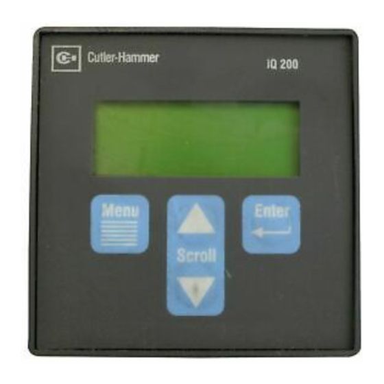
IQ 200 specifications. The IQ 200 consists of two components, the Display Module, figure 2.1, and the Base Module, figure 2.2. Do not attempt to disassemble or open the case of either the IQ 200 Display Module or the IQ 200 Base Module. The units contain no user-serviceable components. -
Page 12: Operator Panel
Change the display contrast for best viewing • The Operator Panel is an integral part of the IQ 200 Display Module. Do not attempt to remove it from the IQ 200 Display Module. 2.3 BASE MODULE REAR ACCESS AREA All wiring connections are made from the rear face of the chassis, shown in figure 2.4 below. -
Page 13: Current And Voltage Inputs
The supplied Category 5 cable connects to the DISPLAY port located on the middle right rear of the chassis and to the port on the IQ 200 Display Module. Do not route the Category 5 cable in the same enclosure or cable tray as 600V system wiring. -
Page 14: External Hardware
IQ 200 and related components from damage. 2.4.3.1 IQ 200 Power Supply External fuses should be installed in the IQ 200 power supply lines, near the IQ 200 Base Module. The fuses should be ½ Amp, 600 volt, BUSS type KTK-R-1/2 Fast Acting or equivalent. -
Page 15: Regulatory/Standards Compliance
TD 17558 Page 8 2.5.1 Regulatory/Standards Compliance The IQ 200 meets UL, CUL, and CE requirements. Table 2.1 IQ 200 Safety Specifications Safety IEC 1010-1 (1990) Incl. Amend 1&2 (1995) EN61010-1 (1993) CSA C22.2 #1010.1 (1992) UL3111 Emissions FCC Part 15 Class A... -
Page 16: Table 2.2 Iq 200 Operating Specifications
TD 17558 Page 9 Table 2.2 IQ 200 Operating Specifications Control Power Input Range 90-600 VAC±10% 48-250 VDC±10% Frequency Range 50/60 Hz — Burden 180 mA Environment Indoor use only Maximum Operating Altitude 3000 meters Operating Temperature Base Unit -20° to 50° C Display Module 0°... -
Page 17: Table 2.3 Iq 200 Metering Accuracy
TD 17558 Page 10 Table 2.3 IQ 200 Metering Accuracy Parameter Accuracy ± .5% of Full Scale Current (< 5 amps) ± .5% of Reading Current (> 5 amps) ± .5% of Full Scale Voltage, line-to-line ± .5% of Full Scale Voltage, line-to-neutral ±... -
Page 18: Ordering Information
0.06 in. front face mounting plate and 0.62 in. terminal block centered on front face mounting plate 2.6 ORDERING INFORMATION When ordering IQ 200 components, please refer to the Catalog Number listed in table 2.6. Table 2.6 IQ 200 Ordering Information... -
Page 19: Section 3: Installation
It is recommended that the IQ 200 be mounted in an electrical switchgear enclosure that is suitable for its environment. The IQ 200 Display and IQ 200 Base Modules may be mounted together or separately. The IQ 200 is designed with flexibility in mind. -
Page 20: Mounting The Iq 200 Modules As A Single Unit
Cut a ¼ DIN (92mm x 92mm) access cutout in the switchgear door or other panel where the IQ 200 is to be mounted as shown in figure 3.1. Install the IQ 200 Display Module as shown in figure 3.1, following these steps: Install the supplied gasket •... -
Page 21: Figure 3.3 Typical Mounting Options For Mounting
Display Module Cut a ¼ DIN (92mm x 92mm) access cutout in the switchgear door or other panel where the IQ 200 is to be mounted as shown in figure 3.1. Install the IQ 200 Display Module as shown in figure 3.1, followin g these steps: Install the supplied gasket when using in NEMA 12 applications. -
Page 22: Figure 3.4 Mounting Hole Pattern For The Iq 200 Base Module
Connect the IQ 200 Display Module to the IQ 200 Base Module by inserting one end of a Category 5 cable into the port on the IQ 200 Display Module, and the other end into the DISPLAY port on the IQ 200 Base Module. -
Page 23: Wiring
The IQ 200 requires conn ection to system currents and voltages. If mounted separately, the cases of IQ 200 Display Module and the IQ 200 Base Module case must be connected to earth ground. If mounted together as one unit, the case of the IQ 200 Base Module must be connected to earth ground. -
Page 24: Figure 3.5 3 Phase 3 Wire Configuration (Up To 600 Volts)
TD 17558 Page 17 3 Phase 3 Wire (Up to 600Volts) LINE LOAD IQ 200 VA VB VC NEU PS1 PS2 Case Ground FUSE (90-600VAC) Control Power (48-250VDC) Figure 3.5 3 Phase 3 Wire Configuration (Up to 600 Volts) 3 Phase 3 Wire (Above 600Volts) -
Page 25: Figure 3.7 3 Phase 3 Wire, 2 Ct Configuration (Up To 600 Volts)
Page 18 3 Phase 3 Wire (Up to 600Volts) using only 2CTs, Line 2 will be in error by the amount of ground current. LINE LOAD IQ 200 VA VB VC NEU PS1 PS2 Case Ground FUSE (90-600VAC) Control Power (48-250VDC) Figure 3.7 3 Phase 3 Wire, 2 CT Configuration (Up to 600 Volts) -
Page 26: Figure: 3.9 3 Phase 4 Wire Configuration (Up To 600 Volts)
TD 17558 Page 19 3 Phase 4 Wire (Up to 600Volts) LINE LOAD IQ 200 VA VB VC NEU PS1 PS2 Case Ground FUSE (90-600VAC) Control Power (48-250VDC) Figure: 3.9 3 Phase 4 Wire Configuration (Up to 600 Volts) 3 Phase 4 Wire (Above 600Volts) -
Page 27: Figure 3.11 3 Phase 3 Wire Configuration (Above 600 Volts) Line Powered
Page 20 3 Phase 3 Wire (Above 600Volts) (line powered) LINE LOAD FUSE Open Delta Connection IQ 200 VA VB VC NEU PS1 PS2 Case Ground FUSE (90-600VAC) Control Power (48-250VDC) Figure 3.11 3 Phase 3 Wire Configuration (Above 600 Volts) Line Powered... -
Page 28: Figure 3.13 Single Phase 3 Wire Configuration (Up To 600 Volts)
TD 17558 Page 21 Single Phase 3 Wire (Up to 600Volts) LINE LOAD IQ 200 VA VB VC NEU PS1 PS2 Case Ground FUSE (90-600VAC) Control Power (48-250VDC) Figure 3.13 Single Phase 3 Wire Configuration (Up to 600 Volts) Single Phase 2 Wire (Up to 600Volts) -
Page 29: Incom™ Network Communications
RULES for more detailed information. Connect the IQ200 to the IMPACC network by connecting the twisted pair communication cable to the INCOM™ port located on the rear face of the IQ 200 Base Module. The polarity of the twisted pair is not important. - Page 30 PT = 2:1 Desired value to monitor Watt-hours System parameters Assume the IQ 200 is monitoring a constant system power of 16,800 Watts. Step 1: Calculate the CT and PT ratios CT ratio = 1400/5 = 280 PT ratio = 2/1=2...
-
Page 31: Figure 3.16 2-Terminal (K-Y) Configuration
TD 17558 Page 24 ∆ T ∆ T Figure 3.16 2-Terminal (K-Y) Figure 3.17 3-Terminal (K-Y-Z) Configuration Configuration Effective 3/98... -
Page 32: Section 4: Operation
IQ 200 should it be networked to an IMPACC master device. All functions of the IQ 200 are available through menus visible on the screen of the IQ 200 Display Module Operator Panel. Choice of menu and selection of menu options is accomplished by pressing the buttons on the face of the Operator Panel. -
Page 33: Contrast
Enter button while pressing the Scroll up arrow button (to decrease contrast) or the Scroll down arrow button (to increase contrast). 4.4 DISPLAYED SIGN CONVENTIONS The IQ 200 not only displays system values, but also indicates whether factors are lagging or leading by displaying the following symbols: Display... -
Page 34: Using The Operator Panel
Figure 4.1 System Power Values Relationships 4.5 USING THE OPERATOR PANEL When the IQ 200 is first powered on, the Operator Panel screen displays a brief initialization message identifying the product and version. The screen then displays the System Power screen. (At this point, pressing the Scroll arrows will display system data as described in section 4.6 System Data Display Mode.) -
Page 35: System Data Display Mode
4.6 SYSTEM DATA DISPLAY MODE The System Data menu provides access to System information monitored by the IQ 200. Press Menu to display the list of available items. Position the selection arrow next to the System Data menu item and press Enter. -
Page 36: Wire System
The 10 screens shown in figure 4.5 display as the Scroll down arrow is pressed. Figure 4.5 Phase Display 4 Wire Systems 4.8 MIN/MAX DATA DISPLAY MODE 4.8.1 3 Wire System These screens, shown in figure 4.6, display the minimums and maximums of values monitored by the IQ 200. Effective 3/98... -
Page 37: Wire System
4.8.2 4 Wire System These screens, shown in figure 4.7, display the minimums and maximums of values monitored by the IQ 200. Press Menu to display the list of available items. Position the selection arrow next to Min/Max Data and press Enter. -
Page 38: View Setpoints (3 And 4 Wire Systems)
Figure 4.7 Min/Max Data Display, 4 Wire System 4.9 VIEW SETPOINTS (3 and 4 wire systems) This menu selection permits the user to view but not change all of the IQ 200 setpoints and system parameters. To change these values, proceed to section 4.10 Edit Setpoints. -
Page 39: Incom™ Setup
Page 32 One screen, figure 4.7, indicates that no password is necessary to change the IQ 200 setpoints or system parameters. The other screen, figure 4.8, indicates that a password is required to change setpoints or system parameters. Figure 4.8 No Password Required Figure 4.9 Password Required... -
Page 40: Ct Ratio
This screen, shown in figure 4.13, indicates the current transformer ratio selected as the ratio of the current transformers being used with the IQ 200. If the ratio displayed is not correct, proceed to section 4.10 Edit Figure 4.13 CT Ratio Setpoints. -
Page 41: Edit Setpoints (3 And 4 Wire Systems)
TD 17558 Page 34 4.10 EDIT SETPOINTS (3 and 4 wire systems) This menu selection permits the user to change all of the IQ 200 setpoints and system parameters. Press Menu to display the list of available items. Position the selection arrow next to Edit Setpoints and press Enter. -
Page 42: Incom™ Setup
Position the selection arrow next to INCOM™ Setup and press Enter. This screen, shown in figure 4.19, displays the baud rate at which the IQ 200 will communicate over the INCOM ™ network, and indicates the network address (in hexadecimal) currently assigned to the IQ 200. -
Page 43: System Frequency
Position the selection arrow next to CT Ratio and press Enter. This screen, shown in figure 4.22, displays the ratios of the current transformers connected to the IQ 200. This screen initializes with the ratio of the current transformers being used with the IQ 200 selected and displayed. -
Page 44: Pt Ratio
TD 17558 Page 37 used with the IQ 200, press either of the Scroll arrows repeatedly to step through the choices individually, or press and hold either of the Scroll arrows to step through the choices rapidly. There are 256 choices from 5 to 8000, displayed as follows: 5 to 110 in increments of 5 •... -
Page 45: Demand Window
The Demand Window is a fixed period of time over which average system parameters are calculated. For example, setting the Demand Window to 15 instructs the IQ 200 to calculate the average current or power over the past 15 minutes and to update that calculation every 15 minutes. -
Page 46: Exit
Menu. 4.11 RESET VALUES This menu item allows the user to reset to zero or to default IQ 200 system values and parameters. Press Menu to display the list of available items. Position the selection arrow next to Reset Values and press Enter. -
Page 47: Contrast Adjust
TD 17558 Page 40 Pressing Enter while No is selected returns to the Reset Values screen. To change the selection to Yes, press either of the Scroll arrows to toggle between No and Yes. When Yes is displayed as selected, press Enter to lock in the selection. If the procedure completes successfully, Download Accepted appears briefly. -
Page 48: Section 5: Troubleshooting And Maintenance
Never clean the IQ 200 with system or IQ 200 power on. Clean the IQ 200 using only a clean, dry cloth. Do not use water or solvents of any kind. -
Page 49: General Safety Precautions
Disconnect the Category 5 cable from the IQ 200 Display Module, and mark it for • later reconnecting. If the IQ 200 Base Module is attached to the IQ 200 Display Module, remove it by • disengaging its DIN clip from the DIN rail mounted on the IQ 200 Display Module. -
Page 50: General Troubleshooting Procedures
Page 43 5.3 GENERAL TROUBLESHOOTING PROCEDURES These procedures cover the IQ 200 only, and can only indicate or eliminate the IQ 200 as a cause of the malfunction. Because these procedures are not exhaustive, the user must be aware that other system components may be causing or contributing to system malfunctions. -
Page 51: Technical Assistance
IQ 200 or by other external circumstances. If the malfunction is determined to be within the IQ 200, return the IQ 200 to Cutler- Hammer for repair or replacement. To return the IQ 200, contact the local authorized Cutler-Hammer distributor for specific instructions. - Page 52 TD 17558 Effective 3/98...
- Page 53 TD 17558 Effective 3/98...
- Page 54 TD 17558 Effective 3/98...
- Page 55 TD 17558 Five Parkway Center Pittsburgh, PA 15220 Effective 3/98 Stlye 8163A33H01 Printed in U.S.A.
Need help?
Do you have a question about the IQ 200 and is the answer not in the manual?
Questions and answers