Siemens SITRANS FUP1010 Operating Instructions Manual
Ultrasonic flowmeters
7me3510 portable flowmeter
Hide thumbs
Also See for SITRANS FUP1010:
- Operating instructions manual (214 pages) ,
- Quick start (2 pages) ,
- Quick start manual (46 pages)

Related Manuals for Siemens SITRANS FUP1010


Summary of Contents for Siemens SITRANS FUP1010
- Page 1 Ultrasonic flowmeters SITRANS FUP1010 IP67 7ME3510 Portable Flowmeter Operating Instructions - February 2010 SITRANS F...
- Page 3 Introduction Safety notes Description SITRANS F Installing/mounting Ultrasonic Flowmeter FUP1010 IP67 Portable Flowmeter Connecting Commissioning Operating Instructions Functions Alarm, error, and system messages Maintenance and service Troubleshooting Technical data Appendix Appendix 02/2010 A5E02951522A Revision 01...
- Page 4 Note the following: WARNING Siemens products may only be used for the applications described in the catalog and in the relevant technical documentation. If products and components from other manufacturers are used, these must be recommended or approved by Siemens. Proper transport, storage, installation, assembly, commissioning, operation and maintenance are required to ensure that the products operate safely and without any problems.
-
Page 5: Table Of Contents
Table of contents Introduction..............................7 Preface............................7 Items supplied..........................7 History............................7 Further Information........................8 Safety notes..............................9 Laws and directives........................9 Lithium batteries..........................10 Description..............................11 FUP1010 features........................11 Applications..........................12 Theory of Operation........................13 Installing/mounting............................19 Installation safety precautions.....................19 Use according to specifications....................19 Application Guidelines.........................20 Charging the Battery........................20 Connecting..............................23 Transmitter Wiring........................23 5.1.1 Connecting Battery Power......................23 5.1.2... - Page 6 Table of contents Functions..............................73 Selecting Flow Units........................73 Span Data............................76 Logger Control..........................78 Operation Adjust Menu Settings....................81 Setting Relays..........................84 Memory Control...........................86 Analog Output Setup........................87 Analog Input Setup........................89 Analog Output Trim........................91 7.10 RTD Calibration...........................94 7.11 Reflexor............................96 Alarm, error, and system messages......................109 Alarm Letter Codes and Descriptions..................109 Maintenance and service..........................111 Maintenance..........................111 Replacing the battery.........................111...
- Page 7 Table of contents Glossary..............................151 Index.................................157 Tables Table 4-1 Power Cord Codes........................21 Table 5-1 Pipe Configuration Option List Definitions...................36 Table 6-1 Key Pad Function Chart......................67 Table 7-1 Totalizer Modes...........................74 Table 7-2 Totalizer Controls (the "n" in <Fn> = channel number)*..............75 Table 7-3 Logger Control Menu Option List....................78 Table 7-4 Relay Option List.........................84...
- Page 8 Table of contents Figure 5-7 Pipe Surface Preparation......................32 Figure 5-8 Reflect Mount with EZ-Clamp and Spacer Bar................38 Figure 5-9 Sensor Mounting with E-Z Clamp and Spacer Bar..............39 Figure 5-10 E-Z Clamp S-Hook........................39 Figure 5-11 Sensor............................40 Figure 5-12 Connecting Sensors to Flowmeter....................41 Figure 5-13 Mylar Spacing Guide........................42 Figure 5-14...
-
Page 9: Introduction
Introduction Preface These instructions contain all the information you need for using the device. The instructions are aimed at persons mechanically installing the device, connecting it electronically, configuring the parameters and commissioning it as well as service and maintenance engineers. Note It is the responsibility of the customer that the instructions and directions provided in the manual are read, understood and followed by the relevant personnel before installing the... -
Page 10: Further Information
Product information on the Internet The Operating Instructions are available on the CD-ROM shipped with the device, and on the Internet on the Siemens homepage, where further information on the range of SITRANS F flowmeters may also be found: Product information on the internet (http://www.siemens.com/flow) -
Page 11: Safety Notes
Material compatibility Siemens Flow Instruments can provide assistance with the selection of sensor parts. However, the full responsibility for the selection rests with the customer and Siemens Flow Instruments can take no responsibility for any failure due to material incompatibility. -
Page 12: Lithium Batteries
Safety notes 2.2 Lithium batteries ● Pressure equipment Directive (PED) 97/23/EC ● ATEX Directive 94/9/EC Lithium batteries Lithium batteries are primary power sources with high energy content designed to represent the highest possible degree of safety. WARNING Potential hazard Lithium batteries may present a potential hazard if they are abused electrically or mechanically. -
Page 13: Description
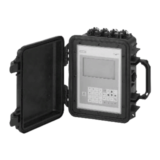
Description FUP1010 features Description The Siemens SITRANS FUP1010 Weatherproof IP67 Portable flowmeters achieve highly accurate flow measurements using ultrasonic transit-time technology. The sensors are mounted on the outside of the pipe, preventing contact with the medium. This means no cavities or clogging by high paraffin liquids found in many hydrocarbon applications. -
Page 14: Applications
Description 3.2 Applications Channel Functions The system software allows simultaneous operation of one channel in the Transit-Time mode and the other in Reflexor mode. Transit-Time Mode All SITRANS F 1010 models use transit-time flow measurement technology varying only in functionality and environmental housing. Reflexor Mode The SITRANS F 1010 transit-time flowmeter is highly resistent to the effects of liquid non- homogeneity caused by the inclusion of air or solid particulate. -
Page 15: Theory Of Operation
Description 3.3 Theory of Operation ● Chemical Processing ● Food and Pharmaceutical ● Aircraft Avionics and Ground Support ● Water and Wastewater ● Aerospace ● Automobile Manufacturing ● Hydrocarbon Industries Theory of Operation The liquid flowmeter relies on the MultiPulse transit. Two Wide-Beam ultrasonic sensors per measuring path, alternating as transmitter and receiver, are used to interrogate the liquid flowing within the metering section. - Page 16 Description 3.3 Theory of Operation ∅° = sin (VOS / V Where: VOS = Velocity of sound in liquid phase = Phase velocity of sensor phase = 2 * ID / (VOS * cos ∅) ID = Pipe inside diameter = Transit time in liquid * DT / (2 * TL) DT = Measured Transit-Time difference...
- Page 17 Description 3.3 Theory of Operation Volume Correction Algorithm The flowmeter provides Standard Volume output by inferentially determining the liquid API @ F (or the specified base temperature) and then applying the API standard (2540) algorithm as outlined below. Before describing API algorithm the steps required to obtain bulk or actual flow should be reviewed.
- Page 18 Description 3.3 Theory of Operation 2-Channel Dual Channel provides two independent measurement channels that operate simultaneously. Depending on the specific model, Dual Channel supports: Clamp-on Transit-time, In-line Transit-time and Reflexor. ① ⑤ Upstream Sensors Pipe B Output Flow ② ⑥ Downstream Sensors Channel 2 for Pipe B ③...
- Page 19 Description 3.3 Theory of Operation Wide Beam Transmission As shown in the figure below, an ultrasonic sensor induces an axial sonic beam within the wall of the pipe. These vibrations spread along the pipe wall and then enter the liquid in the form of a Wide Beam wave front traveling at an angle to the main pipe axis.
- Page 20 Description 3.3 Theory of Operation Reflect mounting automatically corrects for non-axial flow or cross flow conditions. When the exchange of sonic signals occurs by reflection off the far pipe wall as shown above, the average beam versus stream angle will be equivalent to that of an axial flow stream. FUP1010 IP67 Portable Flowmeter Operating Instructions, 02/2010, A5E02951522A Revision 01...
-
Page 21: Installing/Mounting
Installing/mounting Installation safety precautions WARNING In applications with working pressures/media that can be dangerous to people, surroundings, equipment or others in case of pipe fracture, we recommend that special precautions such as special placement, shielding or installation of a security guard or a security valve are taken when the sensor is mounted. -
Page 22: Application Guidelines
● Use the flowmeter as support of external loads like pipes, etc. ● Change the flowmeter in any way. For e.g. decomposition of material in connection with processing, welding and use of accessories and spare parts not approved by Siemens Flow Instruments. -
Page 23: Table 4-1 Power Cord Codes
Installing/mounting 4.4 Charging the Battery ① IEC 320 Power Inlet ② Connector ③ 0,9 meters minimum (3 ft) ④ NEMA 5 - 15P (see Power Cord table) ⑤ IEC 320 Plug (see Power Cord table) Figure 4-1 Power Adapter/Battery Charger Table 4-1 Power Cord Codes Assembly P/N... - Page 24 Installing/mounting 4.4 Charging the Battery 1015BCK-1 NEM 5-15P 10A / 120VAC 1015BCL-1 SEV 1011 10A / 250VAC FUP1010 IP67 Portable Flowmeter Operating Instructions, 02/2010, A5E02951522A Revision 01...
-
Page 25: Connecting
Connecting Transmitter Wiring 5.1.1 Connecting Battery Power Battery Operation All portable systems include battery chargers that operate from an AC voltage source. We strongly recommend that you "form" and charge the battery before operating the system for the first time. The Charge Indicator LED A battery status indicator shows the status of its internal battery and charging circuits. - Page 26 Lead/Acid battery design that features a deep discharge cycle for extended operation. CAUTION Do not use any other external Battery Charger/Pack combination with the flowmeter unless reviewed and pre-approved by Siemens. CAUTION Do not leave the Battery Charger connected to the Battery Pack during transportation or storage.
-
Page 27: Figure 5-1 External Battery Pack
Connecting 5.1 Transmitter Wiring ① Battery Lead Acid Gel (12VDC, 3 AH) ② Female "Cigarette" Connector ③ Adapter Cable 1.22 meters Extended (4 ft) Figure 5-1 External Battery Pack Charging the External Battery Pack FUP1010 IP67 Portable Flowmeter Operating Instructions, 02/2010, A5E02951522A Revision 01... - Page 28 Connecting 5.1 Transmitter Wiring DANGER Attempting to use the unit in a submerged environment with the cover open or latches not engaged will result in damage to the unit that cannot be repaired and could expose the user to the risk of electric shock. CAUTION Charge the 1015BB Battery Pack (7ME39403BB00) in a completely dry environment only.
-
Page 29: Figure 5-2 1015Bck-2 And 1015Bca-2 Battery Chargers
Connecting 5.1 Transmitter Wiring ① Plug Type CEE 7/16 (EUR) ② Plug Type NEMA 1-15P (USA) ③ Cord 1829 mm (6 ft) ④ Male "Cigarette" Connector Figure 5-2 1015BCK-2 and 1015BCA-2 Battery Chargers Note A [LOBAT] flag appears on the flowmeter graphic screen when the remaining battery operating time is less than 20 minutes. -
Page 30: Connecting Ac Power
Connecting 5.2 Sensor Wiring Status Indication Action Battery Warning Beeper Normal operation, periodic audible alarm Connect a Battery Charger for continued operation. Battery Discharge Unit will not turn on (no display screen) Connect to Battery Charger for at least 1.5 hours before attempting to operate. 5.1.2 Connecting AC Power Using the 1015BCK-1 (7ME39404PG00) Power Adapter/Charger... -
Page 31: Figure 5-4 Reflect Mount (Pipe Shown From Above In 12 O'clock Position)
Connecting 5.2 Sensor Wiring Note When installing sensors, do not key in the V/M (Version/Modification) label number as the Sensor Size. Clamp-on Sensor Mounting Modes The transmitter recommends a mounting mode after analyzing your pipe and liquid data entries. However, you can install clamp-on sensors in the way that best suits your application and the sensor type you have purchased. -
Page 32: Figure 5-5 Direct Mount (Pipe Shown From Above In 12 O'clock Position)
5. Do not mount sensors from different ultrasonic flow meters on the same pipe. Also, do not run the sensor cables in common bundles with cables from communication equipment, other Siemens systems, or any type of ultrasonic equipment. You can run these cables through a common conduit ONLY if they originate at the same flowmeter. -
Page 33: Figure 5-6 Sensor Alignment (Horizontal Plane)
Connecting 5.2 Sensor Wiring 6. Never mount sensors under water, unless you order submersible units and you install them in accordance with factory instructions. 7. Never mount sensors on the top or bottom of a horizontal pipe. The best placement on a horizontal pipe is either the ten o’clock and two o’clock position for Reflect Mode, or one sensor at nine o’clock and one sensor at three o’clock for Direct Mode. -
Page 34: Sensor Identification And Selection
Connecting 5.2 Sensor Wiring 3. After receiving the spacing dimensions from the Installation Menu, prepare the pipe surface. De-grease the surface, if necessary, and remove any grit, corrosion, rust, loose paint, etc. Use abrasive material provided to provide a clean contact surface for the sensors. Note Please note that the instructions show vertical mounting for clarity purposes only. -
Page 35: Setting The Parameters
Connecting 5.2 Sensor Wiring 1011 Universal series sensors and mounting frames have the following color codes for easy identification: ● Gold - size 'A' ● Blue - size 'B' ● Red - size 'C' ● Green - size 'D' ● Black - size 'E' Note Check to make sure that the sensors are a matched set with the same serial numbers and marked with an "A"... - Page 36 Connecting 5.2 Sensor Wiring Select a Meter Type 1. Press the <MENU> key and select the Meter Type. 2. Press the <Right Arrow> and scroll to [Dual Path Flow]. 3. Press <ENT> to select. The [Dual Path Flow] menu will appear. 4.
- Page 37 Connecting 5.2 Sensor Wiring 4. Scroll to [Save/Rename Site]. Press <Right Arrow> then press <ENT> to save site. 5. Press <Left Arrow> and return to the main menu. Select Pipe Class 1. Press the <Down Arrow> and then <Right Arrow> to highlight [Pipe Data]. 2.
-
Page 38: Table 5-1 Pipe Configuration Option List Definitions
Connecting 5.2 Sensor Wiring Select Pipe Configuration 1. Scroll down to [Pipe Config] and press the <Right Arrow>. 2. Select a configuration that approximates the conditions upstream of your sensor mounting location. (Refer to the definitions below.) 3. Press <ENT> to save selection. ①... -
Page 39: Reflect Mount
Connecting 5.2 Sensor Wiring Sensor Selection The following is a typical sensor installation procedure for D1H High Precision sensors. 1. Press <Left Arrow> to return to Main Menu. At the Main Menu, press the <Down Arrow> to select [Pick/Install Xdcr]. 2. - Page 40 Connecting 5.2 Sensor Wiring ① ⑤ Sensor cable connection Customer's Pipe ② ⑥ 1011HPS Series Sensor Sensor Index Screw ③ ⑦ Spring Clip Sensor Index Screws-Storage Location ④ ⑧ Spacer Bar 1011PPS Series Sensor Figure 5-8 Reflect Mount with EZ-Clamp and Spacer Bar Installation Procedure 1.
-
Page 41: Figure 5-9 Sensor Mounting With E-Z Clamp And Spacer Bar
Connecting 5.2 Sensor Wiring 4. One sensor is attached using the "REF" hole on the spacer bar. The second sensor is attached to the spacer bar at the index hole specified by the Number Index recorded in Step 1. Note In some cases, the sensors may have two sets of securing holes. -
Page 42: Figure 5-11 Sensor
Connecting 5.2 Sensor Wiring 9. Take sensor and apply a continuous lengthwise 3 mm (1/8-inch) bead of coupling compound across the center of the sensor emitting surface. ① ④ Cable Connector Front Edge ② ⑤ Angled Edge Emitting Surface ③ ⑥... -
Page 43: Direct Mount
Connecting 5.2 Sensor Wiring 15.Observing the upstream and downstream orientation, attach the UP and DN cables to the sensors and make snug. Attach the other ends to the UP and DN terminals of the flowmeter (see figure below). ① ③ CH 1 Flow Sensor Cable Connectors Channel 1 - Downstream Sensor ②... - Page 44 Connecting 5.2 Sensor Wiring Figure 5-13 Mylar Spacing Guide Installation Procedure 1. Make a note of the Number Index displayed in the [Install Xdcr] menu. Check to ensure that you have a matched set of sensors. They both should have the same S/N number but marked with either an "A"...
-
Page 45: Figure 5-14 Ez Clamping Sensor To Pipe
Connecting 5.2 Sensor Wiring ① ④ Adjusting Nut E-Z Clamp Chain ② ⑤ Bit Snap Pipe ③ Sensor Figure 5-14 EZ Clamping Sensor to Pipe Note To surround larger pipes, link multiple lengths of chain together by mating the Bit Snap and "S"... - Page 46 Connecting 5.2 Sensor Wiring 7. While holding this sensor in place, bring the chain around the pipe and attach the closest cross-link onto the "S" hook of the EZ clamp. 8. Tighten the adjusting nut until the chain is just snug around the pipe. Ensure that the chain is straight around the pipe and the sensor contacts the pipe at the white dot just under the front label.
- Page 47 Connecting 5.2 Sensor Wiring 15.Use the spacer bar as a straight edge, align the mounted sensor's white dot and the pencil dot and draw a line across the dots (see "B" below). Set spacer bar aside. ① ⑤ Sensor 1 Sensor Edge Line ②...
-
Page 48: Figure 5-17 Wrapping The Mylar Spacing Guide Around The Pipe (End View)
Connecting 5.2 Sensor Wiring 16.Wrap the Mylar spacing guide around the pipe so that the left edge is against the sensor edge mark (see "C" above). Arrange so that one end overlaps the other by at least 8 cm (3 inches). Trim to fit if necessary, but in order to keep the end square, be sure not to trim at the overlapping end. -
Page 49: Figure 5-19 Aligning The Sensors For Direct Mode (End View)
Connecting 5.2 Sensor Wiring 20.Temporarily position the sensor (in the 3 o’clock position opposite the mounted sensor - see below) where it will be mounted. Ensure that this is a smooth area without any raised spots (seams, etc.). With a pencil or chalk, mark a generous area around all sides of the mounting frames. -
Page 50: 1012T Mounting Tracks
Connecting 5.2 Sensor Wiring 28.Observing the upstream and downstream orientation, attach the UP and DN cables to the sensors and make snug. Attach the other ends to the UP and DN terminals of the flowmeter (see figure below). ① ③ CH 1 Flow Sensor Cable Connectors Channel 1 - Downstream Sensor ②... - Page 51 Connecting 5.2 Sensor Wiring [Install Xdcr] menu screen. Note the automatic assignment of mounting track part numbers, plus the designation of the Number Index. ① Sensor type, size and mounting mode selection. ② Automatic selection of mounting track part number and Number Index. FUP1010 IP67 Portable Flowmeter Operating Instructions, 02/2010, A5E02951522A Revision 01...
-
Page 52: Figure 5-21 Reflect Mount With Model 1012Tp Mounting Track (Side View)
Connecting 5.2 Sensor Wiring 1. Perform all required menu steps up until the point where you respond to the [Install Complete?] prompt. 2. Make a note of the Number Index displayed in the [Install Xdcr] menu. Check to ensure that you have a matched set of sensors. They both should have the same S/N number but marked with either an "A"... -
Page 53: Figure 5-22 Reflect Mode Chain Loop (Front View)
Connecting 5.2 Sensor Wiring 4. Holding the track assembly in place, loop one of the roller chains under the pipe, pull it around and maintain tension while slipping a link over the tension screw hook. Tighten the tension screw enough to hold the assembly on the pipe, but still allow rotation. Repeat for the other roller chain. - Page 54 Connecting 5.2 Sensor Wiring [Install Xdcr] menu screen. Note the automatic assignment of model numbers for the sensor and mounting track, plus the designation of the Number Index. ① Automatic selection of mounting track part number , mount mode and Number Index The combination of two Model 1012TP Mounting Tracks and a spacer guide is the recommended way to mount sensors in the Direct Mode.
- Page 55 Connecting 5.2 Sensor Wiring ● Reflect Mode Track Assembly - This track rail includes the Tension Screw and REF hole to position one sensor. ● Direct Mode Track Assembly - This track rail has number index holes for inserting an index pin to position the other sensor.
-
Page 56: Figure 5-23 Direct Mount 180° Opposed With Mounting Tracks
Connecting 5.2 Sensor Wiring ① ⑧ Tension Screw Pipe ② ⑨ To SITRANS F 1010 Flowmeter 1011PPS Series Sensor Downstream ③ ⑩ 1012C Series Cable Number Index pin hole ④ ⑪ Right Angle BNC Adapter Flow direction ⑤ ⑫ Sensor Clamp 1012TP Series Mounting Track (D) ⑥... - Page 57 Connecting 5.2 Sensor Wiring Track Assembly Installation 1. Perform all required menu programming steps up until the point where you respond to the [Install Complete?] prompt. 2. Make a note of the Number Index displayed in the [Install Xdcr] menu. Check to ensure that you have a matched set of sensors.
-
Page 58: Figure 5-24 Direct Mount Roller Chain
Connecting 5.2 Sensor Wiring 5. Wrap the chain around the pipe; first onto the centering pin on the bottom track and then onto the hook on the top track. ① ⑤ Chain Tension Screw Centering Pin ② ⑥ Chain Hook Sensor 1 and Clamping Screw ③... -
Page 59: Figure 5-25 Wrapping The Mylar Spacing Guide Around Pipe (End View)
Connecting 5.2 Sensor Wiring Positioning Track Assemblies 1. Wrap a length of the Mylar spacing guide around the pipe and against the end of the track assemblies. Ensure that the spacer guide edges on both sides align. Arrange so that one end overlaps the other by at least 8 cm (3 inches). -
Page 60: Figure 5-27 Track Rail Alignment
Connecting 5.2 Sensor Wiring 3. Use the edge of the Spacer Guide as a stop for both tracks to keep them parallel. Adjust tracks as necessary. ① Align tracks with Spacer Guide edge ② Mylar Spacer Guide ③ Halfway distance of Spacer Guide Figure 5-27 Track Rail Alignment 4. -
Page 61: Figure 5-28 Ref And Number Index Pin Locations
Connecting 5.2 Sensor Wiring Sensor Installation 1. Insert an index pin into the REF hole of the track marked "Reflect Mode Spacing." 2. Take one of the sensors and insert it between the track rails and to the left of the index pin with the cable connector pointing away from the pin. -
Page 62: Zero Flow Adjust Menu
(or zero offset) may be present in any installation. To eliminate this residual zero offset Siemens has developed several different methods to insure proper zero flow compensation. The following paragraphs describe each method and when they should be used. - Page 63 Connecting 5.3 Zero Flow Adjust Menu ReversaMatic This routine involves swapping the Up and Down transducers on the pipe (while keeping the cables attached) such that the difference in the transit-time change represents the zero offset. The fixed zero offset value is stored in memory in the same manner as described in Actual Zero.
- Page 64 Connecting 5.3 Zero Flow Adjust Menu When you send the command, the flowmeter analyzes the current flow rate for up to sixty seconds, integrating (averaging) the data for the best zero correlation. During this time, the menu prompt at the top of the display screen shows a timer that counts from zero to sixty. You can allow zero averaging for the entire period, or cancel the process at any time by pressing the <ENT>...
- Page 65 Connecting 5.3 Zero Flow Adjust Menu ZeroMatic (optional function) Note ZeroMatic is used in the Reflect Mode only. Invoking ZeroMatic clears any existing fixed zero offset. Use this menu cell to select the ZeroMatic option. If conditions permit the use of the Auto Zero function then the ZeroMatic option can be used as well.
-
Page 67: Commissioning
Power Adapter / Battery Charger. 1. Apply power. 2. Within 10 seconds of power-up the main display will become active and a typical Siemens graphic will appear briefly. The screen also identifies the software version of the unit as shown below. -
Page 68: Navigating The Menu
Commissioning 6.3 Navigating the Menu Final Setup 1. Press <MENU> key once to display the main menu. 2. Press <Right Arrow> twice. 3. Scroll down to [Install Complete]. Press the <Right Arrow> and select [Install]. Press <ENT>. The flowmeter will go through drives. 4. -
Page 69: Table 6-1 Key Pad Function Chart
Commissioning 6.3 Navigating the Menu Level A Level B Level C Recall Site Setup Pump 1 Pump 2 Channel Enable Create/name Site Site Security Delete Site Setup Save/Rename Site Figure 6-1 Key Pad Note Use <Left Arrow> key to return to previous menus. Table 6-1 Key Pad Function Chart Keys... -
Page 70: Installation Menus
Commissioning 6.4 Installation Menus ① ⑤ Menu Cell Data (left-hand column) Current Selected Measurement Channel ② ⑥ Highlighted Menu Cell Site Name Identified ③ ⑦ Menu Prompt Line (Reverse Video) Highlighted Data ④ ⑧ Current Selected Meter Type Menu Cell Data (right-hand column) Figure 6-2 Typical Installation Menu Screen Example Installation Menus... - Page 71 Commissioning 6.4 Installation Menus Level A Level B Level C Level D Level E Level F Level G Level H Full Site Channel Recall Site Enter From List Setup Setup Channel Enable Enter From List Create/Name Site Enter From List Site Security On/Off Delete Site...
- Page 72 Commissioning 6.4 Installation Menus Level A Level B Level C Level D Level E Level F Level G Level H Flow/Total Flow Vol. Units Enter From List Units Flow Time Units Enter From List Flow Disp. Range Enter From List Flow Disp.
- Page 73 Commissioning 6.4 Installation Menus Level A Level B Level C Level D Level E Level F Level G Level H Transducer Enter Type From List Logger Display Logger Enter Control From List Output Logger Yes/No Circular Yes/No Memory Est LogTime View Left Only...
- Page 74 Commissioning 6.4 Installation Menus Level A Level B Level C Level D Level E Level F Level G Level H RTS Key Time Enter From List Backlight Enter From List System Version View Info Only Battery View Capacity Only Reset Data/ View mm.dd.yy.hh.
-
Page 75: Functions
Functions Selecting Flow Units The [Flow/Total Units] menu is available after selecting a meter type and measurement channel. Use the [Flow/Total Units] menu to select volumetric flow units and an associated time base for the flow rate and total outputs. After making your selections, a view-only menu cell shows the resultant scaling. -
Page 76: Table 7-1 Totalizer Modes
Functions 7.1 Selecting Flow Units 5. Press the <Right Arrow> to select the option list and use the <Up/Down Arrows> to select the desired units. 6. Press <ENT> to store selection. Totalizer Modes The Totalizer function operates in any of the modes listed below: Table 7-1 Totalizer Modes Mode... -
Page 77: Table 7-2 Totalizer Controls (The "N" In
Functions 7.1 Selecting Flow Units 4. Scroll down to the [Totalizer Mode] menu and press the <Right Arrow> to select the Totalizer Mode option list. 5. Press the <Up/Down Arrows> to select the desired mode. 6. Press <ENT> to store selection. Totalizer Mode Controls Table 7-2 Totalizer Controls (the "n"...= Channel Number) -
Page 78: Span Data
Functions 7.2 Span Data CLEAR Clears the Batch/Sample Totalizer register. The flowmeter maintains a separate Totalizer register for Batching or Sampling applications but cannot be accessed (Batch/Tot register) directly. It is used for relay control only. If you assign the system relay to this function, a momentary (200 mS) relay pulse occurs whenever the BATCHTOT register accumulates a specified liquid quantity. - Page 79 Functions 7.2 Span Data Maximum span values represent: Minimum span values repressent: 100% of span 0% of span Current output of 20 mA Current output of 4 mA Voltage output of 10 Vdc Voltage output of 0 Vdc Pulse output of 5000 Hz Pulse output of 0 Hz To change the default Span Data settings: 1.
-
Page 80: Logger Control
Functions 7.3 Logger Control Logger Control Logger Control Menu The Logger Control menu in the [Meter Facilities] menu provides the Logger controls for the flowmeter measurement channels and paths. It allows the user to select data items/alarm events, a logging interval and a destination for Logger reports. While the Logger Setup menu is measurement channel/path specific, this Logger Control menu provides global control functions. - Page 81 Functions 7.3 Logger Control Display Logger This menu cell allows you to send the Logger contents to the display screen. This command is effective only after a successful install. You can set the report to scroll on the screen with or without line-wrap.
- Page 82 Functions 7.3 Logger Control 4. To transmit Logger contents to external device via the serial port press <ENT>. 5. To stop printout press <Left Arrow>. Circular Memory In its default mode, the Logger collects data until its memory becomes full. At that time the flowmeter suspends datalogging and cannot resume until the Logger memory is cleared (see Clear Logger command).
-
Page 83: Operation Adjust Menu Settings
Functions 7.4 Operation Adjust Menu Settings Clearing Logger Memory 1. To access the [Clear Logger] option list press <Right Arrow>. 2. Move the cursor to [Yes] by pressing <Up/Down Arrow>. 3. To clear the memory press <ENT>. Operation Adjust Menu Settings Introduction The Operation Adjust menu becomes available after picking a meter type and measurement channel. - Page 84 Functions 7.4 Operation Adjust Menu Settings 3. To enable Time Average entry press <Right Arrow>. 4. Use the numeric keys to type the new Time Average setting. 5. To register the new value press <ENT>. Setting SmartSlew : 1. From the [Dual Path Flow] menu scroll to the [Operation Adjust] menu and press <Right Arrow>.
- Page 85 Functions 7.4 Operation Adjust Menu Settings Memory/Fault Set Certain situations will interrupt data production (e.g., an empty pipe or excessive aeration). Use Memory/Fault Set to select the flowmeter response to such an interruption. The Fault setting (default) will zero the flow rate output and declare an alarm on a flow display screen, Datalogger report and an assigned relay output.
-
Page 86: Setting Relays
Functions 7.5 Setting Relays 1. FAULT – When selected the system will declare the Reflexor channel to be in Fault and the flowmeter will indicate "F" on the display screen. Note that when a new Reflexor channel is created the [Fault] option is the default mode. Also note that the sum (or difference) channel will also be declared to be in Fault. - Page 87 Functions 7.5 Setting Relays BatchTot Batch/Sample total advances. Interface Liquid interface setpoint exceeded. Pos Total Positive total volume advances 1 digit. Neg Total Negative total volume advances 1 digit. Assigning functions to Relay 1: 1. From the [Dual Path Flow] menu scroll down and highlight [I/O Data Control]. 2.
-
Page 88: Memory Control
Functions 7.6 Memory Control Memory Control Introduction Memory Control is a reference menu that shows the amount of bytes of data memory left. The data memory capacity depends on the number and complexity of the site setups stored in memory and the size of the current Datalogger file. The [Memory Control] menu is located in the [Meter Facilities] menu. -
Page 89: Analog Output Setup
Functions 7.7 Analog Output Setup Analog Output Setup The flowmeter provides current, voltage and pulse-rate analog outputs. The [Analog Out Setup] menu allows you to assign data functions for these signals. The transmitter terminal strip contains the analog output terminals. Table 7-6 Analog Outputs Io (Isolated Current) - Page 90 Functions 7.7 Analog Output Setup 4. Move the cursor to the desired data function by pressing <Up/Down Arrow>. 5. To store selection press <ENT>. Vo Output Functions The Vo analog output is a 0-10 VDC signal that varies linearly in relation to a selected function. Assigning a function to the voltage output: 1.
-
Page 91: Analog Input Setup
Functions 7.8 Analog Input Setup Analog Input Setup Note Some versions of the FUP1010 portable flowmeter have the ability to read analog input signals. The [Analog Inp Setup] menu cell is not displayed if the operating system of your model does not include this facility. The optional Analog Input Setup function assigns an active analog input to a measurement channel/path. - Page 92 Functions 7.8 Analog Input Setup Setting the Analog Current Input The DC current input port must be enabled first. From the [Analog Inp Setup] menu proceed as follows: 1. Access the [Iin1] option list by pressing the <Right Arrow> twice. 2.
-
Page 93: Analog Output Trim
Functions 7.9 Analog Output Trim 3. To enable numeric entry, press the <Right Arrow>. Type a numeric value corresponding to a 4 mA input signal. 4. To store the data press <ENT>. This moves the cursor to [20 mA]. 5. To enable numeric entry, press the <Right Arrow>. Type the numeric value corresponding to a 20 mA input signal. - Page 94 Functions 7.9 Analog Output Trim Current Output Trim (Io1 & Io2) Note Can be trimmed to within .005 mA of nominal. To calculate a current output: 1. Set up the multi-meter to read Amps, then connect it to the supply and return terminals of the current output under test.
- Page 95 Functions 7.9 Analog Output Trim To calculate a voltage output: 1. Set up the multi-meter to read volts, then connect it to the supply and return terminals of the voltage output under test. 2. Move the highlight to the port to be tested by pressing <Up/Down Arrow>, press <Right Arrow>, then press <Down Arrow>...
-
Page 96: Rtd Calibration
The RTD Calibrate Menu appears on all SITRANS F 1010 models. Use this menu to calibrate Temperature Sensors to an external standard. It is important to note that Siemens RTD temperature sensors are factory-calibrated for high accuracy. We recommend that before deciding to perform the calibration, check the current RTD reading in the [Diagnostics/Liquid Data] menu. -
Page 97: Table 7-9 Rtd Calibrate Menu Structure
Functions 7.10 RTD Calibration Table 7-9 RTD Calibrate Menu Structure RTD Calibrate RTD 1→ Factory User Cal RTD 2→ Factory User Cal RTD Calibration by Entry Data The [RTD Calibrate] menu allows you to adjust the intrinsic RTD reading to match an external reference thermometer by directly entering its reading. -
Page 98: Reflexor
Ice Bath RTD Calibration Use distilled, deionized water and ice mixture at 0°C (32°F) equilibrium for an ice bath. Ensure temperature with a reference thermometer. Siemens can not assume responsibility for the incorrect design, construction or operation of an Ice Bath. - Page 99 Functions 7.11 Reflexor FFT to determine the flow rate. The Reflexor mode will operate with many of the same sensors that are used with transit-time flow measurement along with those which are specifically designed for Doppler flow measurement. Use of any other sensor than shown in these instructions may result in failure to measure or give an incorrect flow rate indication.
- Page 100 Functions 7.11 Reflexor Selecting Sensor Mounting Location Select a sensor mounting location that has a fully developed flow profile. Do not locate the sensor so that sonic energy enters a region that is not representative of the flow velocities at the measuring location.
-
Page 101: Table 7-10 Inline Metal And Plastic Pipe Cable Connections
Functions 7.11 Reflexor Mounting Sensors Two mounting configurations are available in the Reflexor Mode: ● Adjacent mounting locates the two sensors alongside each other using a single mounting chain or strap. ● In-Line mounting locates the two sensors axially along the pipe using two mounting chains or straps. - Page 102 Functions 7.11 Reflexor ① ② Connect to DN on flowmeter for metal pipe Connect to UP on flowmeter for metal pipe (Receive) / Connect to UP on flowmeter for (Receive) / Connect to DN on flowmeter for plastic pipe (Transmit) plastic pipe (Transmit) ③...
- Page 103 Functions 7.11 Reflexor Installing Reflexor Operating Mode 1. From the [Meter Type] menu press the <Right Arrow>, select the desired channel setup and press <ENT>. 2. Press the <Right Arrow>, scroll to [Reflexor] and press <ENT>. 3. At the [Channel Setup] menu press the <Right Arrow>. 4.
- Page 104 Functions 7.11 Reflexor 4. In the [Install Xdcr] menu, scroll down to [Flow Range], press the <Right Arrow> and select the lowest flow range rate available that is at least two times higher than the maximum flow expected at this application. 5.
- Page 105 Functions 7.11 Reflexor Selecting the Spectra Graph Display 1. In the [Install Xdcr] menu scroll to [Spectra Graph] and press the <Right Arrow>. 2. Press the <Down Arrow>to select [Yes] and press <ENT>. The Spectra Graph display shows the results of the Fast Fourier Transform (FFT) performed by the flowmeter.
-
Page 106: Figure 7-4 Spectra Graph Display Screen
Functions 7.11 Reflexor ● The horizontal scale represents flow velocity with the higher velocities on the right and lower velocities on the left. ● The vertical axis is relative amplitude or magnitude; each bar shows the relative amplitude for a velocity range. ①... -
Page 107: Table 7-11 Cursor Definitions
Functions 7.11 Reflexor Spectra Graph Cursor Use Table 7-11 Cursor Definitions Cursor Definitions High Limit Cursor This cursor appears as a vertical line on the right side of the Spectra Graph. All signals to the right of this line will be excluded from the flow calculation. - Page 108 Functions 7.11 Reflexor 3. Adjust the Noise Level cursor, if required, by pressing the <+> key to increase or <-> key to decrease. Note A delay in response to all keys will occur. This is due to the longer periodic sampling of the keyboard by the processor while performing FFT’s.
-
Page 109: Table 7-12 Diagnosic Data
Functions 7.11 Reflexor Table 7-12 Diagnosic Data Application Information Function / Explanation Low Limit High Pass Filter Setting High Limit Low Pass Filter Setting Noise Level Set Noise Filter Setting Doppler Frequency (Hz) Average FFT Frequency % Deviation The width of Spectra is used to determine beam penetration and calibration. - Page 110 Functions 7.11 Reflexor Note Selecting the [Operation Adjust] menu cell [Zero/Fault Set] allows the option of indicating Zero Flow rather than a Fault. Selecting Liquid Composition The width of the Spectra wave shape is an indication of the depth of penetration of sonic energy into the flow stream.
-
Page 111: Alarm, Error, And System Messages
Alarm, error, and system messages Alarm Letter Codes and Descriptions The following alarm codes appear on the main display of the flowmeter. Table 8-1 Alarm Codes and Descriptions Letter Codes Alarm Code Description SPACE Spacing Transducer spacing may need adjustment EMPTY Empty Pipe is empty... - Page 112 Alarm, error, and system messages 8.1 Alarm Letter Codes and Descriptions ① Alarm Codes FUP1010 IP67 Portable Flowmeter Operating Instructions, 02/2010, A5E02951522A Revision 01...
-
Page 113: Maintenance And Service
Maintenance and service Maintenance The device is maintenance-free, however a periodic inspection according to pertinent directives and regulations must be carried out. An inspection can include check of: ● Ambient conditions ● Seal integrity of the process connections, cable entries, and cover screws ●... -
Page 114: Figure 9-1 Faceplate Removal
Maintenance and service 9.2 Replacing the battery 4. Using a cross-head screwdriver, remove 12 screws and washers securing the faceplate. Set aside. ① Top cover release latch ② Faceplate screws (12) ③ Pry open faceplate here Figure 9-1 Faceplate Removal CAUTION When lifting faceplate make sure not to damage wire harnesses. -
Page 115: Figure 9-2 Battery Cover Removal
Maintenance and service 9.2 Replacing the battery 5. Pry up faceplate and gently lift upwards. Tilt faceplate back and rest it securely so that the inside of the flowmeter is accessible but that there is no pressure on the wiring harnesses. ①... -
Page 116: Battery Disposal
In accordance with EU directive 2006/66/EC, batteries are not to be disposed of using municipal waste disposal services. Waste industrial batteries are accepted back by Siemens or by the local Siemens representative. Please talk to your local Siemens contact (http:// www.automation.siemens.com/partner) or follow the return procedures (Page 115) of... -
Page 117: Return Procedures
● Information about field service, repairs, spare parts and lots more under "Services." Additional Support Please contact your local Siemens representative and offices if you have additional questions about the device Find your contact partner at: Support request (http://www.siemens.com/automation/support-request) - Page 118 9.5 Return procedures Required forms ● Delivery Note ● Cover Note for Return Delivery with the following information Return delivery form (http://support.automation.siemens.com/WW/view/en/16604370) – product (ordering number) – number of devices or spare parts returned – reason for the return ● Declaration of Decontamination Decontamination declaration (http://pia.khe.siemens.com/efiles/feldg/files/Service/...
-
Page 119: Troubleshooting
The following is list of troubleshooting tips and messages that you may encounter. They include explanations and, in some cases, a recommended action. If a problem seems unsolvable, contact your local Siemens office or regional Ultrasonic Flow Representative for expert help at http://www.automation.siemens.com/partner (http://www.automation.siemens.com/... -
Page 120: F4 Reset Procedure
Note If you receive a Detection Fault message, it is strongly recommended that the Technical Service Department (http://www.automation.siemens.com/partner) be contacted. 10.2 F4 Reset Procedure You may encounter an operating problem that blocks access to the Diagnostics Menu, or the flowmeter may operate erratically after exposure to a power transient or some other traumatic event. -
Page 121: Test Facilities Graph Screen
Troubleshooting 10.3 Test Facilities Graph Screen [Power On/Off + F4]⇒ [Clr Active Memory?]⇒ ⇒No ⇑ ⇓ ⇒Yes [Clr Saved Data?]⇒ ⇒No ⇒Yes Clearing only Active Memory 1. Turn off power (if it is currently on). Press <F4> and keep it pressed while you turn on power. The prompt: [Clr Active Memory? No] appears at the top of the screen. - Page 122 Troubleshooting 10.3 Test Facilities Graph Screen quality. The primary function of this screen is to display the digitized receive signal waveform with the similar appearance and function of a digital oscilloscope. This screen also allows the user to override some of the flowmeter default settings by permitting adjustment to the measured transit time, the digital averaging and the zero crossover used in the measurement of the up/down transit time difference.
- Page 123 Troubleshooting 10.3 Test Facilities Graph Screen Diagnostic Text Display The text to the upper left-hand corner of the screen represents diagnostic items which can be individually turned on or off to reduce unnecessary clutter on the screen. This text display can be modified by pressing the <ENT>...
- Page 124 Troubleshooting 10.3 Test Facilities Graph Screen unstable flow, pulsating flow, low signal levels or high electronic noise it may be necessary to override these default settings to permit uninterrupted and reliable flow measurement. Test Facilities Graph Screen The Graph Screen includes the capability to access a set of command codes, which enable a user to override a number of default meter settings.
-
Page 125: Figure 10-2 Setting Digital Damping Factor
Troubleshooting 10.3 Test Facilities Graph Screen To activate the Test Facilities Graph Screen: 1. In the main menu, scroll to the [Diagnostic Data] menu and select [Test Facilities]. 2. Scroll down to [Graph], press the <Right Arrow> and highlight [Yes]. Press <ENT> to select. 3. -
Page 126: Figure 10-3 Setting The Mindamp Factor
Troubleshooting 10.3 Test Facilities Graph Screen To INCREASE the Digital Damping: 1. Press the <1> key while viewing the Test Facilities Graph Screen as shown above. The damping control [MinDamp #] will appear on the command line at the lower left-hand corner of the screen. - Page 127 Troubleshooting 10.3 Test Facilities Graph Screen Transit Time Adjustment: (Hot Key 3) Observe the short vertical marker at the beginning of the receive signal in the Graph Screen above. This line represents the position in time (Tn) where the flowmeter perceives the arrival of the ultrasonic signal.
- Page 128 Troubleshooting 10.3 Test Facilities Graph Screen the envelope threshold limit can be adjusted to exclude portions of the envelope, which may be causing the Tn detection problem. ① ④ Envelope Signal Crossover Marker ② ⑤ HiSet Envelope Threshold TN Marker ③...
-
Page 129: Table 10-2 Description Of Graph Screen Text Display Parameters
Troubleshooting 10.3 Test Facilities Graph Screen Hold Set Function: (Hot Key 8) The [Hold Set #] command is used to set the Hold Set number higher if intermittent mis- registration occurs. Press the <8> key on the kepad to invoke this function. Table 10-2 Description of Graph Screen Text Display Parameters Screen Text Parameters... -
Page 130: Site Setup Data
Troubleshooting 10.4 Site Setup Data Command Line Description <MENU> Exits the Graph Screen and returns to the main menu. <1> MinDamp Minimum damping exponent control (+ or - to increase or decrease). <2> MaxDamp Maximum damping exponent control (+ or - to increase or decrease). <3>... -
Page 131: Table 10-4 Site Setup Menu Items
Troubleshooting 10.4 Site Setup Data Table 10-4 Site Setup Menu Items fx Drive Current Transmit drive code selected during Initial Makeup. The drive code controls the sonic transmit signal. N (burst length) Transmit burst duration selected during Initial Makeup. To change N count press <Right Arrow>. At equal sign enter numeric value (1 to 9 only). - Page 132 Troubleshooting 10.4 Site Setup Data ● If the flow rate is very high and the flowmeter is reporting erroneous or unstable flow, then the flowmeter may already be having trouble resolving the upstream and downstream signals. In this event, it may be necessary to first lower the flow rate to a moderate level before performing the "Automatic"...
- Page 133 Troubleshooting 10.4 Site Setup Data Manual Adjustment Procedure 1. In the [Site Setup Data] Menu, press the <Down Arrow> and scroll to the [HF] menu cell. Press the <Right Arrow> and a pop-up [Manual] prompt will appear as shown below. Note Press the <Up/Down Arrow>...
- Page 134 Troubleshooting 10.4 Site Setup Data Automatic Adjustment Procedure 1. In the [Site Setup Data] Menu, press the <Down Arrow> and scroll to the [HF] menu cell. Press the <Right Arrow> and a pop-up [Manual] prompt will appear. 2. Press the <Up or Down Arrow> to select [Automatic] then press <ENT>. 3.
- Page 135 Troubleshooting 10.4 Site Setup Data 4. Press <ENT> again to install this correction value which will now appear next to the [HF] menu cell. Note The value shown in the [Automatic] pop-up prompt can not be changed and is for user information only.
-
Page 137: Technical Data
Technical data 11.1 Technical Data Temperature Range Degree of Protection Operating: -18°C to 60°C (32°F to 140°F) IP67 (weatherproof)) Storage: -20°C to 60°C (-4°F to 140°F) Performance The following specifications apply under standard conditions (i.e., measurements taken on a straight run of 15 diameters upstream and 5 diameters downstream; flow rate above 1 fps; non-aerated Newtonian liquids flowing at Reynolds numbers <2000 or >10000). -
Page 139: Appendix
Internet: Catalog process instrumentation (http://www.siemens.com/ processinstrumentation/catalogs) See also Process instrumentation catalog (http://www.siemens.com/processinstrumentation/catalogs) I/O Connections and Wiring Terminal Block Wiring - FUP1010 IP67 Battery Powered 2 Channel/2 Path Weatherproof Flowmeter Wiring (Refer to manual drawing 1010WDP-7 sheet 2 of 2) Note Single Channel flowmeters have the same terminal pin numbers and signals. -
Page 140: Site Setup For Sitrans F
Appendix A.4 Site Setup For SITRANS F Pin# Signal Function Description No Connection Logic Out 2 Logic Level State (HIGH=5 to 3 Vdc; LOW= 1 to 0 Vdc) No Connection Logic Out 3 Logic Level State (HIGH=5 to 3 Vdc; LOW= 1 to 0 Vdc) No Connection Logic Out 4 Logic Level State (HIGH=5 to 3 Vdc;... - Page 141 Appendix A.4 Site Setup For SITRANS F 4. This selects the [Connection Description] dialog box. Enter a name for your connection (e.g., 1010N). You can optionally select an icon for this connection by clicking on one of the icons displayed in the scrolling frame at the bottom of the window. Click [OK]. 5.
- Page 142 Appendix A.4 Site Setup For SITRANS F 8. Next, left-click on the [ASCII Setup] button (see screen above). In the [ASCII Sending] dialog box, make sure that both [send line ends with line feeds] and [Echo Typed characters locally] are UNCHECKED. In the [ASCII Receiving] dialog box, left-click to place a check mark before the [Append line feeds to incoming line ends] dialog.
- Page 143 Appendix A.4 Site Setup For SITRANS F Note To facilitate connecting through modems, the [Menu] command times out after three minutes of inactivity. To maintain a longer connection, type: Menu 1000 and press <Enter>. The optional number is the amount in minutes that the connection will be maintained. Typing [Menu 1000] essentially keeps the interface active until you cancel it.
- Page 144 Appendix A.4 Site Setup For SITRANS F Navigating through the Installation Menu After accessing the Installation Menu, you can begin to setup your flowmeter according to the instructions in this manual. The chart below shows the PC keyboard equivalents to the keypad keys while you are in the menu.
- Page 145 Appendix A.4 Site Setup For SITRANS F Logger Invokes the download of all data stored in the Datalogger. Note that the Datalogger data is not erased from the flowmeter memory when it is downloaded. It is recommended to capture this information into a file with a "csv"...
- Page 146 Appendix A.4 Site Setup For SITRANS F ● For site data or Waveshape data: filename.txt ● For Datalogger data: filename.csv 5. On PC type the proper command for the data desired (Logger, Site, or DP) and then [Enter]. 5. The data now begins streaming on the HyperTerminal screen. 7.
-
Page 147: Flowrate Calibration And Calibration Tables
Appendix A.5 Flowrate Calibration and Calibration Tables 1. Turn off power (if it is currently on). 2. Turn the power on. As soon as you apply power, type the @ character three times. The prompt: [Clr Active Memory?] appears at the top of the screen. Press the <Down Arrow>. Note The prompt switches to [Clr Saved Data? No]. - Page 148 Appendix A.5 Flowrate Calibration and Calibration Tables Note Changing the calibration can cause profound changes in flowmeter operating characteristics. Use only the most respected flow standard to obtain a correction factor. The percentage entered must provide an accurate and consistent shift across the entire flow range anticipated for the application.
- Page 149 Appendix A.5 Flowrate Calibration and Calibration Tables modifier for the current rate register. Note that the flow register is still zeroed and Reynolds number compensated normally and these slope corrections are in addition to these fundamentals. Note Kc is still active when this method is being used. To install a Calibration table: 1.
-
Page 151: Appendix
Appendix Installation/Outline Drawings Installation/Outline Drawings The following are the installation and outline drawings for the SITRANS FUP1010 portable flowmeter. 1010WP-7 - Installation Drawing, Single Channel Weather Proof Portable Flowmeter 1010WDP-7 - Installation Drawing, Dual-Channel Weather Proof Portable Flowmeter 1010WP-8 - Outline Dimensions, Single Channel Weather Proof Portable Flowmeter... - Page 152 Appendix B.1 Installation/Outline Drawings 990TDMVH-7B - Installation Drawing, 990 Series Transducer Assembly, Very HighTemp.,Direct Mode 990TRMVH-7A - Installation Drawing, 990 Series Transducers & Tracks, Very HighTemp.,Reflect Mode 990TRMVH-7B - Installation Drawing, 990 Series Transducers Assembly, Very HighTemp.,Reflect Mode 191P1-7 - Installation Drawing, 191P1 Portable Transducer 191P1-8 - Outline Dimensions, 191P1 Portable Transducer 991TP-7 - Installation/Outline 991T Temperature Sensor/Portable 991TP-7A - Installation/Outline 991T Temperature Sensor/Pipe/Tube OD, Range1/2-inch to...
- Page 197 Siemens Industry, Inc. Industry Automation Division CoC Ultrasonic Flow Hauppauge, New York 11788 USA Web: www.usa.siemens.com Sonic Velocity Relative to Temperature of Pure Water Temperature Velocity Temperature Velocity Temperature Velocity °F °C °F °C °F °C -17.8 1292.45 100.0 37.8 1525.03...
- Page 199 Glossary Active Memory Section of RAM allocated for active site parameters (all current values). The flowmeter receives site-specific operating instructions from Active Memory. Alphanumeric Field An 8-character data entry field that allows you to specify a Site Name or a Security code. Arrow Keys Use the <Up, Down, Left and Right>...
- Page 200 Glossary ENT (Enter) Key Use the <ENT> key to store a current numeric value or option list item. Flowmeter Refers to the flowmeter itself (the transmitter and sensors combined). Graphic Screen Refers to the integral display screen. Initial Makeup An internal process performed during installation, where the flowmeter acquires its receive signal and enhances other parameters for optimal operation at a site.
- Page 201 Glossary Menu Cell A location within a menu where you define either a single numeric value or option list selection that supports the Sub-Menu’s function. Certain view-only menu cells show reference data appropriate to the current application. NEGFLOW Totalizer mode for negative flow total only. NETFLOW Totalizer mode that combines positive and negative flow totals.
- Page 202 Glossary POSFLOW Totalizer mode for positive flow total only. Register Refers to a memory location used by the flowmeter to store data such as the flow total, etc. Resistive Temperature Device. Temperature sensors used with energy flow of mass flow systems.
- Page 203 Glossary Transducer Also known as sensor. Vaer The flowmeter’s aeration percent output. The sonic propagation velocity of a pipe. The sonic velocity of a liquid or gas. FUP1010 IP67 Portable Flowmeter Operating Instructions, 02/2010, A5E02951522A Revision 01...
-
Page 205: Index
Index CE marked equipment, 9 Repair, 115 CE-mark, 9 Return procedures, 115 Contact person, 8 Customer Support Hotline, 115 Safety notes, 9 Service, 115 Decontamination, 115 Support, 115 Device inspection, 7 Digital Damping Control: (Hot Key 1 and 2), 121 Digitally Coded MultiPulse, 13 Typical Flowmeter Applications, 12 Typical Industries Serviced, 12... - Page 208 CoC Ultrasonic Flow Printed in the USA reviewed regularly and any necessary correctrions Hauppauge, NY 11788 © Siemens AG 02.2010 are included in subsequent editions. Responsibility for suitability and intended use of this instrument rests solely with the user. www.siemens.com/processautomation...