Table of Contents
Advertisement
Quick Links
Ultrasonic flowmeters
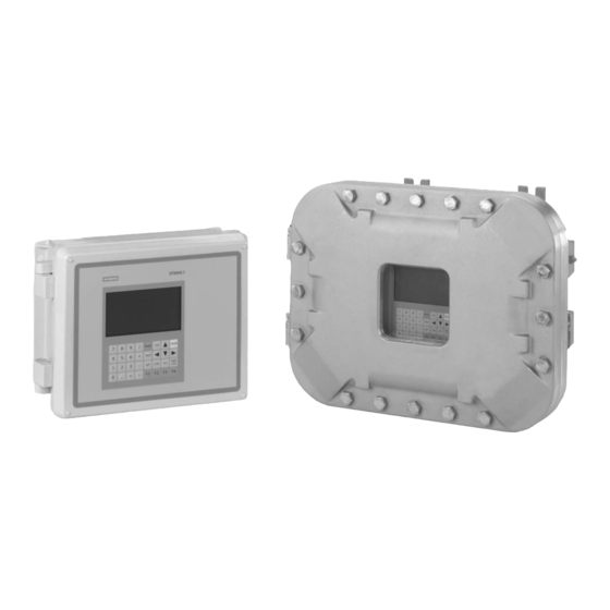
SITRANS FUS1010 IP65 NEMA 4X & IP66 NEMA 7
Gross Volume 7ME353x-2, x=0,3
SITRANS FUH1010 IP65 NEMA 4X & IP66 NEMA 7
Standard Volume 7ME360x-4, x=0,3
Precision Volume 7ME360x-3, x=0,3
Interface Detector 7ME360x-1, x=0,3
SITRANS FUE1010 IP65 NEMA 4X
Gross Volume 7ME3500
Quick Start - January 2013
SITRANS F
Answers for industry.
Advertisement
Table of Contents

Related Manuals for Siemens SITRANS FUS1010


Summary of Contents for Siemens SITRANS FUS1010
- Page 1 Ultrasonic flowmeters SITRANS FUS1010 IP65 NEMA 4X & IP66 NEMA 7 Gross Volume 7ME353x-2, x=0,3 SITRANS FUH1010 IP65 NEMA 4X & IP66 NEMA 7 Standard Volume 7ME360x-4, x=0,3 Precision Volume 7ME360x-3, x=0,3 Interface Detector 7ME360x-1, x=0,3 SITRANS FUE1010 IP65 NEMA 4X...
- Page 3 ___________________ FUS1010 IP65 NEMA 4X Introduction ___________________ Installing/Mounting ___________________ Connecting SITRANS F ___________________ Commissioning Ultrasonic Flowmeters ___________________ FUS1010 IP65 NEMA 4X Troubleshooting & IP66 NEMA 7 ___________________ Quick Start Appendix Operating Instructions 01/2013 A5E03086486-AC...
- Page 4 Note the following: WARNING Siemens products may only be used for the applications described in the catalog and in the relevant technical documentation. If products and components from other manufacturers are used, these must be recommended or approved by Siemens. Proper transport, storage, installation, assembly, commissioning, operation and maintenance are required to ensure that the products operate safely and without any problems.
-
Page 5: Table Of Contents
Table of contents Introduction..............................7 Introduction ............................7 Items supplied ..........................7 Safety Notes...........................8 Installing/Mounting........................... 15 Application Guidelines .........................15 Mounting the Transmitter ......................15 Connecting .............................. 19 Safety notes for connecting ......................19 Transmitter Wiring........................21 3.2.1 Wiring Temperature Sensor to Transmitter .................25 Navigating the Menu ........................28 Programming the Transmitter ......................31 Sensor Installation ........................39 3.5.1... - Page 6 Table of contents Table 5- 1 Troubleshooting Tips........................49 Table 5- 2 Alarm Codes and Descriptions ....................51 Table A- 1 Connection Diagrams and Part Numbers ..................53 Table A- 2 Input/Output Wiring (TB2) - 7ME39400AL00 and 7ME39400AL01 I/O Module (for 7ME3500 or 7ME3530 only) ......................54 Table A- 3 Input/Output Wiring (TB3) - 7ME39400AL00 and 7ME39400AL01 I/O Module ......55 Table A- 4...
- Page 7 Table of contents Figure 3-6 Universal Sensor Label........................35 Figure 3-7 Hi Precision Sensor Label......................36 Figure 3-8 Reflect Mount with Mounting Frames and Spacer Bar ..............40 Figure 3-9 Sensor............................42 Figure 3-10 Sensor Installation ........................42 Figure 3-11 Clamp-on Temperature Sensor ....................44 Figure 3-12 Insert Temperature Sensor ......................45 Figure 3-13 Sensor Cable Connections ......................46...
- Page 8 Table of contents FUS1010 IP65 NEMA 4X & IP66 NEMA 7 Quick Start Operating Instructions, 01/2013, A5E03086486-AC...
-
Page 9: Introduction
Introduction Introduction This Quick Start Guide is for the Siemens SITRANS FUS1010 IP65 (NEMA 4X), FUH1010 IP65 (NEMA 4X), FUE1010 IP65 (NEMA 4X) Dual Channel/Path flow meters and the FUH1010 IP65 (NEMA 4X) Interface Detector. It illustrates a typical setup using D-Series sensors in the Reflect Mode (for Direct Mode see Operating Instruction manual). -
Page 10: Safety Notes
Introduction 1.3 Safety Notes Safety Notes Quick Start Safety Information for Hazardous Areas DANGER Explosion Hazard Death, serious injury or property damage will result if unauthorized and unqualified personnel tamper with equipment. Restrict use and repair to qualified personnel. DANGER Explosion Hazard Death or severe personal injury and/or equipment and property damage will result if proper Hazardous (Classified) Locations installation precautions are not taken. - Page 11 Start shall not become part of or modify any prior or existing agreement, commitment or relationship. The sales contract contains the entire obligation of Siemens. The warranty contained in the contact between the parties is the sole warranty of Siemens. Any statements contained herein do not create new warranties or modify the existing warranty.
- Page 12 Introduction 1.3 Safety Notes Transmitter ● Intrinsically safe connections Class I and II, Division 1, Groups A, B, C, D, E, F and G; ● Nonincendive for Class I, Division 2, Groups A, B, C and D; ● Suitable for Class II Division 2, Groups E, F and G outdoor (Type 4X), Class III (CSA only) ●...
- Page 13 Introduction 1.3 Safety Notes Quick Start Safety Information for Hazardous Areas Note Ratings under this heading apply to specific model families Check Your Model Number: FUS1010 7ME3533, FUH1010 7ME3603 only FM-CSA installation Read, understand and follow all safety instruction on the electronic media provided. This equipment is rated for use in hazardous (classified) locations as stated below and must be installed according to the 1010-443 installation drawing provided on the media.
- Page 14 Introduction 1.3 Safety Notes Transmitter Markings and Explanations ● II (1) G [Ex ia] IIC– Transmitter located in the non-hazardous area with intrinsically safe circuits of category Ex ia, which can be connected to Category 1 Sensors for use in potentially explosive atmosphere containing gases ●...
- Page 15 Ex ia for use in potentially explosive atmosphere containing gases ● IP65 – Ingress protection against solid bodies, rating of dust-tight and against liquid, rating of water jets See also Contacts (http://www.siemens.com/processinstrumentation/contacts) FUS1010 IP65 NEMA 4X & IP66 NEMA 7 Quick Start Operating Instructions, 01/2013, A5E03086486-AC...
- Page 16 Introduction 1.3 Safety Notes FUS1010 IP65 NEMA 4X & IP66 NEMA 7 Quick Start Operating Instructions, 01/2013, A5E03086486-AC...
-
Page 17: Installing/Mounting
Installing/Mounting Application Guidelines Basic Requirements ● Determine pipe material and dimensions. ● Avoid vertical pipes flowing in a downward direction. ● Avoid installation of sensors on the top and bottom of horizontal pipes, if possible. ● Select a location with the longest straight run of pipe. ●... - Page 18 Installing/Mounting 2.2 Mounting the Transmitter Pipe Mounting For installation on 2-inch (6 cm) mounting pipe use Pipe Mount Kit CQO:1012NMB-1 (optional - see catalog). See figure below. Note Pipe mounting kit CQO:1012NMB-1 is not available for IP66 NEMA 7 enclosures. ①...
- Page 19 Installing/Mounting 2.2 Mounting the Transmitter NOTICE Weather Seal Malfunctions Incorrect installation of weather seals may result in failure to meet to IP65 standards and damage to the equipment. Install weather tight seals at all unused holes using proper cable conduit and close additional holes to IP65 standards.
- Page 20 Installing/Mounting 2.2 Mounting the Transmitter FUS1010 IP65 NEMA 4X & IP66 NEMA 7 Quick Start Operating Instructions, 01/2013, A5E03086486-AC...
-
Page 21: Connecting
Connecting Safety notes for connecting Use in hazardous locations DANGER Explosion Hazard Death or severe personal injury and/or equipment and property damage will result if proper Hazardous (Classified) Locations installation precautions are not taken. Restrict use and repair to qualified personnel. Only qualified personnel may carry out work on the electrical connections. - Page 22 Connecting 3.1 Safety notes for connecting DANGER Explosion Hazard "Flameproof enclosure" type of protection Only open devices with type of protection "Flameproof enclosure" (e.g. FUT1010 NEMA 7) in hazardous areas when the power to the device is turned off, otherwise there is a risk of explosion.
-
Page 23: Transmitter Wiring
Connecting 3.2 Transmitter Wiring WARNING Electrical Voltage Hazard Incorrect device connections may result in death or severe personal injury and/or equipment and property damage. Only commission the device after the device has been properly connected and, if required, closed. Transmitter Wiring Connecting Power DANGER Electrical Shock Hazard... - Page 24 Connecting 3.2 Transmitter Wiring ① ⑥ Power Supply Wire Entry ② ⑦ Power Supply Access Cover Strip length 8mm (0.31 in) ③ ⑧ Fuse F1 Wire Clamp Screws ④ ⑨ Input Power Conn. J10 Ferrite power cord ⑤ Connector mounting screws Figure 3-1 Input Power Plug (J10) Wiring 4.
- Page 25 Connecting 3.2 Transmitter Wiring 8. Replace access cover. Make sure Keypad Enable switch is in the "Enable" position (see below). ① Keypad Enable Switch 9. If installing a Temperature Sensor board, go to Wiring Temperature Sensor to Transmitter (Page 25). If not, go to step 10. CAUTION Power Supply Damage Improper power connections will damage power supply and may result in serious injury.
- Page 26 Connecting 3.2 Transmitter Wiring 12. Within 10 seconds of power-up the transmitter main display will become active and a typical Siemens graphic will appear. The screen also identifies the software version of the unit as shown below. ① Software Version (xx.xx.xx) 13.
-
Page 27: Wiring Temperature Sensor To Transmitter
Connecting 3.2 Transmitter Wiring 3.2.1 Wiring Temperature Sensor to Transmitter Wiring Temperature Sensor to the Analog Input Module DANGER Hazard Voltage Contact with exposed wiring will lead to fire, electric shock, or serious personal injury. Set transmitter and instrumentation power to OFF when inserting or removing the Analog Input Module, or when making connections to TB1, TB2, TB3 and TB4. - Page 28 Connecting 3.2 Transmitter Wiring Figure 3-3 Single Channel Temperature Sensor Inputs ① ⑥ Black Short Terminals 1 and 4 (For FUE1010 - TB2 is used for another Temperature sensor.) ② Orange ⑦ Ground Terminals 2 and 3 to Terminal 5 ③...
- Page 29 Connecting 3.2 Transmitter Wiring Wiring Temperature Sensor Board 1. Using a flat-blade screwdriver, loosen Terminal Block TB1 and TB2 screws. 2. Wire the RTD liquid 992EC temperature cable as shown in the table below: 992EC Series Cable Terminal TB1 Wire #1 (Black) To TB1--1 Wire #2 (Orange) To TB1--2...
-
Page 30: Navigating The Menu
Connecting 3.3 Navigating the Menu Note If analog input is used for temperature, this will take priority over clamp-on RTD measurement. WARNING Electrical Shock Hazard Certain parts inside the device carry dangerous high voltage and may result in electric shock, or serious personal injury. The transmitter must be grounded and the top cover closed before applying power to the device. -
Page 31: Table 3- 1 Keypad Function Chart
Connecting 3.3 Navigating the Menu 7 8 9 MENU ENTER 4 5 6 HELP 1 2 3 DATA CTRL Figure 3-4 Key Pad Note Use <Left Arrow> key to return to previous menus. Table 3- 1 Keypad Function Chart Keys Description MENU Press to activate the Installation Menu. - Page 32 Connecting 3.3 Navigating the Menu ① ⑤ Menu Cell Data (left-hand column) Current Selected Measurement Channel ② ⑥ Highlighted Menu Cell Site Name Identified ③ ⑦ Menu Prompt Line (Reverse Video) Highlighted Data ④ ⑧ Current Selected Meter Type Menu Cell Data (right-hand column) Figure 3-5 Typical Installation Menu Screen FUS1010 IP65 NEMA 4X &...
-
Page 33: Programming The Transmitter
Connecting 3.4 Programming the Transmitter Programming the Transmitter Select Language and Units Note Before creating a site select a Language and then English or Metric units from the [Meter Facilities] menu. Note To select English or metric units: In [Meter Type] menu, scroll to [Meter Facilities] menu. Press <Right Arrow>... - Page 34 Connecting 3.4 Programming the Transmitter Create a Site 1. At the [Channel Setup] menu press the <Right Arrow>. Note Before proceeding make sure that English or Metric units have been selected. 2. Press the <Down Arrow> to select the [Create/Name Site] and enter a Site name. 3.
- Page 35 Connecting 3.4 Programming the Transmitter Select Pipe Class 1. Press the <Right Arrow> to select [Pick Pipe Class]. Press <Right Arrow> again and scroll to desired Pipe Class. 2. Press <ENTER> to select. 3. Pre-programmed Pipe Size and relevant pipe parameters will appear in menu cells. Press <Right Arrow>...
-
Page 36: Table 3- 2 Pipe Configuration Option List Definitions
Connecting 3.4 Programming the Transmitter Select Pipe Configuration 1. Scroll down to [Pipe Config] and press the <Right Arrow>. 2. Select a configuration that approximates the conditions upstream of your sensor mounting location. (Refer to the definitions below.) 3. Press <ENTER> to save selection. ①... - Page 37 Connecting 3.4 Programming the Transmitter Typical Sensor Labels ① Universal sensor model number ② Sensor size Figure 3-6 Universal Sensor Label FUS1010 IP65 NEMA 4X & IP66 NEMA 7 Quick Start Operating Instructions, 01/2013, A5E03086486-AC...
- Page 38 Connecting 3.4 Programming the Transmitter ① Hi Precision sensor model number ② Sensor size Figure 3-7 Hi Precision Sensor Label Sensor Selection The following is a typical sensor selection procedure. 1. Press <Left Arrow> to return to Main Menu. At the [Meter Type], press the <Right Arrow> and then <ENTER>.
- Page 39 Connecting 3.4 Programming the Transmitter 5. The drop down menu lists the following sensor selections: – 1011 Universal – 1011HP-T1 - Usable -40 to 120°C, recommended for Ø Temperature <40°C; Standard. – 1011HP-T2 - Usable -40 to 120°C, recommended for Ø Temperature >40°C - <80°C; Named as high temperature.
- Page 40 Connecting 3.4 Programming the Transmitter Save/Rename Site procedure Whenever new site configurations are added to an existing site that site must be saved again to retain the new site changes. 1. To save all programmed data to site, press <Left Arrow> and then scroll up to [Channel Setup].
-
Page 41: Sensor Installation
Connecting 3.5 Sensor Installation Sensor Installation 3.5.1 General information Reflect and Direct Mounting Modes Reflect and Direct mounting modes are supported for clamp-on sensors. The transmitter recommends a mounting mode after analyzing your pipe and liquid data entries. This Quick Start illustrates a typical sensor setup using the Reflect Mode. - Page 42 Connecting 3.5 Sensor Installation Before beginning refer to the Reflect Mount Installation diagram example below. ① ⑤ Optional: On larger pipes, multiple lengths Space Bar Platform & Clamping Screw of straps can be linked together to surround pipe ② ⑥ Mounting Strap positioned around Space Bar (Front View) Mounting Frame...
- Page 43 Connecting 3.5 Sensor Installation 3. Wrap a Mounting Strap around the pipe. Make sure to position it so there is easy access to the Mounting Strap Adjusting Screw. 4. At the mounting location, place the Mounting Frame/Spacer Bar Assembly on the pipe so that it rests on the top of the pipe.
- Page 44 Connecting 3.5 Sensor Installation Installing the Sensor 1. Take either sensor and apply a continuous lengthwise 3mm (1/8-inch) bead of coupling compound across the center of the sensor emitting surface. ① ④ F-Connector Front Face ② ⑤ Angled Edge Emitting Surface ③...
-
Page 45: Mounting Temperature Sensors
Connecting 3.5 Sensor Installation 2. Slide sensor into a mounting frame back end first aligning the angled edge of the sensor with the angled edge of the mounting frame. Keep sensor from making contact with the pipe until it butts up against the mounting frame stop. Push sensor down to mate with pipe. - Page 46 Connecting 3.5 Sensor Installation ① ③ 7ME39600CR 992EC Series Cable Thermal Couplant ② ④ Clamp-on Temperature Sensor (Matched Pipe pair required for FUE1010) ⑤ Mounting Assembly Figure 3-11 Clamp-on Temperature Sensor FUS1010 IP65 NEMA 4X & IP66 NEMA 7 Quick Start Operating Instructions, 01/2013, A5E03086486-AC...
-
Page 47: Sensor Wiring
Connecting 3.6 Sensor Wiring Clamp-on Sensors Clamp-on style sensors are mounted on the surface of the monitored pipe using series mounting assemblies. Apply a generous quantity of the thermal couplant provided to the tip of the sensor and attach it securely to the cleaned pipe surface with the proper mounting assembly. - Page 48 Connecting 3.6 Sensor Wiring 3. Replace the Cable Strain Relief bracket. Close top cover. 4. Proceed to Commissioning (Page 47). ① ⑤ Transmitter Input Module To CH-2 UP ② ⑥ Sensor Cables Connected to Transmitter To CH-1 DN ③ ⑦ Cable Strain Relief Bracket To CH-1 UP ④...
-
Page 49: Commissioning
Commissioning Commissioning Note Refer to [Programming the Transmitter] (Page 31) if needed. 1. Scroll down to [Install Sensor] and press <Right Arrow>. 2. Scroll down to [Install Complete]. Press the <Right Arrow> and select [Install]. Press <ENTER>. The flow meter will go through its drives. Figure 4-1 Final Setup Figure 4-2... - Page 50 Commissioning 4.1 Commissioning 5. Press the <MENU> key. 6. Press the <Right Arrow> and then <ENTER> to save the site data. 7. The flow meter is now ready to report flow. 100.0 14.35 354.6597 14.27 31.74 See also Refer to I/O Connection Tables (Page 53) for input/output wiring and the Span Data manual section for data spanning procedures.
-
Page 51: Troubleshooting
The following is list of troubleshooting tips and messages that you may encounter. They include explanations and, in some cases, a recommended action. If a problem seems unsolvable, contact your local Siemens office or regional Ultrasonic Flow Representative for expert help at: http://www.automation.siemens.com/partner (http://www.automation.siemens.com/partner). - Page 52 Troubleshooting 5.1 Troubleshooting Error or Message Probable Cause Solution Re-space Index The measured liquid sonic velocity (Vs) is Ensure proper pipe dimensions and/or Liquid more than +/- 25% of the average Vs range. data entries are correct. Properly enter correct Sensor Size into the ...
-
Page 53: Alarm Codes
5.2 Alarm Codes Note If you receive a Detection Fault message, it is strongly recommended that the Technical Service Department (http://www.automation.siemens.com/partner) be contacted. Alarm Codes The following alarm codes appear on the main display of the flow meter. Table 5- 2... - Page 54 Troubleshooting 5.2 Alarm Codes 68.10 112.38 30.0 -30.0 9/26 12:45 ① Alarm Codes FUS1010 IP65 NEMA 4X & IP66 NEMA 7 Quick Start Operating Instructions, 01/2013, A5E03086486-AC...
-
Page 55: Appendix
Appendix I/O Connections and Wiring Terminal Block Wiring - 7ME39400AL00 and 7ME39400AL01 I/O Module (Refer to manual drawing 1010N-2-7 sheet 2 of 2) These connection diagrams apply to the part numbers listed below. Table A- 1 Connection Diagrams and Part Numbers 1010N-2-7 (Sheet 2 of 2) Drawing FUS1010 7ME3530, 7ME3533... - Page 56 Appendix A.1 I/O Connections and Wiring Table A- 2 Input/Output Wiring (TB2) - 7ME39400AL00 and 7ME39400AL01 I/O Module (for 7ME3500 or 7ME3530 only) Pin# Signal Description Definition Function Vo1+ Meter process variables 0-10 Volt Analog Output System outputs assignable and scalable are assigned to individual to flow related parameters.
- Page 57 Appendix A.1 I/O Connections and Wiring Table A- 3 Input/Output Wiring (TB3) - 7ME39400AL00 and 7ME39400AL01 I/O Module Pin# Signal Definition Description Function Function Function Function Single Dual Channel Dual Path Dual Path Channel Only K1 A Relay 1 Normally Relay 1 Alarm or Alarm or...
- Page 58 Appendix A.1 I/O Connections and Wiring K1-A *K1-B K1-C K2-A *K2-B K2-C K3-A *K3-B K3-C K4-A *K4-B K4-C Note Relays shown in Power OFF position, which is the same as the alarm assertion position. *7ME39400AL00 Mercury Relay only available with Normally Open. Terminal Block Wiring - 7ME39400AL03 and 7ME39400AL04 Expanded I/O Module (Refer to manual drawing 1010N-7-7 sheet 2 of 2) These connection diagrams apply to the part numbers listed below.
- Page 59 Appendix A.1 I/O Connections and Wiring Figure A-2 7ME39400AL03 and 7ME39400AL04 Expanded I/O Module Table A- 5 Input/Output Wiring (TB2) - 7ME39400AL03 and 7ME39400AL04 Expanded I/O Module Pin# Signal Definition Description Function Dual/Quad Path Only Chassis Ground Chassis Ground Cable Shield Terminations Chassis Ground Chassis Ground Cable Shield Terminations...
- Page 60 Appendix A.1 I/O Connections and Wiring ① ④ TB2-11 - POS [+] Total OC 4-20mA Load 1k ohm (max) TB2-12 - POS [+] Total TTL ② ⑤ TB2-9 - NEG [-] Total OC 0-10V Load 10k ohm (min) TB2-10 - NEG [-] Total TTL ③...
- Page 61 Appendix A.1 I/O Connections and Wiring Table A- 6 Input/Output Wiring (TB3) - 7ME39400AL03 and 7ME39400AL04 Expanded I/O Module Pin# Signal Definition Description Function Function Dual Path Only Quad Path Only K1 A Relay 1 Normally Open Relay 1 Alarm or control functions Alarm or control set by CH 3 functions set by...
- Page 62 Appendix A.1 I/O Connections and Wiring Note Relays shown in Power OFF position, which is the same as the alarm assertion position. *7ME39400AL03 Mercury Relay only available with Normally Open. Table A- 7 Input/Output Wiring (TB4) - 7ME39400AL03 and 7ME39400AL04 Expanded I/O Module Pin# Signal Definition...
- Page 63 Appendix A.1 I/O Connections and Wiring Terminal Block Wiring - 7ME39400AL04 Expanded I/O Module (Refer to manual drawing 1010N-7-7 sheet 2 of 2) These connection diagrams apply to the part numbers listed below. Table A- 8 Connection Diagrams and Part Numbers 1010N-7-7 (Sheet 2 of 2) Drawing FUH1010 7ME3600, 7ME3603...
- Page 64 Appendix A.1 I/O Connections and Wiring Table A- 9 Input/Output Wiring (TB2) - 7ME39400AL04 Expanded I/O Module Pin# Signal Definition Description Function Dual/Quad Path Only Chassis Ground Chassis Ground Cable Shield Terminations Chassis Ground Chassis Ground Cable Shield Terminations POS [+] Total TTL Totalizer Pulses, scalable POS [+] Total TTL POS [+] Total OC...
- Page 65 Appendix A.1 I/O Connections and Wiring Table A- 10 Open Collector User Resistor Recommendations User Supply External Resistor Expected Recommended Resistor Wattage (Watts) Voltage (VDC) (Ohms) Current Draw (mA) 18.5 17.6 17.6 1000 1500 1800 15.5 1 1/4 2400 1 1/4 Note TB2-9 and TB2-11 are Open Collector Outputs that require external pull-up resistors for operation.
- Page 66 Appendix A.1 I/O Connections and Wiring Pin# Signal Definition Description Function Function Dual Path Only Quad Path Only Digital Return (GND) DGND K4 A Relay 4 Normally Open Relay 4 Alarm or control Alarm or control functions set by functions set by CH 5. K4 B Relay 4 Normally Closed CH 3.
- Page 67 Appendix A.1 I/O Connections and Wiring Table A- 12 Input/Output Wiring (TB4) - 7ME39400AL04 Expanded I/O Module Pin# Signal Function Description No Connection No Connection No Connection No Connection AUX 103+ Isolated Loop Supply Connect +30V max. Loop Supply here AUX 103- Loop-Powered 4-20mA PGEN 1 Data Presented as 4-20mA...
- Page 68 Appendix A.1 I/O Connections and Wiring Terminal Block Wiring - 7ME39406ML00 I/O Module (4-Channel) FUS1010, 7ME35309 only (Refer to manual drawing 1010N-8MS2-7 (sheet 2 of 2) Table A- 13 Input/Output Wiring (TB3) - 7ME39406ML00 I/O Module (4-Channel) Pin# Signal Function Description Iout 1+ Isolated Loop Supply...
- Page 69 Appendix A.1 I/O Connections and Wiring Terminal Block Wiring - 7ME39404SB00 - Analog Input Module - 2 Channel/Dual Path (Refer to manual drawing 1010N-5DS2-7) These connection diagrams apply to the part numbers listed below. Table A- 14 Connection Diagrams and Part Numbers 1010N-5DS2-7 Drawing FUS1010 7ME3530, 7ME3533...
- Page 70 Appendix A.1 I/O Connections and Wiring Table A- 15 Input/Output Wiring TB1 7ME39404SB00 - Analog Input Module (2 Chan/Dual Path) Color Function Description Wiring/Cable TB1-1 Black RTD Current High RTD Temperature measurement T1 or AWG. 14 - 24 / Channel 1 Ts (Supply Temperature) 1000 Ft max w/o TB1-2 White...
- Page 71 Appendix A.1 I/O Connections and Wiring Table A- 19 Input/Output Wiring TB5 7ME39404SB00 - Analog Input Module (2 Chan/Dual Path) Function Description Behavior Load Wiring/Cable TB5-1 AUX. 1 IN Iin1 Input Analog current 4 to 20 mA 200 Ω AWG. 14-24 / input 100 ft.
- Page 72 Appendix A.1 I/O Connections and Wiring Terminal Block Wiring - 7ME39400SA00 - Analog Input Module - Single Channel (Refer to manual drawing 1010N-5S2-7) These connection diagrams apply to the part numbers listed below. Table A- 20 Connection Diagrams and Part Numbers 1010N-5S2-7 Drawing FUS1010 7ME3530, 7ME3533...
- Page 73 Appendix A.1 I/O Connections and Wiring Table A- 22 Input/Output Wiring TB2 7ME39400SA00 - Analog Input Module Color Function Description Wiring/Cable TB2-1 Black RTD Current High RTD Temperature measurement T2 or AWG. 14 - 24 / Channel 1 Tr (Return Temperature) 1000 Ft max w/o TB2-2 White...
-
Page 74: Technical Data
Appendix A.2 Technical Data ① ⑥ Black Short Terminals 1 and 4 (For FUE1010 - TB2 is used for another Temperature sensor.) ② ⑦ Orange Ground Terminals 2 and 3 to Terminal 5 ③ ⑧ To Sensor ④ ⑨ 7ME39600CR (992EC) Series Cable ⑤... - Page 75 Appendix A.2 Technical Data Input ● Flow Range: ± 12 m/s (± 40 ft/s), bidirectional ● Flow sensitivity: 0.0003 m/s (0.001 ft/s), flow rate independent Accuracy ● Calibratable accuracy: ± 0.15% to 0.3% of flow, depending on version ● Batch repeatability: ± 0.05% of flow, maximum ●...
- Page 76 Please note the following: ● The user is responsible for all changes and repairs made to the device. ● All new components must be provided by Siemens Industry, Inc. ● Restrict repair to faulty components only. ● Do not re-use faulty components.
- Page 79 Select Data Enter From List Data Display Enter From List Time Base Enter From List Stripchart Clear Yes/No This Menu Chart applies to: MLFB - 7ME3530 7ME3533 Siemens Industry, Inc. Industry Automation Division CoC Ultrasonic Flow Hauppauge, New York Web: www.usa.siemens.com...
- Page 80 FUS1010 IP65 (NEMA 4X) Installation Menu Chart LEVEL A LEVEL B LEVEL C/D LEVEL E (see manual) LEVEL F LEVEL G Logger Setup Logger Mode Enter From List Logger Data Enter From List Logger Interval Enter From List Logger Events Enter From List Display Logger Enter From List...
- Page 81 New Point Table Active 1 No/Yes Clear Table 1 No/Yes Calib. Table 2 Same as Calib. Table 1 Siemens Industry, Inc. Calib. Table 3 Same as Calib. Table 1 Industry Automation Division CoC Ultrasonic Flow Hauppauge, New York Web: www.usa.siemens.com...
- Page 82 FUH1010 IP65 (NEMA 4X) Installation Menu Chart LEVEL A LEVEL B LEVEL C LEVEL D (see manual) LEVEL E LEVEL F Display Setup Select Data Enter From List Data Display Enter From List Time Base Enter From List Stripchart Clear Yes/No Logger Setup Logger Mode...
- Page 83 Calib. Table 3 Same as Calib. Table 1 Display Setup Select Data Enter From List Data Display Enter From List Siemens Industry, Inc. Time Base Enter From List Industry Automation Division Stripchart Clear Yes/No CoC Ultrasonic Flow Hauppauge, New York...
- Page 84 FUH1010 IP65 (NEMA 4X) Installation Menu Chart LEVEL A LEVEL B LEVEL C LEVEL D (see manual) LEVEL E LEVEL F Logger Setup Logger Mode Enter From List Logger Data Enter From List Logger Interval Enter From List Logger Events Enter From List Display Logger Enter From List...
- Page 85 Enter From List 7ME3603-1or -2 Site Setup Data Enter From List Test Facilities Enter From List Print Site Setup No/Yes Site Created: View Only mm.dd.yy hh.mm.ss Siemens Industry, Inc. Industry Automation Division CoC Ultrasonic Flow Hauppauge, New York Web: www.usa.siemens.com...
- Page 86 FUH1010 IP65 (NEMA 4X) Installation Menu Chart LEVEL A LEVEL B LEVEL C/D LEVEL E (see manual) LEVEL F LEVEL G Meter Facilities Preferred Units English/Metric Table Setups Pipe Table Create/Edit Pipe Enter From List Delete Pipe Enter From List Transducer Type Enter From List Logger Control...
- Page 87 Enter From List MLFB - 7ME3500 Display Setup Select Data Enter From List Data Display Enter From List Time Base Enter From List Stripchart Clear Yes/No Siemens Industry, Inc. Industry Automation Division CoC Ultrasonic Flow Hauppauge, New York Web: www.usa.siemens.com...
- Page 88 FUE1010 IP65 (NEMA 4X) Installation Menu Chart LEVEL A LEVEL B LEVEL C/D LEVEL E (see manual) LEVEL F LEVEL G Logger Setup Logger Mode Enter From List Logger Data Enter From List Logger Interval Enter From List Logger Events Enter From List Display Logger Enter From List...
Need help?
Do you have a question about the SITRANS FUS1010 and is the answer not in the manual?
Questions and answers