Table of Contents
Advertisement
Quick Links
Advertisement
Table of Contents

Related Manuals for Extron electronics MPS 602


Summary of Contents for Extron electronics MPS 602
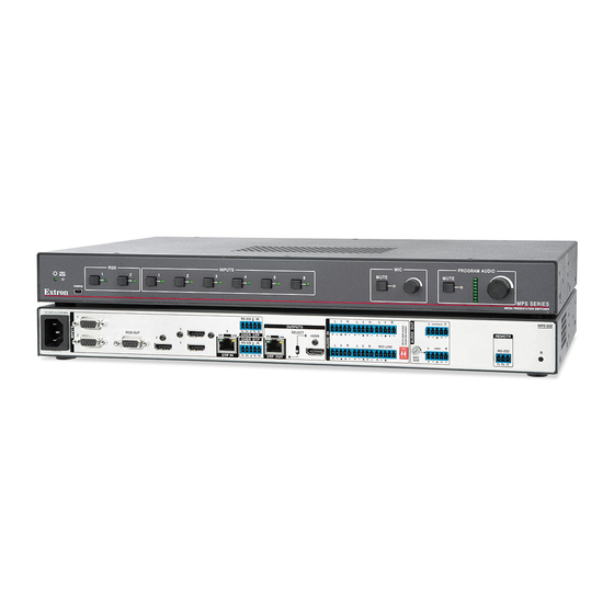
- Page 1 User Guide Switchers MPS 602 Media Presentation Switcher 68-2358-01 Rev. C 06 16...
-
Page 2: Safety Instructions
Safety Instructions Safety Instructions • English Istruzioni di sicurezza • Italiano WARNING: This symbol, , when used on the product, is intended to AVVERTENZA: Il simbolo, , se usato sul prodotto, serve ad alert the user of the presence of uninsulated dangerous voltage within avvertire l’utente della presenza di tensione non isolata pericolosa the product’s enclosure that may present a risk of electric shock. - Page 3 より 『Extron Safety www.extron.com and Regulatory Compliance Guide』 (P/N 68-290-01) をご覧ください。 Copyright © 2016 Extron Electronics. All rights reserved. Trademarks All trademarks mentioned in this guide are the properties of their respective owners. The following registered trademarks®, registered service marks( ), and trademarks( ) are the property of RGB Systems, Inc.
- Page 4 FCC Class A Notice This equipment has been tested and found to comply with the limits for a Class A digital device, pursuant to part 15 of the FCC rules. The Class A limits provide reasonable protection against harmful interference when the equipment is operated in a commercial environment.
-
Page 5: Conventions Used In This Guide
Conventions Used in this Guide Notifications The following notifications are used in this guide: WARNING: Potential risk of severe injury or death. AVERTISSEMENT : Risque potentiel de blessure grave ou de mort. CAUTION: Risk of minor personal injury. ATTENTION : Risque de blessure mineure. ATTENTION: •... -
Page 7: Table Of Contents
Contents Introduction Configuration Software ............1 ........23 About this User Guide ........1 Installing the Software ........23 About the MPS 602 ..........1 Starting the Software ........24 Features ............. 1 Device Discovery Panel ......... 25 Offline Device Preview ........26 Using the Software and Device Menus ..... - Page 8 MPS 602 • Contents viii...
-
Page 9: Introduction
CATx cable up to 330 feet (100 meters). The MPS 602 also includes several audio switching and processing features, available power amplification, plus flexible control options for complete switching and distribution with local and remote display support. - Page 10 RGB video on 15-pin HD, one fixed audio output on captive screw, one variable stereo audio output on captive screw, speaker outputs on 5 mm, 4-pole captive screw connector (MPS 602 SA) or on 5 mm, 2-pole captive screw connector (MPS 602 MA).
- Page 11 2 x 50 watts @ 4 ohms; 2 x 25 watts @ 8 ohms • 1 x 100 watts @ 70 volts — The MPS 602 SA offers a stereo power amplifier with • 50 watts per channel into 4 ohms and 25 watts per channel into 8 ohms, while the MPS 602 MA offers a mono 70 volt power amplifier with 100 watts rms output.
- Page 12 MPS 602 Application Diagram Figure 1 shows a typical application. Extron TCP/IP TLP Pro 1022TV Network Extron 10" Tabletop TouchLink Pro MPS 602 SA Touchpanel Ethernet Media Presentation Ethernet Switcher Extron IPL 250 -2 3 Ω RS-232 R AM 8 Ω...
-
Page 13: Installation
The MPS 602 is housed in a 1U, full rack width rack- or desk-mountable metal enclosure. The switcher can also be surface-mounted under a table, desk, or podium, or on a wall (see Mounting the Switcher on page 55 for additional mounting details). figure 2 Rear Panel Connections MPS 602 SA 100-240V 1.0A MAX RS-232 VARIABLE OUTPUTS... -
Page 14: Video Input And Output
DTP Input and Output NOTE: The MPS 602 can communicate with both DTP 230 and DTP 330 transmitters and receivers. When connected to a DTP 230 device, the connection is limited to the DTP 230 maximum distance (230 feet, 70 m). -
Page 15: Analog Audio Input
Analog Audio Input Audio input group (see figure 2 on page 5) —Five 3.5 mm, 5-pole captive screw connectors provide analog audio input to the switcher. Inputs 1-5 accept either balanced or unbalanced audio. The audio level of each input is adjusted using the configuration software or using the front panel (see Audio Gain and Attenuation Adjustments... -
Page 16: Program Audio Output
Mute HDMI Audio and Phantom Power (see figure 2 on page 5) — Two 2-position DIP switches. The MUTE HDMI AUDIO switch (see figure 6) mutes the HDMI embedded audio on both the HDMI output and the DTP output when the switch is in the UP position. If your microphone requires phantom power, the PHANTOM POWER switch selects +48 V phantom power for the mic input when in the UP position. -
Page 17: Control Ports
Be sure to observe the correct polarit either side. Do not tin the wires! 4 Ω 8 Ω MPS 602 MA MPS 602 SA Figure 9. Amplified Output Connector Wiring Control Ports RS-232 remote — A 3-pole, 3.5 mm captive screw connector for connection of a host computer or a controller using SIS or Windows-based control software. -
Page 18: Twisted Pair Recommendations
Twisted Pair Recommendations Supported Cables The MPS 602 is compatible with CAT 5e, 6, 6a, and 7 shielded twisted pair (F/UTP, SF/UTP, and S/FTP) and unshielded twisted pair (U/UTP) cable. ATTENTION: • Do not use Extron UTP23SF-4 Enhanced Skew-Free AV UTP cable or STP201 cable to link the XTP products or with DTP transmitters or receivers. -
Page 19: Lockit Hdmi Cable Lacing Bracket
LockIt HDMI Cable Lacing Bracket LockIt lacing brackets are provided to secure the HDMI cables to the rear panel connectors as shown in figure 11, below. The configuration of the HDMI connectors and supporting fasteners on the MPS 602 rear panel require using a top mount installation for HDMI input 3 and a single or stacked side mount installation for HDMI inputs 4 and 5. -
Page 20: Cabling The Mps 602 Switcher
The MPS switcher can be connected to as many as six input devices. It can output to one of two outputs (HDMI or DTP). Follow the steps below and the installation example (see MPS 602 Application Diagram on page 4). Turn off power to the MPS switcher and all devices that are connected to it. -
Page 21: Operation
Operation This section discusses how to connect, configure, and operate the MPS 602. Topics include: • Front Panel Operation • Microphone Controls Front Panel Security Lockout (Executive Mode) EDID Minder • • • HDMI/DTP Embedded Audio Output • HDCP Program Audio • figure 12 Front Panel Operation A B C... -
Page 22: Auto-Input Switching
HDMI (digital input group) — HDMI input buttons 3, 4, and 5 select the source for the HDMI or DTP output (see figure 2, and on page 5) and the corresponding audio switcher section. The Indicators to the right of each button (when lit) indicate the selected input. -
Page 23: Front Panel Security Lockout (Executive Mode)
Program Audio Level Indicator (see figure 13 on page 14) — Stacked LEDs indicate the program audio volume level. All segments unlit indicate no (0) volume. As volume increases, the segments illuminate incrementally from the bottom and stay lit as illustrated in the table below. As volume decreases, the Indicators go out in the reverse order. -
Page 24: Hdmi/Dtp Embedded Audio Output
To toggle through the Executive modes: Press and hold the RGB input 1 button (see figure 14, ) for more than 3 seconds. Press and release the digital inputs input 1 button ( ). Each press toggles to the next Executive mode as follows: If Executive mode is not active (Exec Mode indicator off, ), the switcher toggles to Executive mode 1, the Mic Mute indicator flashes three times ( ), and the... -
Page 25: Program Audio Breakaway
Program Audio Breakaway Program audio breakaway allows routing of the audio signal from any input to the program audio output independently from the input video selection. It is available by software control only (see Program audio breakaway on page 51 for SIS commands and see Breakaway Analog Audio check box (Analog Inputs 1 and 2) on page 35 for PCS control). -
Page 26: Audio Gain And Attenuation Adjustments
Audio Gain and Attenuation Adjustments Front Panel LEDs Each audio input level (analog inputs 1 through 5 only) is adjusted from the front panel over a range of -18 dB to +24 dB. The adjustments normalize the input audio levels so that output volume is consistent for all inputs. -
Page 27: Microphone Controls
Microphone Controls Mic Volume and Mute Mic volume and mute are controlled from the front panel (see figure 15). The mic MUTE button ( ) toggles the mic input on and off. The corresponding red Indicator ( ) lights when mic volume is muted. When the mic input is unmuted, it is mixed with the program audio output at a level set by the mic volume rotary encoder ( ). -
Page 28: Edid Minder
EDID Minder The digital and analog groups feature EDID Minder, ensuring that each input source reads the EDID of the output display even when the input is not selected. The result is the video source powers up properly and reliably outputs content when selected. The EDID remains in the selected mode (automatic or user assigned) even after loss of power. - Page 29 Native Video Variable Refresh Rate Type Audio Resolution Format 800 x 600 60 Hz 1024 x 768 60 Hz 1280 x 720 60 Hz 1280 x 768 60 Hz 1280 x 800 60 Hz 1280 x 1024 60 Hz 1360 x 768 60 Hz 1366 x 768 60 Hz...
-
Page 30: Hdcp
Native Variable Refresh Resolution Autodetect (VGA Output) Autodetect (HDMI/DTP Output) User loaded slot 1 User loaded slot 2 User loaded slot 3 User loaded slot 4 User loaded slot 5 User loaded slot 6 If the display connected to the RGB (VGA) output of the switcher does not support DDC, or the switcher does not obtain EDID from the output, the default resolution (EDID 3) is used. -
Page 31: Configuration Software
PCS Download from the Extron Website On the Extron website, select the Download tab (see figure 16, On the Download page, on the left sidebar, click the PCS link ( On the PCS page, click Download ( MPS 602 • Configuration Software... -
Page 32: Starting The Software
) and assists with the PCS software operation. The second, accessed from the device tab after the connecting to the device (see Device Menu - Device Help on page 30) provides assistance with the connected device user interface. MPS 602 • Configuration Software... -
Page 33: Device Discovery Panel
) to sort the category in ascending or descending order. To connect to a device: Click the Device Discovery tab ( Select the desired device ( ), (the device row is high-lighted). Click Connect ( ). A new device configuration tab opens. MPS 602 • Configuration Software... -
Page 34: Offline Device Preview
MPS 602 MA MPS 602 SA PVS 405D Figure 20. New Configuration File Dialog Box (MPS 602 Selected) Select the desired device model from the Device Models list ( Click Configure ( ). A new offline device configuration tab opens. -
Page 35: Using The Software And Device Menus
Figure 22. Device Menu (MPS 602 SA Shown) Disconnect This option disconnects the PCS program and closes the device tab. - Page 36 ) to return the name to the factory default. Device Menu - Reset Device From the Device drop-down list, select Reset Device... (see figure on the previous page). The connected device resets to factory defaults. MPS 602 • Configuration Software...
- Page 37 Update Firmware dialog with the file (see figure 27, Figure 27. Update Firmware Dialog, Firmware File Selected Click Update ( ). A progress bar follows the firmware upload to the device. The dialog closes upon completion and verification of a successful update. MPS 602 • Configuration Software...
- Page 38 Device Menu - Device Help figure Click MPS 602 Help (see on page 27) to open the MPS 602 specific Help file. The Help file contains configuration and operating instructions that apply specifically to the MPS 602. Device Menu - About This Module...
-
Page 39: Software Menu
This option displays a general overview of where to find features in the PCS framework. Click Software Menu>Tutorial (see figure 30, ). The Tutorial dialog opens. Click I Get It! to close the dialog box. MPS 602 • Configuration Software... - Page 40 Exit Dialog Box If necessary, click Close Session(s) and Exit ( ) to disconnect the software from connected devices, close all offline device tabs, and close the software. Click Cancel ) to leave the software open. MPS 602 • Configuration Software...
-
Page 41: Device Configuration
Audio Config – Two panels configure the selected input format and gain and provide adjustment for the mic input level, program output volume, and talk-over threshold and level. General Settings − provides configuration of the device name, front panel lockout mode, and Auto-input switching. MPS 602 • Configuration Software... -
Page 42: Av Controls Panel
Click an Analog Video Input button ( ) to switch that input to the output. As a new input is selected, the indicator Indicator lights green. If there is no active input, the indicator remains gray. MPS 602 • Configuration Software... - Page 43 ) to mute both video and audio. The button turns red, along with the Video Mute and Audio Mute buttons. To unmute or unfreeze any signal, click the appropriate button. The button reverts to the default color, indicating the signal has been unmuted or unfrozen. MPS 602 • Configuration Software...
-
Page 44: Configuration Pages
(inputs 3 to 6). This feature determines if a digital available signal type. input reports as an HDCP authorized sink to a source. NOTE: This option is not available for analog inputs 1 and 2. MPS 602 • Configuration Software... -
Page 45: Edid Minder
). The audio input format listed in an EDID is determined by the input format ¢ selection in the Available EDID list ( EDID files can be stored or imported as custom EDID files ( ¦ MPS 602 • Configuration Software... - Page 46 EDID, right-click on an unsaved EDID. Select Save to EDID Library. Click OK to save the file. NOTE: Saving an EDID exports an HDMI, LPCM-2Ch EDID to the PC. The file is saved as a .bin file. MPS 602 • Configuration Software...
-
Page 47: Image Settings Page
Total Pixels — Sets the total pixel width of the active video. Range is -255 to +255 pixels. Default is 0. Pixel Phase — Sets the pixel phase of the active video for the selected input. Range is 0 to 63. Default is 32. MPS 602 • Configuration Software... -
Page 48: Audio Config Page
-18 and 60 volume input. The button turns red (see (1 dB increments) in the dB field below the Program Audio Mute on page 17). control and press <Enter>, use the arrows, or move the slider. MPS 602 • Configuration Software... - Page 49 To adjust microphone threshold and program audio ducking levels using the PCS software application: Connect the PC to the MPS 602. Start the PCS program and connect to the MPS 602. Click the Audio Config tab (see figure 43, The Audio Config page opens.
-
Page 50: General Settings Page
Model Name: – The model number and part number of the connected device ( • Model Description: – The model description of the MPS 602 series ( • Firmware Version: – The active firmware version of the connected device ( • MPS 602 • Configuration Software... - Page 51 Priority to the Highest Active Input Number — Automatically switches the input • to the highest numbered input with an active signal. Priority to the Lowest Active Input Number — Automatically switches the input • to the lowest numbered input with an active signal. MPS 602 • Configuration Software...
-
Page 52: Remote Communication And Control
Remote Communication and Control This section discusses SIS programming and control of the MPS 602 including: Connection Options • • Host-to-MPS Communications Using the Command and Response Table • • Command and Response Table for SIS Commands Connection Options The MPS 602 can be remotely connected via a host computer or other device (such as a control system) attached to the rear panel RS-232 port or the front panel USB Config port. -
Page 53: Front Panel Configuration Port
Front Panel Configuration Port figure 12 The mini type B USB port is located on the front panel (see on page 13). It connects to a host computer for configuration using SIS commands with DataViewer. To connect the MPS 602 to a host computer: NOTE: If an Extron USB device has never been connected to the host computer, prior to connecting the MPS 602 Config (USB) port for the first time, you must install and activate the USB driver. -
Page 54: Host-To-Mps Communications
When a local event such as a front panel selection or adjustment takes place, the switcher responds by sending a message to the host. No response is required from the host. Copyright Information (c) Copyright 20 nn, Extron Electronics, MPS 602 SA, V 60-1314-51 ] x.xx stat42*0•0•0 ]... -
Page 55: Using The Command And Response Table
Using the Command and Response Table The command and response tables are on the following pages. Symbols used in the tables represent variables in the command and response fields. Command and response examples are shown throughout the tables. Unless otherwise stated, SIS commands are not case sensitive. - Page 56 Device name (default: MPS-602) Name is a text string of up to 24 alpha-numeric characters and a minus sign or hyphen (-). No blank or space characters are permitted. No distinction between upper and lower case. The first letter must be a letter, and the last character must not be a minus sign or hyphen. Input HDCP status: 0= No source connected 1=Source connected and is HDCP compliant...
-
Page 57: Command And Response Table For Sis Commands
Command and Response Table for SIS Commands Command ASCII Command Response Additional Description (host to switcher) (switcher to host) Input selection X1! • Select video and Input 1 to 6. audio input View current input X1! ] Select video input X1! •... - Page 58 Command ASCII Command Response Additional Description (host to switcher) (switcher to host) Picture Adjustments (RGB Inputs only) Set pixel phase EX1! * X3) X1! * X3) ] PHAS Phas Increment pixel EX1! + X1! * X3) ] PHAS Phas Increase input pixel phase phase value by 1.
- Page 59 Command ASCII Command Response Additional Description (host to switcher) (switcher to host) Audio Routing Set input audio X1! * X2@ * X2@ ] AFMT AfmtI HDMI inputs 3 through format 6 only View input audio X2@ ] AFMT format Program audio gain and attenuation (case-sensitive) Set gain to specific X1! * X1$ X1# ]...
- Page 60 Command ASCII Command Response Additional Description (host to switcher) (switcher to host) Volume level Set volume level X1) ] Increment volume X1) ] Decrement volume X1) ] –V View volume X1) ] Program audio mute X# ] View audio mute X# ] status Mic level Specify gain...
- Page 61 Command ASCII Command Response Additional Description (host to switcher) (switcher to host) HDCP Management Set HDCP X1! * X# X1! * X# ] HDCP HdcpE HDMI/DTP inputs 3-6 only authorization per input Set HDCP X# ] HDCP HdcpE = 0=disabled/off authorization all 1=enabled/on (default) inputs...
- Page 62 = EDID Native resolution and refresh rate. = Device name Text string of up to 24 alpha-numeric characters (default MPS 602). = Input auto switch mode 0=off/disabled (default) 1=enabled (highest active input has priority) 2=enabled (lowest active input has priority) = Verbose mode 0=clear/none.
-
Page 63: Reference Information
LI NK SI G -2 32 LI NK Each Side SI G P IN M AX X. XA 24 0V 10 0- Included Rack Mount /6 0 and Through-desk Kit Figure 50. Mounting the MPS 602 MPS 602 • Reference Information... -
Page 64: Ul Rack Mounting Guidelines
UL Rack Mounting Guidelines The following Underwriters Laboratories (UL) guidelines pertain to the safe installation of the MPS 602 in a rack. Elevated operating ambient temperature — If installed in a closed or multi-unit rack assembly, the operating ambient temperature of the rack environment may be greater than room ambient temperature. -
Page 65: Dataviewer
DataViewer DataViewer is an enhanced terminal emulation program that facilitates analysis of RS-232, USB, and TCP/IP (not available for the MPS 602) communication with Extron devices. The software allows users to send commands to a device and view the responses in ASCII or hexadecimal format. -
Page 66: Updating Firmware
Updating Firmware The Firmware Loader program allows replacing or updating firmware. The Firmware Loader program is available at www.extron.com. Enter Firmware Loader in the search engine to locate the program. Download the installation file and install the program on the PC connected to the MPS 602. - Page 67 Click M ( ) on the alpha toolbar to list all devices beginning with the letter M. Scroll down to the MPS 602 row and click Download ( A warning dialog opens that provides options for the download (see figure 53).
-
Page 68: Update Firmware Using Firmware Loader
When the download is complete, the following dialog opens (see figure 54): Click Finish to complete the firmware update installation. Figure 54. Firmware Upgrade Complete Dialog The installation places the most recent firmware file, release notes, and firmware update instructions on your PC at the default location: C:\Program Files (x86)\Extron\ Firmware\MPS602\. - Page 69 The Add Device dialog box opens (see figure 55). MPS 602 C:\Downloads\49-243-50_v2.01.0001.S19 Add Next Cancel Figure 55. Add Device Dialog From the Device Name: drop-down list, select the MPS 602 ( From the Connection Method: drop-down list, select USB ( From the Available Devices: drop-down list, select Extron USB Device_0 Click Connect ( The Connected Device panel shows the device name.
- Page 70 The Total Progress bar visually tracks the upload progress (see figure 57, ) and the Progress column ( ) displays the percentage of completion. MPS 602 SA 60-1314-51 1.01.0001 1.05.0001 Figure 57. Firmware Loader Progress Bar After uploading the firmware file, the program verifies the file successfully uploaded.
-
Page 71: Extron Warranty
Extron Electronics makes no further warranties either expressed or implied with respect to the product and its quality, performance, merchantability, or fitness for any particular use. In no event will Extron Electronics be liable for direct, indirect, or consequential damages resulting from any defect in this product even if Extron Electronics has been advised of such damage.
Need help?
Do you have a question about the MPS 602 and is the answer not in the manual?
Questions and answers