Table of Contents
Advertisement
Quick Links
Download this manual
See also:
User Manual
Advertisement
Table of Contents

Related Manuals for Extron electronics MPS 602


Summary of Contents for Extron electronics MPS 602
- Page 1 User Guide Switchers MPS 602 Media Presentation Switcher 68-2358-01 Rev. A 11 13...
-
Page 2: Safety Instructions
Safety Instructions Safety Instructions • English Инструкция по технике безопасности • Русский WARNING: This symbol, , when used on the product, is intended to ПРЕДУПРЕЖДЕНИЕ: Данный символ, , если указан alert the user of the presence of uninsulated dangerous voltage within the на... - Page 3 “Extron Safety and Regulatory Compliance Guide on the Extron website. Copyright © 2013 Extron Electronics. All rights reserved. Trademarks All trademarks mentioned in this guide are the properties of their respective owners. ® The following registered trademarks...
-
Page 4: Conventions Used In This Guide
Conventions Used in this Guide Notifications The following notifications are used in this guide: ATTENTION: Attention indicates a situation that may damage or destroy the product or associated equipment. NOTE: A note draws attention to important information. TIP: A tip provides a suggestion to make working with the application easier. Software Commands Commands are written in the fonts shown here: ^AR Merge Scene,,Op1 scene 1,1 ^B 51 ^W^C... -
Page 5: Table Of Contents
Contents Introduction Remote Communication and Control ............1 ..22 About this User Guide ........1 Connection Options .......... 22 About the MPS 602 ..........1 Remote Control Port (RS-232) ...... 22 Features ............. 1 Front Panel Configuration Port ...... 23 Host-to-MPS Communications ...... - Page 6 MPS 602 • Contents...
-
Page 7: Introduction
RGB video on 15-pin HD, one fixed audio output on captive screw, one variable stereo audio output on captive screw, speaker outputs on 5 mm, 4-pole captive screw connector (MPS 602 SA) or on 5 mm, 2-pole captive screw connector (MPS 602 MA). - Page 8 • Selectable HDMI or DTP 230 output — Routes the inputs signal to either the HDMI output or the DTP 230 output. Independent RGB input switching — Allows independent switching of RGB inputs to • the local RGB output. • Integrated DTP 230 input and output support transmission of HDMI or DVI, control, and analog audio up to 230 feet (70 meters) over a single CATx cable —...
- Page 9 2 x 50 watts @ 4 ohms; 2 x 25 watts @ 8 ohms • 1 x 100 watts @ 70 volts — The MPS 602 SA offers a stereo power amplifier with • 50 watts per channel into 4 ohms and 25 watts per channel into 8 ohms, while the MPS 602 MA offers a mono 70 volt power amplifier with 100 watts rms output.
- Page 10 Figure 1 shows a typical application. Extron TCP/IP TLP 1000TV Network Extron 10" Tabletop TouchLink MPS 602 SA Touchpanel Ethernet Media Presentation Ethernet Switcher Extron IPL 250 -2 3 Ω RS-232 R AM 8 Ω IP Link Control W IR...
-
Page 11: Installation
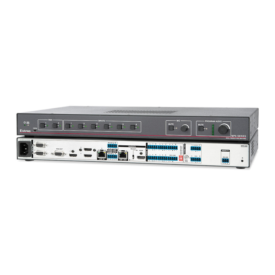
The MPS 602 is housed in a 1U, full rack width rack- or desk-mountable metal enclosure. The switcher can also be surface-mounted under a table, desk, or podium, or on a wall (see Mounting the Switcher on page 33 for additional mounting details). Rear Panel Connections MPS 602 SA 100-240V 1.0A MAX RS-232 VARIABLE... -
Page 12: Dtp Input And Output
DTP Input and Output DTP In — Connect a DTP 230 source (Tx) to this RJ-45 jack (numbered 6 on the rear panel). The DTP input includes the HDMI (or DVI with the proper adapter) video with embedded audio, bi-directional RS-232 and IR, separate balanced or unbalanced analog audio, and remote power for a connected DTP Tx device. - Page 13 Mic/Line input — One 3-pole captive screw connector switchable between mic and line level inputs. Wire the connector as shown below (see figure 4). Use the configuration software to select the mic or line input level. " (5 mm) MAX. (typ) Ring Sleeve Sleeve Jumper...
-
Page 14: Program Audio Output
NOTE: The variable audio output level is controlled by the front panel volume encoder. Mic Mix — One potentiometer controls the mic/line input level ( ) mixed into the fixed MPS 602 SA RS-232 VARIABLE OUTPUTS audio output (... -
Page 15: Control Ports
Control ports RS-232 remote — A 3-pole, 3.5 mm captive screw connector for connection of a host computer or a controller using SIS or Windows-based control software. RS-232 Device Bidirectional Transmit (Tx) Transmit (Tx) Do not tin Receive (Rx) Receive (Rx) the wires! Ground ( Ground (... -
Page 16: Lockit Lacing Bracket
LockIt Lacing Bracket LockIt lacing brackets are provided to secure the HDMI cables to the rear panel connectors as shown. The configuration of the HDMI connectors on the MPS 602 rear panel require using a top mount (HDMI input 3) and a single or stacked side mount (HDMI inputs 4 and 5) installation to secure the three inputs. -
Page 17: Cabling The Mps 602 Switcher
The MPS switcher can be connected to as many as six input devices. It can output to one of two outputs (HDMI or DTP). Follow the steps below and the installation example (see the MPS 602 Application Diagram on page 11) Turn off power to the MPS switcher and all devices that will be connected to it. -
Page 18: Operation
Operation This section discusses how to connect, configure, and operate the MPS 602. Topics that are covered include: • Front Panel Operation • HDMI/DTP Embedded Audio Output • Program Audio • EDID Minder HDCP • Front Panel Operation PROGRAM AUDIO INPUTS MUTE MUTE EXEC... -
Page 19: Input Auto Switch
HDMI (digital output group) — HDMI input buttons 3, 4, and 5 select the input for the HDMI or DTP output and the corresponding audio switcher section. The LEDs to the right of each button (when lit) indicate the selected input. DTP Input (digital output group)—... -
Page 20: Front Panel Security Lockout (Executive Mode)
Program Audio Control — This rotary encoder increases or decreases the variable program audio output (see figure on page 5, ) and the amplified audio output (MPS 602 MA and MPS 602 SA only, see figure on page 5, ) with this volume encoder knob. -
Page 21: Hdmi/Dtp Embedded Audio Output
HDMI/DTP Embedded Audio Output By default, the original embedded audio present on the selected HDMI or DTP input is routed to the selected HDMI or DTP audio output. If an RGB input is selected there will be no audio output. Optionally, program audio can be routed to the embedded output instead (see Audio Routing on page 29). -
Page 22: Mic Mix Control
Mic Mix Control The Mic mix knob simultaneously adjusts the mic volume mixed into the program audio output and into the amplified audio output. It has no effect on the fixed audio output. Rotate clockwise to increase mic volume and counterclockwise to decrease. Program Audio Volume Use the front panel rotary encoder knob to increase or decrease PROGRAM AUDIO... -
Page 23: Audio Gain And Attenuation Adjustments
Audio Gain and Attenuation Adjustments Front Panel LEDs Each audio input level (analog inputs 1 through 5 only) is adjusted from the front panel over a range of -18 dB to +24 dB. The adjustments normalize the input audio levels so that output volume is consistent for all inputs. The front panel input indicator LEDs provide a status of the current input gain or attenuation level. -
Page 24: Microphone Controls
Microphone Controls Mic Mute and Volume Mic volume and mute are controlled from the front panel. The mic mute button toggles the mic input on or off. The corresponding red LED lights when mic volume is disabled (muted). When the mic input is unmuted (enabled), it is mixed with the program audio output at a level set by the mic volume rotary encoder. -
Page 25: Edid Minder
EDID Minder The digital and analog groups feature EDID Minder, ensuring that each input source reads the EDID of the output display even when the input is not selected. The result is the video source powers up properly and reliably outputs content when selected. The EDID remains in the selected mode (automatic or user assigned) even after loss of power. -
Page 26: User Assigned Edid Mode
User assigned EDID Mode Using SIS commands, an EDID file can be selected from a table of 56 EDID files. Six additional EDID file locations are reserved for user-loaded EDID files for the RGB and HDMI/DVI/DTP inputs. Once a user assigned EDID is selected, it is stored at that input and EDID polling ceases for a connected display. -
Page 27: Hdcp
Native Video Variable Refresh Rate Type Audio Resolution Format 800 x 600 60 Hz HDMI 2-Ch 1024 x 768 60 Hz HDMI 2-Ch 1280 x 768 60 Hz HDMI 2-Ch 1280 x 800 60 Hz HDMI 2-Ch 1280 x 1024 60 Hz HDMI 2-Ch... -
Page 28: Remote Communication And Control
Remote Communication and Control This section discusses SIS programming and control of the MPS 602 including: • Connection Options • Host-to-MPS Communications • Command and Response Table Connection Options The MPS 602 can be remotely connected via a host computer or other device (such as a control system) attached to the rear panel RS-232 port or the front panel USB Config port. -
Page 29: Front Panel Configuration Port
MODE CONFIG MPS SERIES MEDIA PRESENTATION SWITCHER MPS 602 Front Panel Figure 16. Connecting a PC to the MPS 602 Front Panel USB Port If this is the first time an Extron product is connected to the PC, the Found New dialog opens. -
Page 30: Host-To-Mps Communications
The MPS 602-initiated messages are listed below (underlined). Boot-up messages (c) Copyright 20 nn, Extron Electronics, MPS 602, Vx.xx The copyright message is initiated by the switcher when it is first powered on and connected using the RS-232 serial connector. -
Page 31: Mps Switcher Error Responses
MPS Switcher Error Responses When the MPS switcher receives an SIS command and determines that it is valid, it performs the command and sends a response to the host device. If the switcher is unable to perform the command because the command is invalid or contains invalid parameters, it returns an error response to the host. - Page 32 = Input select 0 through 6 (0 = deselect) = Program audio ducking level in talk-over mode in dB (0 to 30,0 = off) = Audio input gain/attenuation in dB (-18 to +24, in 1 dB steps) = Audio input gain in dB (0 to 24, in 1 dB steps) = Audio input attenuation in dB (1 to 18, in 1 dB steps) User assigned EDID Mode = EDID slot number from lookup table (see...
- Page 33 Command/response table for SIS commands Command ASCII Command Response Description (host to switcher) (switcher to host) Input selection Select video and audio input X1! • Select input audio and video. X1! ] View current input View active input X1! • Select video input only Select input video only.
- Page 34 Command ASCII Command Response Description (host to switcher) (switcher to host) Picture Adjustments (RGB Inputs only) Set pixel phase EX1! X3) ] PHAS Phas Set pixel phase of input Increment pixel phase value EX1! X3) ] PHAS Phas Increase input pixel phase to EX1! X3) ]...
- Page 35 Command ASCII Command Response Description (host to switcher) (switcher to host) Audio Routing Set input audio format X2@ ] AFMT AfmtI HDMI inputs 3 through 6 only View input audio format X2@ ] AFMT View audio format of input Set output HDMI/DTP audio X! ] AFMT AfmtO...
- Page 36 Command ASCII Command Response Description (host to switcher) (switcher to host) Mic level Specify gain X^ ] variable is a positive number. Specify attenuation X^ ] variable is a positive number. View mic level X^ ] 16G/g = overall mic gain or attenuation between -18 dB and +60 dB.
- Page 37 Command ASCII Command Response Description (host to switcher) (switcher to host) HDCP Management Set HDCP authorization per X# ] HDCP HdcpE HDMI/DTP inputs 3-6 only input Set HDCP authorization all X# ] HDCP HdcpE = 0=disabled/off inputs 1=enabled/on (default) X# ] View HDCP status EHDCP HdcpE...
- Page 38 Command ASCII Command Response Description (host to switcher) (switcher to host) Setup/Naming commands E X1( • X1( ] Set the unit name E • Return the unit name to default MPS-602 • • X1( ] View unit name Request part number Request part number 60-xxxx-xx MPS602=60-1313-01...
-
Page 39: Reference Information
Reference Information This section contains information about mounting options, DataViewer, and firmware updates for the MPS 602. Topics that are covered, include: • Mounting the Switcher • DataViewer • Updating Firmware Mounting the Switcher The MPS 602 is housed in 1U tall, full rack width, 8.5 inches deep metal enclosure, rack- or desk-mountable. -
Page 40: Ul Rack Mounting Guidelines
UL Rack Mounting Guidelines The following Underwriters Laboratories (UL) guidelines pertain to the safe installation of the MPS 602 in a rack. Elevated operating ambient temperature — If installed in a closed or multi-unit rack assembly, the operating ambient temperature of the rack environment may be greater than room ambient temperature. -
Page 41: Dataviewer
DataViewer DataViewer is an enhanced terminal emulation program that facilitates analysis of RS-232, USB, and TCP/IP communication with Extron devices. The software allows users to send commands to a device and view the responses in ASCII or hexadecimal format. Command and response logs can be saved in text or HTML format. -
Page 42: Updating Firmware
Visit the Extron Web site, www.extron.com. From the Product page, locate and select the MPS 602 (in the left column select Switchers > Media Presentation Switchers > MPS 602 On the MPS 602 product page, click the Downloads tab and locate the most recent firmware file, release notes, and firmware update instructions. - Page 43 Locate the previously downloaded firmware file and click once to select it. The main screen reopens. Click the box under to select the firmware file. Devices(1) Click to start the upgrade. The total progress bar tracks the loading progress. Begin When the message appears, the upload is finished.
-
Page 44: Extron Warranty
Extron Electronics makes no further warranties either expressed or implied with respect to the product and its quality, performance, merchantability, or fitness for any particular use. In no event will Extron Electronics be liable for direct, indirect, or consequential damages resulting from any defect in this product even if Extron Electronics has been advised of such damage.
Need help?
Do you have a question about the MPS 602 and is the answer not in the manual?
Questions and answers