Table of Contents
Advertisement
Quick Links
Advertisement
Table of Contents

Related Manuals for Extron electronics MTPX Plus Series


Summary of Contents for Extron electronics MTPX Plus Series
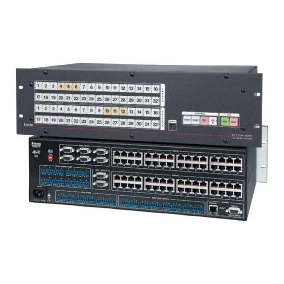
- Page 1 MTPX Plus Series Mini Twisted Pair Matrix Switcher 68-1383-01 Rev. B 09 08...
- Page 2 Precautions Safety Instructions • English This symbol is intended to alert the user of important operating and maintenance (servicing) instructions in the literature provided with the equipment. This symbol is intended to alert the user of the presence of uninsulated dangerous voltage within the product’s enclosure that may present a risk of electric shock.
- Page 3 FCC Class A Notice This equipment has been tested and found to comply with the limits for a Class A digital device, pursuant to part 15 of the FCC Rules. Operation is subject to the following two conditions: (1) this device may not cause harmful interference, and (2) this device must accept any interference received, including interference that may cause undesired operation.
-
Page 5: Table Of Contents
Table of Contents Chapter One • Introduction About this Manual ... 1-2 About the MTPX Plus Twisted Pair Matrix Switchers Twisted pair (TP) cable advantages Transmission distances ... 1-4 Skew equalization ... 1-7 Definitions ... 1-7 Features ... 1-8 Chapter Two • Installation Mounting the Switcher UL guidelines ... - Page 6 Table of Contents, cont’d Using presets ... 3-28 Example 6: Saving a preset ... 3-29 Example 7: Recalling a preset ... 3-30 Muting and unmuting audio/RS-232 outputs Example 8: Muting and unmuting an audio/RS-232 output ... 3-32 Viewing and adjusting the TP input audio level Example 9: Viewing and adjusting an input audio level ...
- Page 7 Using the Command/Response Tables Command/Response Table for SIS Commands Symbol definitions ... 4-8 Command/response table for SIS commands Command/Response Table for IP-specific SIS Commands Symbol definitions ... 4-23 Command/response table for IP-specific SIS commands Special Characters ... 4-26 Chapter Five • Matrix Software Matrix Switchers Control Program Installing the software Software operation via Ethernet...
- Page 8 Table of Contents, cont’d Special Characters ... 5-27 Button-Label Generator Program Using the Button-Label Generator software Chapter Six • HTML Operation Download the Startup Page System Status Page ... 6-3 System Settings Page IP Settings fields ... 6-4 Unit Name field ... 6-4 DHCP radio buttons ...
- Page 9 Appendix A • Ethernet Connection Ethernet Link ... A-2 Ethernet connection ... A-2 Default address ... A-2 Pinging to determine the Extron IP address ... A-3 Pinging to determine the Web IP address ... A-3 Connecting as a Telnet client Telnet tips ...
- Page 10 Table of Contents, cont’d 68-1383-01 B 09 08 All trademarks mentioned in this manual are the properties of their respective owners. MTPX Plus Twisted Pair Matrix Switchers • Table of Contents...
-
Page 11: Chapter One • Introduction
MTPX Plus Twisted Pair Matrix Switchers Chapter One Introduction About this Manual About the MTPX Plus Twisted Pair Matrix Switchers Definitions Features... - Page 12 Introduction About this Manual This manual contains installation, configuration, and operating information for the Extron MTPX Plus Twisted Pair (TP) Matrix Switchers. About the MTPX Plus Twisted Pair Matrix Switchers The MTPX Plus matrix switcher distributes signals that are compatible with the Extron MTP and VTT/VTR product lines.
- Page 13 The MTPX Plus switcher has a minimum bandwidth of 300 MHz (-3 dB). The switchers can also switch RGBS, RGsB, RsGsBs, HDTV, component video, S-video, and composite video. MTPX Plus Twisted Pair Matrix Switchers • Introduction...
-
Page 14: Twisted Pair (Tp) Cable Advantages
(15 m) from the switcher when the Pre-Peak feature is on. For daisy-chained units, any receiver in the chain closer than 350’ (105 m) may experience some form of over-peaking when the Pre-Peak switch is on. An overpeaked image may appear bloomed. - Page 15 Recommended maximum TP transmission distances at 60 Hz, — MTP transmitter to switcher when the display is on the MTPX Plus local (VGA) output MTP Transmitter IT OR M ON W ER LOCAL INPUTS INPUT SELECT LOCAL RJ-45 RS-232 OUTPUT INSERTION LOCAL OUTPUTS Tx Rx Tx Rx...
- Page 16 Introduction, cont’d Recommended maximum TP transmission distances at 60 Hz, — transmitter to receiver using MTPX TP inputs and outputs MTP Transmitter IT OR M ON W ER Tx Rx Tx Rx 3.2A MAX Video format Component, S-video Composite 640 x 480 800 x 600 1024 x 768* 1280 x 960*...
-
Page 17: Skew Equalization
Skew equalization Skew exists between wire pairs when the physical length of one wire pair is different from another. Skew affects the displayed image when the differential length between wire pairs exceeds 2 feet, causing the timing of the red, green, and blue video signals to appear out of alignment (horizontal registration errors). -
Page 18: Features
Introduction, cont’d Features Twisted pair inputs and outputs — The switchers input and output TP signals on female RJ-45 connectors. N For low resolution MTPs (S-video and composite video) on the TP inputs, the MTPX Plus audio circuits are compatible only with the newer generation, mono audio models. - Page 19 Operational flexibility — Operations such as input/output selection, setting of presets, and adjustment of audio levels can be performed on the front panel or via either serial port. The serial ports allow remote control via a PC or a control system. •...
- Page 20 Introduction, cont’d 1-10 MTPX Plus Twisted Pair Matrix Switchers • Introduction...
-
Page 21: Chapter Two • Installation
MTPX Plus Twisted Pair Matrix Switchers Chapter Two Installation Mounting the Switcher Rear Panel Cabling and Settings Front Panel Configuration Port... -
Page 22: Ul Guidelines
Installation Mounting the Switcher UL guidelines The following Underwriters Laboratories (UL) guidelines pertain to the installation of the MTPX Plus into a rack. Elevated operating ambient temperature — If the equipment is installed in a closed or multi-unit rack assembly, the operating ambient temperature of the rack environment may be greater than room ambient temperature. -
Page 23: Rear Panel Cabling And Settings
Rear Panel Cabling and Settings Figure 2-2 shows the rear panel of the MTPX Plus 1616. LOCAL OUTPUT LOCAL INPUTS LISTED 1T23 I.T.E. AUDIO 1.6A MAX MONO AUDIO OUTPUTS Figure 2-2 — MTPX Plus 1616 twisted pair matrix switcher N The MTPX Plus 816 and MTPX Plus 168 are housed in the same 2U enclosure, but have fewer input and/or output connectors to accommodate their smaller matrix sizes. -
Page 24: Signal Inputs
Installation, cont’d Signal inputs Inputs (TP) connectors — Connect the TP outputs of compatible MTP or VTT transmitters to these RJ-45 female connectors. N • • • • Figure 2-4 shows the recommended termination of TP cables in accordance with the TIA/EIA T568A or TIA/EIA T568B wiring standards. You can use either standard with CAT 5, 5e, or 6 cable, but use the same standard on both ends of the cable. - Page 25 MTP output or input be connected by a minimum of 50' (15 m) of TP cable to prevent o verpeaking. The matrix switchers can also input and switch HD component video, • component video, S-video, or composite video by using the appropriate adapters.
-
Page 26: Rs-232 Output Inserts
(when enabled as described in the note above), RS-232 Output Insert 2 is routed to the Output 2 TP connector, and so on. The switch time for the RS-232 output insert is 50 ms. Do not connect this device to a computer data or telecommunications network , in the “Signal inputs”... - Page 27 N • Matrix sizes 1616 and smaller have one local video output. Matrix sizes 1632 and larger have two local video outputs. These outputs are always outputs 1 and 2, with the same inputs tied to them • as to TP outputs 1 and 2. •...
-
Page 28: Rs-232/Rs-422 Connection
Installation, cont’d By default, the audio ties follow the video ties. Audio breakaway, which can be activated via the front panel or under serial port or Ethernet control, allows you to select from any one of the audio input sources and route it separately from its corresponding video source. -
Page 29: Cabling
Cabling It is vital that your Ethernet cables be the correct cable type, and that they be properly terminated with the correct pinout. Ethernet links use Category (CAT) 5e or CAT 6, unshielded twisted pair (UTP) or shielded twisted pair (STP) cables, terminated with RJ-45 connectors. -
Page 30: Reset Button
Installation, cont’d Side Figure 2-10 — RJ-45 connector and pinout tables Reset button Reset button — The Reset button initiates two levels of reset to the matrix switcher. For two different reset levels, press and hold the button while the switcher is running or while you power up the switcher. See “Rear Panel Operations”... -
Page 31: Front Panel Configuration Port
ENTER PRESET VIEW CONFIG MTPX PLUS SERIES SWITCHER Figure 2-11 — Front panel configuration port Configuration port — This 2.5 mm mini stereo jack serves the same serial communications function as the rear panel Remote port, but it is easier to access than the rear port after the matrix switcher has been installed and cabled. - Page 32 Installation, cont’d 2-12 MTPX Plus Twisted Pair Matrix Switchers • Installation...
-
Page 33: Chapter Three • Operation
MTPX Plus Twisted Pair Matrix Switchers Chapter Three Operation Front Panel Controls and Indicators Front Panel Operations Rear Panel Operations Optimizing the Audio Video Adjustments Troubleshooting Configuration Worksheets... - Page 34 , are grouped on the left side of the control INPUTS CONTROL ENTER PRESET CONFIG OUTPUTS ENTER PRESET CONFIG , are AUDIO VIEW VIDEO MTPX PLUS SERIES MTP MATRIX SWITCHER CONTROL VIEW VIDEO AUDIO MTPX PLUS SERIES MTP MATRIX SWITCHER...
-
Page 35: Input And Output Buttons
Input and output buttons Primary functions Action: Indications: Secondary functions I/O Grouping Action 1: Input 1 and Output 1: Select I/O Group mode. Action 2/ indication: Presets Action/ indication: Input audio Action/ level indication: (inputs) Indication (outputs) Output audio Action/ volume indication: (outputs) - Page 36 Operation, cont’d N If the switcher has fewer inputs or outputs than input or output buttons, only the buttons for which the switcher has an input or output select and identify that input or output. Input buttons — The input buttons have two primary functions (•) and six secondary functions (❏): •...
-
Page 37: Control Buttons
Control buttons Primary functions Action: Save changes Indication: Blink: save needed ENTER Secondary functions I/O Grouping Action/ Select group 1. indication: Port and input Action 1: configuration Action 2/ Select 9600 baud. indication: Blink: selected Front panel Action: With Video and locks Audio, select Lock mode 2 and/or... - Page 38 Operation, cont’d Preset button — The Preset button has two primary functions (•) and three secondary functions (❏): • Activates Save Preset mode to save a configuration as a preset and Recall Preset mode to activate a previously-defined preset. • Blinks when Save Preset mode is active and lights steadily when Recall Preset mode is active.
- Page 39 Esc ( > ) button — The Esc ( > ) button has two primary functions (•) and five secondary functions (❏): • Cancels operations or selections in progress and resets the front panel button indicators. N The Esc ( >...
-
Page 40: I/O Controls
Operation, cont’d I/O controls Primary functions Secondary functions Front panel locks Resets Port configuration Audio Video button — The Video button has two primary functions (•) and four secondary functions (❏): • Selects and deselects video for a configuration that is being created or viewed. -
Page 41: Button Icons
Audio button — The Audio button has two primary functions (•) and five secondary functions (❏): • Selects and deselects audio (or RS-232 if the audio/RS-232 wire pair is set for RS-232) for a configuration that is being created or viewed. •... -
Page 42: Front Panel Operations
Operation, cont’d Front Panel Operations The following sections detail the power-up process and then provide sample procedures for the following actions: • Creating ties, sets of ties, and configurations • Changing a configuration • Viewing ties, sets of ties, and configurations •... -
Page 43: Front Panel Security Lockouts
Front panel security lockouts In the procedural descriptions that follow, it is assumed that the switcher is in Lock mode 0 (fully unlocked). The following two Lock modes are also available: • Lock mode 1 — All changes are locked from the front panel (except for setting Lock mode 2). -
Page 44: Creating A Configuration
Operation, cont’d Creating a configuration The current configuration can be changed using the front panel buttons. Change the current configuration as follows: Press the Esc button to clear any input button indicators, output button indicators, or control button indicators that may be lit. Select video, audio, or both for configuration by pressing the Video button and/or Audio button. -
Page 45: Example 1: Creating A Set Of Video And Audio Ties
Example 1: Creating a set of video and audio ties In the following example, input 5 is tied to outputs 3, 4, and 8. The steps show the front panel indications that result from your action. N This example assumes that there are no ties in the current configuration. Press and release the Esc button (figure 3-4). - Page 46 Operation, cont’d N You can cancel the entire set of ties at this point by pressing and releasing the Esc button. The Esc button flashes once. Press and release the Enter button (figure 3-8). Press the Enter button to confirm the configuration change.
-
Page 47: Example 2: Adding A Tie To A Set Of Video And Audio Ties
Example 2: Adding a tie to a set of video and audio ties In the following example, a new video tie is added to the current configuration. The steps show the front panel indications that result from your action. N This example assumes that you have performed example 1. Press and release the Esc button (figure 3-10). - Page 48 Operation, cont’d Press and release the Enter button (figure 3-14). Press the Enter button to confirm the configuration change. ENTER The Enter button returns to unlit or background illumination. Figure 3-14 — Press the Enter button The current configuration (figure 3-15) is now: •...
-
Page 49: Example 3: Removing A Tie From A Set Of Video And Audio Ties
Example 3: Removing a tie from a set of video and audio ties In the following example, an existing audio tie is removed from the current configuration. The steps show the front panel indications that result from your action. N This example assumes that you have performed example 1 and example 2. Press and release the Esc button (figure 3-16). - Page 50 Operation, cont’d Press and release the output 4 button (figure 3-19). Press and release the Output 4 button. The button blinks red to indicate the pending change: audio input will be untied. 17 18 19 20 21 22 23 24 31 32 Figure 3-19 —...
-
Page 51: Viewing A Configuration
Viewing a configuration The current configuration can be viewed using the front panel buttons. The View-only mode prevents inadvertent changes to the current configuration. View-only mode also provides a way to mute audio or RS-232 outputs (see “Muting and unmuting audio/RS-232 outputs” on page 3-32. View the current configuration as follows: Press the Esc button to clear any input button indications, output button indications, or control button indications that may be on. -
Page 52: Example 4: Viewing Video And Audio (Rs-232), Audio (Rs-232) Only, And Video Only Ties
Operation, cont’d Example 4: Viewing video and audio (RS-232), audio (RS-232) only, and video only ties In the following example, we view the video and audio (or RS-232), audio- (or RS-232-) only, and video-only ties in the current configuration. The steps show the front panel indications that result from your action. - Page 53 Press and release the input 5 button (figure 3-24). Press and release the Input 5 button. The button lights amber. 17 18 19 20 21 22 23 24 32 Green Amber Green 17 18 19 20 21 22 23 24 32 The output buttons for outputs that are not tied to Input 5 are either unlit or background illuminated.
- Page 54 Operation, cont’d Press and release the Video button and the Audio button to toggle the Video button on green and the Audio button either unlit or background illuminated (figure 3-26). Press the Video button to select it. The button lights green when selected.
-
Page 55: I/O Grouping
I/O grouping I/O grouping is a matrix switcher feature that allows you to subdivide the front panel controls of the matrix into four smaller functional sub-switchers and limit tie creation using the front panel only. Inputs and outputs can be assigned to one of four groups or not assigned to any group. - Page 56 Operation, cont’d The I/O groups can be set up on the front panel or by using RS-232/RS-422 and LAN ports and either the SIS or the Windows control program (see chapter 4, “Programmer’s Guide”, and chapter 5, “Matrix Software”). Create I/O groups on the front panel as follows: N I/O groups are protected when front panel lock mode 2 is selected.
-
Page 57: Example 5: Grouping Inputs And Outputs
Example 5: Grouping inputs and outputs In the following an example, several switcher inputs and outputs are assigned to groups. The steps show the front panel indications that result from your action. Press and release the Esc button (figure 3-29). Press the Esc button to clear all selections. - Page 58 Operation, cont’d Press and release the Input 1 through 4 and Output 1 through 4 buttons (figure 3-32). Press and release the Input 1 through Input 4 buttons. The selected buttons light green. 17 18 19 20 21 22 23 24 31 32 Press and release the Output 1 through Output 4 buttons.
- Page 59 Simultaneously press and release the Video button and Audio button (figure 3-35). The switcher exits I/O Group mode. N If you do nothing for approximately 30 seconds, the front panel times out and the switcher exits I/O Group mode. • Group 1 consists of inputs 1 through 4 and outputs 1 through 4.
-
Page 60: Using Presets
Operation, cont’d Using presets The current configuration (configuration 0) can be saved as a preset in any one of 32 preset memory addresses. All 32 presets are assigned to the input buttons and output buttons and are available to be either saved or retrieved from the front panel. -
Page 61: Example 6: Saving A Preset
Example 6: Saving a preset In the following example, the current configuration is saved as a preset. The steps show the front panel indications that result from your action. Press and release the Esc button (figure 3-37). Press the Esc button to clear all selections. C O N T R O L VIEW ENTER... -
Page 62: Example 7: Recalling A Preset
Operation, cont’d Press and release the Enter button (figure 3-40). The current configuration is now stored in the selected memory location. Press the Enter button to save the preset. ENTER PRESET The Enter and Preset buttons return to unlit or background illumination. - Page 63 Press and release the input or output button for the desired preset (figure 3-43). Press and release the Input 1 button. The button blinks red to indicate that this preset number is selected but not recalled. 4 15 16 17 18 19 20 31 32 Figure 3-43 —...
-
Page 64: Muting And Unmuting Audio/Rs-232 Outputs
Operation, cont’d Muting and unmuting audio/RS-232 outputs Individual audio or RS-232 outputs can be muted or unmuted as follows: N Mutes are protected when front panel Lock mode 2 is selected. You can view the status of the output (muted or unmuted) in Lock mode 2 but you cannot change it from the front panel. - Page 65 Video cannot be I / O muted. The lit status of the button VIDEO AUDIO is unimportant. Until you select an input, the buttons for all outputs with no audio ties light amber if no inputs are tied or red if only video is tied. Red Amber Unlit 17 18 19 20 21 22 23 24 31 32 Figure 3-46 —...
-
Page 66: Viewing And Adjusting The Tp Input Audio Level
1 2 3 4 5 6 7 8 9 10 11 12 13 14 15 16 ENTER PRESET VIEW VIDEO AUDIO CONFIG OUTPUTS MTPX PLUS SERIES MTP MATRIX SWITCHER MTPX Plus 1616 No noticeable volume differences between sources CD Jukebox Output... -
Page 67: Example 9: Viewing And Adjusting An Input Audio Level
Audio gain and attenuation is displayed differently on different models. • Switchers with 32 output buttons — Each output button indicates 1 dB when lit steadily. See the table on page 3-36. • Switchers with 16 output buttons — Each output button indicates 1 dB when blinking and 2 dB when lit steadily. - Page 68 Operation, cont’d 32-output button audio gain and attenuation display MTPX Plus 1632, 3216, 3232 HVA 9 10 11 12 13 14 15 16 18 19 20 21 22 23 24 25 26 27 28 29 30 31 32 9 10 11 12 13 14 15 16 18 19 20 21 22 23 24 25 26 27 28 29 30 31 32 9 10 11 12 13 14 15 16 18 19 20 21 22 23 24 25 26 27 28 29 30 31 32...
- Page 69 16-output button audio gain and attenuation display 816, 168, 1616 = Unlit button = Blinking button Green indicates a positive (gain) level. Red indicates a negative (attenuation) level. MTPX Plus Twisted Pair Matrix Switchers • Operation MTPX Plus 9 10 13 14 15 16 9 10...
- Page 70 Operation, cont’d Press and release the Input 5 button (figure 3-53). 17 18 19 20 21 22 23 24 31 32 The output buttons display the selected input’s audio level and polarity (gain or attenuation). • Each output button indicates 1 dB when lit. When the buttons are lit green, they indicate a gain (+) audio level.
- Page 71 Press the View button to decrease the input audio level by 1 dB per button push. VIEW Unlit 8 15 16 17 18 19 20 21 22 23 24 31 32 Unlit Figure 3-55 — Adjust the input audio level Figure 3-56 shows the same level (–1 dB) as in figure 3-55, but displayed on a 16-output-button switcher, such as a MTPX Plus 1616.
-
Page 72: Viewing And Adjusting The Local Output Volume
Operation, cont’d Viewing and adjusting the local output volume The audio level of each local output can be displayed and adjusted through a range of 100% (no attenuation) to 0% (maximum [76 dB] attenuation). The audio level can be adjusted from the front panel or under RS-232/RS-422 or Ethernet control. The default volume is 100% (no attenuation). - Page 73 Audio volume display Highest # input button lit 16-input 32-input dB of Output switcher switcher attenuation volume None None 5.5% 8.5% 11.5% 14.5% 17.5% 20.5% 23.5% 26.5% 29.5% 32.5% 35.5% 38.5% 41.5% 44.5% 47.5% 50.5% MTPX Plus Twisted Pair Matrix Switchers • Operation Highest # input button lit 16-input...
- Page 74 Operation, cont’d Depending on the switcher model, the input buttons blink or light sequentially to indicate the approximate volume of the selected output. Volume is defined as a percentage of the input audio signal that is applied to the output. From 0% of volume, the first Esc ( 5.5% on, each Esc ( •...
-
Page 75: Example 10: Viewing And Adjusting A Local Output Volume Level
Example 10: Viewing and adjusting a local output volume level In the following example, the audio output volume is viewed and adjusted. The steps show the front panel indications that result from your action. N Because of the different volume display schemes, the output volume levels that result from the following example are shown twice: as displayed on a 32-input button switcher and on a 16-input button switcher. - Page 76 Operation, cont’d Figure 3-61 shows the same volume (41.5%) as in figure 3-61, but displayed on a 16-input-button switcher, such as an MTPX Plus 1616. • The input LEDs display the selected output's audio volume level. • In this example, the lit/blinking input buttons indicate 41.5 to 44.5 percent of the applied audio input. •...
- Page 77 Figure 3-63 shows the same volume (61%) as in figure 3-62, but displayed on a 16-input-button switcher, such as an MTPX Plus 168. Lit Buttons • The input LEDs display the selected output’s audio volume level. • In this example, the lit/blinking input buttons indicate 59.5 to 62.5 percent of the applied audio input. •...
-
Page 78: Setting The Front Panel Locks (Executive Modes)
Operation, cont’d Setting the front panel locks (Executive modes) The matrix switcher has three levels of front panel security lock that limit the operation of the switcher from the front panel. The three levels are: • Lock mode 0 — The front panel is completely unlocked. All front panel functions are available. -
Page 79: Selecting Lock Mode 2 Or Toggling Between Mode 2 And Mode 0
Selecting Lock mode 2 or toggling between mode 2 and mode 0 N If the switcher is in Lock mode 0 or mode 1, this procedure selects mode 2. If the switcher is in Lock mode 2, this procedure selects mode 0 (unlocks the switcher). -
Page 80: Performing A System Reset From The Front Panel
Operation, cont’d Performing a system reset from the front panel The front panel reset is identical to issuing the (see chapter 4, “Programmer’s Guide”). A system reset performs the following functions: • Clears all ties and presets • Clears all audio or RS-232 mutes •... -
Page 81: Defining The Audio/Rs-232 Wire Pair
Press and hold the Input 1 and Input 2 buttons simultaneously to toggle background illumination mode on or off. 3 16 17 18 19 32 After approximately 2 seconds, release the Input 1 and Input 2 buttons. Figure 3-68 — Toggle background illumination on or off Defining the audio/RS-232 wire pair N The TP audio/RS-232 input wire pair configurations are protected when front panel Lock mode 2 is selected. -
Page 82: Selecting The Rear Panel Remote Port Protocol And Baud Rate
Operation, cont’d To change an input’s audio/RS-232 wire pair configuration, press and release the input button to toggle that input’s configuration (figure 3-70). Press and release the Input 8 button to toggle the configuration of input 8’s audio/RS-232 wire pair (to audio, in this example). Figure 3-70 —... -
Page 83: Rear Panel Operations
Release the Control buttons. N If front panel Lock mode 2 is selected and you try to perform step 3, the actions are ignored and the Enter, Video, and Audio buttons flash. See “Setting the front panel Locks (Executive modes)” on page 3-46. To change a value, press and release the button that relates to the desired value (figure 3-73). - Page 84 Operation, cont’d Mode Activation Hold down the recessed Reset button while applying power to the switcher. N After a mode 1 reset is performed, update the switcher’s firmware to the latest version. Do not operate the switcher firmware version that results from the mode 1 reset.
-
Page 85: Performing A Hard Reset (Reset 1)
Performing a hard reset (reset 1) The hard reset function restores the switcher to the base firmware that it was shipped with. After a hard reset, events do not automatically start, but user settings and files are restored. Perform a hard reset as follows: N The hard reset restores the factory-installed firmware. -
Page 86: Performing Soft System Resets (Resets 3, 4, And 5)
Operation, cont’d Performing soft system resets (resets 3, 4, and 5) Perform a soft reset of the switcher as follows: Use an Extron Tweeker or other small screwdriver to press and hold the rear panel Reset button until the front panel Video and Audio buttons blink the number of times for the desired reset: once (events reset), twice (system reset), or three times (absolute reset) (figure 3-76). -
Page 87: Optimizing The Audio
Power on the audio sources, the switcher, and the audio players. Switch among the inputs (see “Creating a configuration”, in this chapter), listening to the audio with a critical ear or measuring the output audio level with test equipment, such as a VU meter. -
Page 88: Configuration Worksheets
Operation, cont’d Configuration Worksheets Rather than trying to remember the configuration for each preset, use worksheets to record this information. Make copies of the blank worksheet on page 3-59 (32-input button and -output button switchers) and page 3-61 (16-button switchers) and use one for each preset configuration. -
Page 89: Worksheet Example 2: Daily Configuration
Worksheet example 2: Daily configuration Figure 3-78 continues from worksheet example 1 by showing the video and audio ties that make up the configuration of preset 1. Solid lines shows video ties and dashed lines show the audio ties. Camera/ Camera PC 1 PC 2... -
Page 90: Worksheet Example 3: Test Configuration
Operation, cont’d Worksheet example 3: Test configuration The A/V system in our fictional organization needs to be fine tuned on a regular basis. Figure 3-79 shows a typical test configuration, with an Extron video test generator (input 12) generating a test pattern to all monitors (outputs 1, 2, 3, and 8). - Page 91 MTPX Plus Twisted Pair Matrix Switchers • Operation 3-59...
- Page 92 Operation, cont’d 3-60 MTPX Plus Twisted Pair Matrix Switchers • Operation...
- Page 93 MTPX Plus Twisted Pair Matrix Switchers • Operation 3-61...
- Page 94 Operation, cont’d 3-62 MTPX Plus Twisted Pair Matrix Switchers • Operation...
-
Page 95: Serial Ports
MTPX Plus Twisted Pair Matrix Switchers Chapter Four Programmer’s Guide Serial Ports Ethernet (LAN) Port Host-to-Switcher Instructions Switcher-Initiated Messages Switcher Error Responses Using the Command/Response Tables Command/Response Table for SIS Commands Command Response Table for IP-specific SIS Commands Special Characters... -
Page 96: Rear Panel Remote Port
Programmer’s Guide Serial Ports The switcher has two serial ports that can be connected to a host device such as a computer running the HyperTerminal utility, an RS-232 capable PDA, or a control system. These ports make serial control of the switcher possible. The serial ports are: •... -
Page 97: Front Panel Configuration Port
Front panel Configuration port N This port is hardwired for RS-232 only. The optional 9-pin D to 2.5 mm mini jack TRS RS-232 cable, part #70-335-01 (figure 4-2) can be used for connection to the Configuration port. 9-pin D Connection Pin 2 Computer's RX line Pin 3... -
Page 98: Ethernet (Lan) Port
Programmer’s Guide, cont’d Ethernet (LAN) Port The rear panel Ethernet connector on the switcher can be connected to an Ethernet LAN or WAN. Communications between the switcher and the controlling device is via telnet (a TCP socket using port 23). The TCP port can be changed if necessary. -
Page 99: Default Ip Addresses
Default IP addresses To access the MTPX Plus switcher via the LAN port, you need the unit’s IP address, and may need the subnet mask and the gateway address. If the IP address has been changed to an address comprised of words and characters, you can determine the actual numeric IP address using the ping (ICMP) utility (see appendix A, “Ethernet Connection”, for more details). -
Page 100: Using Verbose Mode
Programmer’s Guide, cont’d Using Verbose Mode Telnet connections to an MTPX Plus switcher can be used to monitor for changes that occur on the switcher, such as front panel operations and SIS commands from other telnet sockets or a serial port. For a telnet session to receive change notices from the switcher, the telnet session must be in verbose mode 3. -
Page 101: Switcher Error Responses
Innn Audxx The switcher initiates the Aud message when a front panel input audio level change has occurred. nn is the input number and xx is the dB level. Outnn Volxx The switcher initiates the Vol message when a front panel output audio volume change has occurred. -
Page 102: Using The Command/Response Tables
Programmer’s Guide, cont’d Using the Command/Response Tables The command/response tables begin on page 4-10. Lower-case letters are acceptable in the command field except where indicated for the gain and attenuation commands. The table below shows the hexadecimal equivalent of each ASCII character used in the command/response table. - Page 103 N A Room is a subset of operator-selected outputs that relate to each other. The MTPX Plus switchers support up to 10 rooms, each of which can consist of from 1 to 16 outputs. = Group # (for I/O grouping) = Audio or RS-232 mute: = Local input select DIP switch status = Number of inputs X2& = Number of outputs = Part number = Firmware version number to second decimal place (x.xx)
-
Page 104: Command/Response Table For Sis Commands
Programmer’s Guide, cont’d Command/response table for SIS commands Command ASCII command (host to switcher) Create ties • Commands can be entered back-to-back in a string, with no spaces. For example: 1*1!02*02&003*003%4*8$. • The quick multiple tie and tie input to all output commands activate all I/O switches simultaneously. •... - Page 105 3. If the input cable is longer than 300' (90 m), place the MTP signal generator’s Pre-Peak switch on (up when the signal generator‘s RJ-45 connector is to the right as shown at right). If the cable is shorter than 300’ (90 m), place the switch down. = Input number...
- Page 106 Programmer’s Guide, cont’d Command/response table for SIS commands (continued) Command ASCII command (host to switcher) Input skew adjustment Set all input skew adjustment values Example: 2*0*0*4Iseq Increment one input skew adjustment value Example: 2*2*+Iseq Decrement one input skew adjustment value Read input skew Iseq adjustment values...
- Page 107 Command/response table for SIS commands (continued) Command ASCII command (host to switcher) Local video output sync polarity N The command structure differs, depending on the size of the matrix. Matrix sizes 1616 and smaller do not need the local output variable ( ).
- Page 108 Programmer’s Guide, cont’d Command/response table for SIS commands (continued) Command ASCII command (host to switcher) Audio output volume N The table below defines the value of each audio volume step. dB of Output value attenuation volume 5.5% 8.5% 11.5% 14.5% 17.5% 20.5% 23.5%...
- Page 109 Command/response table for SIS commands (continued) Command ASCII command (host to switcher) Audio input gain and attenuation N The set gain (G) and set attenuation (g) commands are case sensitive. X1& Set input audio gain to +dB value Example: 1*2G Set input audio attenuation to -dB value Increment gain...
- Page 110 Programmer’s Guide, cont’d Command/response table for SIS commands (continued) Command ASCII command (host to switcher) Names (continued) EX# , X2! Write input name Example: Podium camNI Read input name EX# , X2! Write output name Example: 1,Main PJ1NO Read output name I/O Grouping N The group that is assigned in each of the following I/O grouping commands ( EX2#...
- Page 111 Command/response table for SIS commands (continued) Command ASCII command (host to switcher) Save, recall, and directly write presets (continued) Direct write process — N The direct write of a global preset should always be preceded by a clear global preset ties command of that same preset number, as shown below.
- Page 112 Programmer’s Guide, cont’d Command/response table for SIS commands (continued) Command ASCII command (host to switcher) Lock (executive) modes N See “Setting the front panel locks (Executive modes)” in chapter 3, “Operation”, for more information on the Lock modes. Lock all front panel functions Lock advanced front panel functions Unlock all front panel...
- Page 113 Command/response table for SIS commands (continued) Command ASCII command (host to switcher) View ties, gain, volume, mutes, presets, and DIP switch status View RGB (video) output tie & Example: 5& View video output tie Example: View audio output tie Example:...
- Page 114 Programmer’s Guide, cont’d Command/response table for SIS commands (continued) Command ASCII command (host to switcher) View ties, gain, volume, mutes, presets, and DIP switch status (continued) EX2) View audio global preset configuration Command description: preset #*starting output # (StO#)*2(=audio)VC Response description: input # (I#) tied to StO#•I# tied to StO#+1•I# tied to StO#+2•...
- Page 115 Command/response table for SIS commands (continued) Command ASCII command (host to switcher) View ties, gain, volume, mutes, presets, and DIP switch status (continued) View Input Select DIP Stat switch positions and level/ peaking status N The response to the View File Directory command differs, depending on whether the command is sent via an RS-232/RS-422 or Telnet connection or sent via a Web browser connection.
- Page 116 Programmer’s Guide, cont’d Command/response table for SIS commands (continued) Command ASCII command (host to switcher) Information requests Information request Request part number N There are up to three separate sets of Extron firmware on which the switcher can report: the controller firmware, which is the overall control firmware;...
-
Page 117: Command/Response Table For Ip-Specific Sis Commands
Command/Response Table for IP-specific SIS Commands Symbol definitions = Matrix name N The following characters are invalid in the name: {space} ~ , @ = ` [ ] { } < > ‘ “ ; : | \ and ?. = Default name = Time and date (for set) = Time and date (for read) - Page 118 Programmer’s Guide, cont’d = Time (in 10 ms increments) to wait for characters X6& = Time (in 10 ms increments) to wait between characters = Port timeout interval (in 10-sec. increments) 4-24 MTPX Plus Twisted Pair Matrix Switchers • Programmer’s Guide 10 (= 100 ms, default) - 32767 2 (= 20 ms, default) - 32767 1 (= 10 seconds) - 65000 (default is 30 = 300 seconds = 5 minutes)
-
Page 119: Command/Response Table For Ip-Specific Sis Commands
Command/response table for IP-specific SIS commands Command ASCII command (host to switcher) IP setup commands EX4) Set matrix name Read matrix name (location Reset matrix name to •CN factory default EX4@ Set time and date Read time and date EX4$ Set GMT offset Example: 8.0CZ... -
Page 120: Special Characters
Programmer’s Guide, cont’d Command/response table for IP-specific SIS commands (continued) Command ASCII command (host to switcher) IP setup commands (continued) , X5! , X5$ , X5# Set e-mail events for recipient Example: EX5! Read e-mail events for recipients EX5^ Set DHCP on or off Read DHCP on/off status EX5&... -
Page 121: Matrix Switchers Control Program
MTPX Plus Twisted Pair Matrix Switchers Chapter Five Matrix Software Matrix Switchers Control Program Optimizing the Video Special Characters Button-Label Generator Program... -
Page 122: Installing The Software
Matrix Software Matrix Switchers Control Program The Windows-based Extron Matrix Switchers Control Program communicates with the switcher via the Ethernet LAN port, the rear panel Remote RS-232/ RS-422 port, and the front panel Configuration (RS-232) port to provides an easy way to set up ties and sets of ties. -
Page 123: Software Operation Via Ethernet
Follow the on-screen instructions. By default, the Windows installation of the Matrix Switchers Control Program creates a C:\Program Files\Extron\ Matrix_Switchers directory, and it places the following four icons into a group folder named “Extron Electronics\Matrix Switchers”: • MATRIX Switcher+ Control Program •... -
Page 124: Using The Matrix Switcher Control Software
Matrix Software, cont’d Using the Matrix Switcher Control software Many items found in the Matrix Switchers Control Program are also accessible via front panel controls (see chapter 3, ”Operation”) and under SIS control (see chapter 4, “Programmer’s Guide”). The Matrix Switcher+ Help Program provides information on settings and on how to use the control program itself. - Page 125 Examine the Matrix IP Address field in the IP Connection window. The field displays the last Matrix IP address entered. If the IP address is correct: Proceed to step 3b. If the address is not correct: Either click in the Matrix IP Address field and enter the IP address or click on the scroll down button ( ) and select from among the recently used addresses.
-
Page 126: Ip Settings/Options Window
Matrix Software, cont’d Figure 5-6 — Sample program window (complete) • To set up audio in Follow mode (audio and video have the same tie configuration), select the Follow box at the bottom of the window (figure 5-5). To set up audio in breakaway mode (audio and video have different tie configurations), deselect the Follow box (figure 5-6). -
Page 127: Matrix Ip Address Field
Figure 5-7 — Control program IP setting/options window N When the control program is connected to the switcher via a serial port, the Administrator and User Password fields are not masked. If a password has been inadvertently changed to an unknown value, you can look up and, if desired, change a password in this window without knowing the current password. -
Page 128: Extron Name/Descriptor Field
Matrix Software, cont’d Extron Name/Descriptor field The Extron Name/Descriptor field contains the name used as the “from” information when the MTPX Plus switcher e-mails notification of its failed or repaired status. This descriptor can be changed to any valid name, up to 12 alphanumeric characters. -
Page 129: Use Dhcp Check Box
Use DHCP check box The Use DHCP check box directs the MTPX Plus switcher to ignore any entered IP addresses and to obtain its IP address from a Dynamic Host Configuration Protocol (DHCP) server (if the network is DHCP capable). Contact the local system administrator. -
Page 130: Mail Server Ip Address Field
Matrix Software, cont’d Mail Server IP Address field The Mail Server IP Address field displays the IP address of the mail server that handles the e-mail for the facility in which the MTPX Plus switcher is installed. Valid IP addresses consist of four 1-, 2-, or 3-digit numeric octets separated by dots (periods). - Page 131 Edit these fields and controls as follows: Click in the desired E-mail Addressee field. The graphic cursor becomes a text cursor. Edit the e-mail address as desired. Standard e-mail address conventions (for example: nnnnn@xxx.com) apply. Press the Tab key on the keyboard or click in another field to exit the e-mail addressee field.
-
Page 132: Updating Firmware
Matrix Software, cont’d Updating firmware The firmware upgrade utility provides a way to replace the firmware that is coded on the switcher’s control board without taking the switcher out of service. Update the switcher firmware as follows: Visit the Extron Web site, www.extron.com, click the Download Center tab, and then click the Firmware link (figure 5-9). - Page 133 Figure 5-10 — Downloading firmware upgrade files MTPX Plus Twisted Pair Matrix Switchers • Matrix Software NOTE This sequence is shown for example only. For the MTPX Plus, the firmware file selected and shown is “MTPX Plus”. Folder where firmware is installed 5-13...
-
Page 134: Ethernet-Connected Firmware Upload
Matrix Software, cont’d Connect a Windows-based computer to either switcher serial port or the switcher LAN port. See chapter 2, “Installation”, for more details. Start the Matrix Switchers Control Program and connect to the matrix switcher. See “Using the Matrix Switcher Control software” in this chapter, steps 1 through 4, starting on page 5-4. -
Page 135: Serial-Port-Connected Firmware Upload
Serial-port-connected firmware upload Figure 5-12 — Firmware loading Click Browse. The open file window appears. Navigate to the folder where you saved the firmware upgrade file. Select the file and click Open. The Firmware Loader returns to the top. Valid firmware files must have the file extension “.S19”. Any other file extension is not a firmware upgrade. - Page 136 Matrix Software, cont’d NOTE This sequence is shown for example only. For the MTPX Plus, the firmware file selected and shown is “MTPX Plus”. Figure 5-13 — Confirm window If necessary, change the port number in the device port field: •...
-
Page 137: Uploading Html Files
Uploading HTML files You can create customized HTML pages for the switcher to display. The HTML Files List window (figure 5-14) provides a way to view the contents of the switcher’s file system and to upload custom HTML pages to the switcher. Figure 5-14 —... -
Page 138: Windows Buttons, Drop Boxes, And Trashcan
Matrix Software, cont’d Windows buttons, drop boxes, and trashcan The buttons, drop boxes, and trash can on the right side of the program window perform the following functions: Power — Unavailable for MTPX Plus Twisted Pair switchers, because the switcher power cannot be controlled via software. Executive Mode —... -
Page 139: Tools Menu
Tools menu Assign device icons — Displays the complete set of input and output device icons. You can drag any of these icons to the input and output boxes. Edit device palette — Allows you to add your own custom device icon graphics. - Page 140 Matrix Software, cont’d MTPX Picture settings — Displays the MTPX Picture Settings window (figure 5-16), which allows you to set the input picture adjustments (level/ peaking and skew) and the output picture adjustments (pre-peaking and skew). The Auto-Calibrate Level/Peaking button lets you use the included MTP signal generator to automatically set the input level/peaking.
-
Page 141: Audio-Input Configuration Selection
Hardware status — Provides an overall view of the status of the matrix switcher, including the power supply voltages, the temperature status, the Remote RS-232/RS-422 port configuration, and the installed and updated firmware status (figure 5-17). Figure 5-17 — Status window Name presets —... -
Page 142: Preferences Menu
Matrix Software, cont’d Preferences menu Immediate Changes — Causes configuration changes to take effect immediately. Hold/Verify Changes — Delays implementation of configuration changes until the Changes – Take button is pressed. Ties as Lines — Displays ties as lines (figure 5-18). Figure 5-18 —... -
Page 143: Master-Reset Selection
Catch FPC/others changes — When checked, sets the switcher to report all configuration and setting changes to the serial port or Ethernet connection that turned this selection on. These reports allow the Matrix Switchers Control Program to track the changes that occur in the switcher’s configuration and settings, whether commanded via the front panel, the either serial port, or the Ethernet port. -
Page 144: Optimizing The Video
MTP transmitter Pre-Peak selection For inputs from MTP T 15HD products only — If the cable between the MTP transmitter and the MTPX Plus is > 300', turn the transmitter’s Pre-Peak switch on. For shorter cables, turn the switch off. -
Page 145: Mtpx Skew Setting
Disconnect the Power and RJ-45 cables from the MTP signal generator and reconnect them to the MTP transmitter. Repeat steps 1 through 6 for each input. If, for any reason, you choose not to auto calibrate, or if you want to fine tune the adjustment, you can manually set the values as follows: Connect an oscilloscope (preferred) or a monitor (acceptable) to local output (VGA output) 1. -
Page 146: Mtpx Plus Pre-Peak Selection
Matrix Software, cont’d Tie the local input receiving the test pattern signal to the output to be optimized. Use the test equipment or examine the displayed video image with a critical eye to determine which video signal — red, green, or blue — is most shifted to the left. -
Page 147: Special Characters
Special Characters The HTML language reserves certain characters for specific functions. The switcher does not accept these characters as part of preset names, the switcher’s name, passwords, or locally created file names. The switcher rejects the following characters: {space (spaces are ok for names)} + ~ , @ = ‘ [ ] { } < > ’ “ semicolon (;) colon (:) | \ and ?. -
Page 148: Using The Button-Label Generator Software
Matrix Software, cont’d Using the Button-Label Generator software To run the Button-Label Generator program, click Start > Programs > Extron Electronics > Button Label Generator > Button Label Generator. The Button-Label Generator window appears (figure 5-23). Figure 5-23 — Extron’s Button-Label Generator window In the Systems selection box, choose the Matrix Switchers 6464 option to match the button label size and quantities for your MTPX Plus switcher. -
Page 149: Download The Startup Page
MTPX Plus Twisted Pair Matrix Switchers Chapter Six HTML Operation Download the Startup Page System Status Page System Settings Page File Management Page User Control Page Special Characters... - Page 150 HTML Operation The switcher can be controlled and operated through its LAN port, connected via a LAN or WAN, using a web browser such as Microsoft’s Internet Explorer. The browser’s display of the switcher’s status or operation has the appearance of web pages.
- Page 151 The switcher checks several possibilities, in the following order, and then responds accordingly: Does the address include a specific file name, such as 10.13.156.10/file_name.html? If so, the switcher downloads that HTML page. Is there a file in the switcher’s memory that is named “index.html”? If so, the switcher downloads “index.html”...
-
Page 152: Ip Settings Fields
HTML Operation, cont’d System Settings Page The MTPX Plus switcher downloads the System Settings page (figure 6-3) when you click the Configuration tab. The screen consists of fields in which you can view and edit IP administration and system settings. You can access the Email Settings and Passwords pages by clicking the appropriate link. -
Page 153: Ip Address Field
IP Address field The IP Address field contains the IP address of the connected switcher. This value is encoded in the switcher’s flash memory. Valid IP addresses consist of four 1-, 2-, or 3-digit numeric octets separated by dots (periods). Each field can be numbered from 000 through 255. Leading zeroes, up to 3 digits total per field, are optional. -
Page 154: Date/Time Settings Fields
HTML Operation, cont’d Date/Time Settings fields The Date/Time Settings fields (figure 6-4) provide a location for viewing and setting the time functions. Figure 6-4 — Date/Time Settings fields Change the date and time settings as follows: Click the desired value’s drop box. The adjustable variables are month, day, year, hours, minutes, AM/PM, and (time) zone. -
Page 155: Passwords Page
Passwords page Access the Passwords page (figure 6-5) by clicking the Passwords link on the System Settings page. Refresh Select Passwords Select Email Settings Select Firmware Upgrade Figure 6-5 — Passwords page The fields on the Passwords page are for entering and verifying administrator and user passwords. -
Page 156: Email Settings Page
HTML Operation, cont’d Email Settings page Reach the Email Settings page (figure 6-6) by clicking the Email Settings link on the System Settings page. The Email Settings page has fields for setting up the switcher’s e-mail notification capabilities. For the e-mail settings and for each row of the e-mail notification settings, click the Edit button to make the fields available for editing. -
Page 157: Setting Up Smtp Authorization
Setting up SMTP authorization If desired, set the MTPX Plus to require SMTP authorization before accepting any e-mail as follows: Click Edit. The button changes to Save. Check the SMTP Authorization Required check box, located below the Domain Name field. This enables the User Name and Password fields below the check box. -
Page 158: Firmware Upgrade Page
HTML Operation, cont’d Firmware Upgrade page The Firmware Upgrade page provides another way to replace the firmware that is coded on the switcher’s control board without taking the switcher out of service.. Access the Firmware Upgrade page (figure 6-7) by clicking the Firmware Upgrade link on the System Settings page. -
Page 159: File Management Page
File Management Page To delete files such as user-supplied HTML pages from the switcher or to upload your own files to the switcher, click the File Management tab. The switcher downloads the file management HTML page (figure 6-8). Figure 6-8 — File Management page N The files listed in figure 6-8 are shown for example only and may not be present on your switcher. -
Page 160: User Control Page
HTML Operation, cont’d User Control Page You can create ties on the User Control page (figure 6-9). Access the User Control page by clicking the Control tab. Refresh Picture Settings MTPX Configuration I/O Settings Global Presets Figure 6-9 — User Control Ties page The page consists of a matrix of input (rows) and output (columns) selection buttons of four different colors: •... -
Page 161: Creating A Tie
Creating a tie Select and switch an input as follows: Click the Video Only, Audio Only, or Video & Audio button to select video, audio, or both for switching (audio follow or audio breakaway). Each mouse click on a button toggles the other two buttons off. -
Page 162: Changing The Input Level/Peaking
Connect the two cables to the included MTP signal generator. If the input cable is longer than 300' (90 m), place the MTP signal generator’s Pre-Peak switch on (up when the signal generator‘s RJ-45 connector is to the right [figure 6-11]). If the cable is shorter than 300' (90 m), place the switch down. -
Page 163: Changing The Skew
Changing the skew Users can individually set the red, green, and blue skew setting for each input and/or output from the Picture Settings page. The skew settings skew delay (misconvergence) problems commonly encountered when using Category (CAT) 5, 5e, or 6 twisted pair (TP) cables for RGB or component video transmission Change an input’s or output’s skew setting as follows: N For best results, set all three skew values to 0 ns (see steps 2a and 2b below) -
Page 164: Mtpx Configuration Page
HTML Operation, cont’d MTPX Configuration page The MTPX Configuration page provides a way to define the content of the audio/ RS-232 input, enable the RS-232 output inserts, and tailor the output sync. Access the MTPX Configuration page (figure 6-13) by clicking the MTPX Configuration link on the Control page. -
Page 165: I/O Settings Page
I/O Settings page The I/O Settings page provides a way to set the input audio gain and attenuation and the output volume. Access the I/O Settings page (figure 6-14) by clicking the I/O Settings link on the Control page. Set and View Ties Picture Settings MTPX Configuration Refresh... -
Page 166: Changing The Input Gain And Attenuation
HTML Operation, cont’d Changing the input gain and attenuation Users can set each input’s level of audio gain or attenuation (-18 dB to +24 dB) from the I/O Settings page. Audio levels can be adjusted so there are no noticeable volume differences between sources. -
Page 167: Changing The Output Volume Level
Changing the output volume level Users can set each local audio output’s volume level through a range of zero steps of attenuation (full attenuation, minimum volume) to 64 steps of attenuation (no attenuation, full volume) from the I/O Settings page. Change an output’s audio volume setting as follows: Click the desired output’s Volume drop box. - Page 168 HTML Operation, cont’d Audio volume adjustment settings Number dB of Output of steps attenuation volume 5.5% 8.5% 11.5% 14.5% 17.5% 20.5% 23.5% 26.5% 29.5% 32.5% 35.5% 6-20 MTPX Plus Twisted Pair Matrix Switchers • HTML Operation Number dB of Output Number of steps attenuation...
-
Page 169: Global Presets Page
Global Presets page You can save and recall global presets from the Global presets page (figure 6-17). Access the Global presets page by clicking the Global Presets link on the left of the Control page. Set and View Ties Picture Settings MTPX Configuration I/O Settings Refresh... -
Page 170: Special Characters
HTML Operation, cont’d Special Characters The HTML language reserves certain characters for specific functions. The switcher does not accept these characters as part of preset names, the switcher’s name, passwords, or locally created file names. The switcher rejects the following characters: {space} + ~ , @ = ‘... -
Page 171: Appendix A • Ethernet Connection
MTPX Plus Twisted Pair Matrix Switchers A ppendix A Ethernet Connection Ethernet Link Subnetting — A Primer... -
Page 172: Ethernet Connection
Ethernet Connection Ethernet Link The rear panel Ethernet connector on the MTPX Plus switcher can be connected to an Ethernet LAN or WAN. This connection makes SIS control of the switcher possible using a computer connected to the same LAN. Ethernet connection The Ethernet cable can be terminated as a straight-through cable or a crossover cable and must be properly terminated for your application (figure A-1). -
Page 173: Pinging To Determine The Extron Ip Address
Pinging to determine the Extron IP address The Microsoft ® Ping utility is available at the DOS prompt. Ping tests the Ethernet interface between the computer and the MTPX Plus switcher. Ping can also be used to determine the actual numeric IP address from an alias and to determine the web address. -
Page 174: Telnet Tips
Ethernet Connection, cont’d Microsoft (R) windows 2000 (TM) Version 5.0 (Build 2195) Welcome to Microsoft Telnet Client Telnet Client Build 5.00.99203.1 Escape Character is 'CTRL+]' Microsoft Telnet> Figure A-3 — Telnet screen Telnet tips It is not the intention of this manual to detail all of the operations and functionality of Telnet. -
Page 175: Local Echo
Local echo Once connected to the MTPX Plus switcher, by default, Telnet does not display your keystrokes on the screen. SIS commands are typed in blindly and only the SIS responses are displayed on the screen. To command Telnet to show keystrokes, at the Telnet prompt, type set local_echo and then press [Enter] before you open the connection to the switcher. -
Page 176: Subnetting - A Primer
Ethernet Connection, cont’d Subnetting — A Primer It is not the purpose of this manual to describe TCP/IP protocol in detail. However, some understanding of TCP/IP subnetting (a subnet is a subset of a network — a set of IP devices that have portions of their IP addresses in common) is necessary in order to understand the interaction of the MTPX Plus switcher and the mail server gateway. -
Page 177: Determining Whether Devices Are On The Same Subnet
Determining whether devices are on the same subnet To determine the subnet, the local device’s IP address is compared to the remote device’s IP address (figure A-6). Each address’s octets are compared or not compared, depending on the value in the related subnet mask octet. •... - Page 178 Ethernet Connection, cont’d MTPX Plus Twisted Pair Matrix Switchers • Ethernet Connection...
- Page 179 MTPX Plus Twisted Pair Matrix Switchers Appendix B Reference Information Specifications Part Numbers and Accessories Button Labels...
-
Page 180: Appendix B • Reference Information
Reference Information Specifications Video Routing MTPX Plus 816... 8 x 16 matrix, 3 x 1 local MTPX Plus 168... 16 x 8 matrix, 3 x 1 local MTPX Plus 1616... 16 x 16 matrix, 3 x 1 local MTPX Plus 1632... 16 x 32 matrix, 6 x 2 local MTPX Plus 3216... - Page 181 Output impedance ... 110 ohms Max. input voltage ... 5.0 Vp-p Max. propagation delay ... 60 ns total Max. rise/fall time ... 4 ns Polarity... Positive or negative Audio Routing MTPX Plus 816... 8 x 16 mono matrix, 3 x 4 local MTPX Plus 168...
- Page 182 Reference Information, cont’d Serial control pin configurations 9-pin female D connector . RS-232: 2 = TX, 3 = RX, 5 = GND RS-422: 2 = TX-, 3 = RX-, 5 = GND, 7 = RX+, 8 = TX+ Mini stereo jack ... Tip = TX, ring = RX, sleeve = GND Ethernet control port...
-
Page 183: Part Numbers And Accessories
DIM weight (International) 1632, 3216, 3232 models ... 26 lbs (11.8 kg) 816, 168, 1616 models ... 18 lbs (9 kg) Vibration ... ISTA 1A in carton (International Safe Transit Association) Regulatory compliance Safety ... CE, C-tick, CUL, UL EMI/EMC ... CE, C-tick, FCC Class A, ICES, VCCI Environmental ... -
Page 184: Accessories
Reference Information, cont’d Accessories These items can be ordered separately: Adapters, power supplies, labels MKP 2000 matrix switcher X-Y remote control panel Black White RAL9010 white MKP 3000 Black White RAL9010 white Cables Enhanced Skew-Free™ A/V UTP cables are not recommended for Ethernet/LAN applications. -
Page 185: Connectors
Male-to-male VGA molded connector cables VGA M-M MD/3, 3' (0.9 m) VGA M-M MD/6, 6' (1.8 m) VGA M-M MD/10, 10' (3.0 m) VGA M-M MD/15, 15' (4.5 m) VGA M-M MD/25, 25' (7.6 m) VGA M-M MD/35, 35' (10.6 m) VGA M-M MD/50, 50' (15.2 m) VGA M-M MD/75, 75' (22.8 m) VGA M-M MD/100, 100' (30.4 m) -
Page 186: Button Labels
Reference Information, cont’d Button Labels Page B-9 provides strips of blank button labels. If desired, copy them or cut them out, write button information in each button area as desired, and put them in the switcher’s input or output buttons’ windows. You can also create labels using the Button-Label Generator software (see chapter 5, “Matrix Software”). - Page 187 MTPX Plus Twisted Pair Matrix Switchers • Reference Information...
- Page 188 Reference Information, cont’d B-10 MTPX Plus Twisted Pair Matrix Switchers • Reference Information...
- Page 189 Extron Electronics warrants this product against defects in materials and workmanship for a period of three years from the date of purchase. In the event of malfunction during the warranty period attributable directly to faulty workmanship and/or materials, Extron Electronics will, at its option, repair or replace said products or components, to whatever extent it shall deem necessary to restore said product to proper operating condition, provided that it is returned within the warranty period, with proof of purchase and description of malfunction to:...
- Page 190 Extron USA - West Extron USA - East Headquarters +800.633.9876 +800.633.9876 Inside USA / Canada Only Inside USA / Canada Only +1.919.863.1794 +1.714.491.1500 +1.919.863.1797 FAX +1.714.491.1517 FAX Extron EMEA Extron Asia Extron Japan +800.3987.6673 +800.7339.8766 +81.3.3511.7655 Inside Europe Only Inside Asia Only +81.3.3511.7656 FAX +31.33.453.4040 +65.6383.4400...
Need help?
Do you have a question about the MTPX Plus Series and is the answer not in the manual?
Questions and answers