Table of Contents
Advertisement
Quick Links
Download this manual
See also:
User Manual
MPS 409 Setup Guide
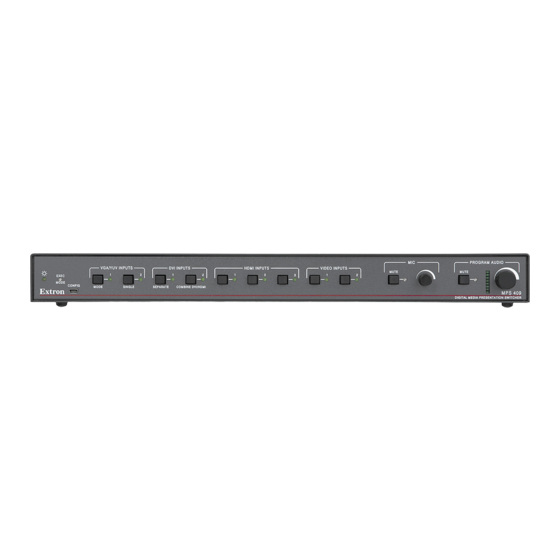
This guide provides basic instructions for an experienced technician to install, set up, and
operate the Extron
®
pages, line drawings are used to clarify steps discussed in the text. Installation and service
must be performed by authorized personnel only.
Installation
Step 1 —
Disconnect Power
Remove power from the switcher and all other devices that will be connected.
EXEC
MODE
CONFIG
MODE
Step 2 —
Mount the Switcher
The MPS 409 is housed in a full rack width, 8.5 inch deep, 1U high metal enclosure. Select a
mounting location, then choose an appropriate mounting option and mount the switcher.
100-240V
0.4A MAX
1
1
50/60 Hz
Step 3 —
Cable the Switcher
Make certain the MPS 409, all sources, and displays are powered off. Run all audio, video,
communication and power cables for operation.
a.
Attach up to two VGA/YUV (
input devices to the switcher.
b.
Connect the VGA/YUV output (
from the switcher to the appropriate display inputs.
c.
For stereo input, connect up to nine audio sources to each of the unbalanced stereo audio
input groups; VGA/YUV (
connector diagram on the right for wiring.
d.
For unbalanced stereo output, connect an output device to each of the
output groups; VGA/YUV (
See the 3.5 mm plug connector diagram on the right for wiring.
e.
Connect an audio amplifier to the Program Audio Output connectors.
See the connector diagram on the right for proper wiring.
f.
HDMI
(Optional) Connect a microphone to the rear Mic/Line connector
(see the figure at right). Refer to the microphone user guide for
1
3
proper wiring and phantom power requirements.
Set switch 2 of the DIP switch bank down (off) for a microphone. If
phantom power (+48V) is required, set switch 1 up (on).
2
OUTPUT
g.
(Optional) If the switcher is connected to a computer or host
controller for remote control, connect the host RS-232 cable to the
3-pin captive screw connector on the rear of the switcher (see the
figure at right).
Media Presentation Switcher, MPS 409. Where possible in the following
VGA/YUV INPUTS
DVI INPUTS
1
2
1
2
SINGLE
SEPARATE
COMBINE DVI/HDMI
b
c
VGA/YUV
2
OUTPUT
2
OUTPUT
DVI-D
l
m
b
), two DVI (
c
), DVI output (
d
n
), DVI (
), HDMI (
e
o
), DVI (
), HDMI (
1
1
3
OUTPUT
2
OUTPUT
2
HDMI INPUTS
VIDEO INPUTS
1
2
3
1
d
e
f
1
2
OUTPUT
1
2
1
2
OUTPUT
n
o
l
f
), three HDMI (
), and two composite video (
m
p
), HDMI output (
), and video (
g
i
), and Video (
). See the 3.5 mm plug
q
s
), and Video (
).
VIDEO
1
2
OUTPUT
L
L
L
R
R
R
MIC
MUTE
MUTE
2
g
h
HDMI
1
1
3
3
OUTPUT
OUTPUT
2
OUTPUT
2
p
q
r
Tip (L+)
Tip (+)
h
)
Sleeve ( )
RCA Connector
3.5 mm Stereo Plug Connector
r
) output
CAUTION
For unbalanced audio, connect the
sleeve(s) to the ground contact.
DO NOT
negative (-) contacts.
Tip
Ring
NO Ground Here
Sleeve(s)
Sleeve(s)
Tip
Ring
NO Ground Here
Balanced Output
Unbalanced Output
MPS 409
MIC/LINE
LEVEL
PROGRAM
+48V
AUDIO
OUT
MIC/LINE
L
R
RS-232
ON LINE
Tx Rx
ON
1 2
OFF MIC
(5 mm)
RS-232
MAX.
Device
Transmit (Tx)
Do not tin
Receive (Rx)
the wires!
_
Ground (
)
PROGRAM AUDIO
MPS 409
DIGITAL MEDIA PRESENTATION SWITCHER
i
VIDEO
1
2
OUTPUT
MI
L
L
L
LEV
PROGRAM
AUDIO
OUT
MIC/LIN
L
R
R
R
R
s
Ring
(R+)
Sleeve ( )
(unbalanced)
connect the sleeve(s) to the
Tip
Tip
(5 mm)
MAX.
Tip
Sleeve
Unbalanced Mic Input
Tip
Ring
Sleeve
Balanced Mic Input
Tx
Rx
Bidirectional
Transmit (Tx)
Receive (Rx)
_
Ground (
)
1
+
Advertisement
Table of Contents

Related Manuals for Extron electronics MPS 409


Summary of Contents for Extron electronics MPS 409
- Page 1 DIGITAL MEDIA PRESENTATION SWITCHER Step 2 — Mount the Switcher The MPS 409 is housed in a full rack width, 8.5 inch deep, 1U high metal enclosure. Select a mounting location, then choose an appropriate mounting option and mount the switcher. 100-240V 0.4A MAX...
- Page 2 DIGITAL MEDIA PRESENTATION SWITCHER Separate Switcher Mode Combined HDMI/DVI Mode Combined mode allows the MPS 409 to function as a 5x1 HDMI/DVI switcher. This is accomplished by switching a selected DVI or HDMI input to the HDMI video output, deactivating the video output.
- Page 3 If an input button is not pressed, the switcher times out and MODE CONFIG MODE SINGLE SEPARATE COMBINE DVI/HDMI MPS 409 exits audio level adjustment mode. DIGITAL MEDIA PRESENTATION SWITCHER 3. In audio adjustment mode, when an input button is pressed, the front Press input to Adjust input panel input LEDs indicate the current gain/attenuation setting.
- Page 4 Inside USA/Canada Only Inside Asia Only Inside China Only Inside USA/Canada Only Inside Europe Only 68-1833-50 +65.6383.4400 +86.21.3760.1568 +1.714.491.1500 +1.919.863.1794 +31.33.453.4040 +1.714.491.1517 FAX +65.6383.4664 FAX +86.21.3760.1566 FAX Rev. A +1.919.863.1797 FAX +31.33.453.4050 FAX 07 10 www.extron.com © 2010 Extron Electronics All Rights Reserved.
Need help?
Do you have a question about the MPS 409 and is the answer not in the manual?
Questions and answers