TESTO 6681 Instruction Manual
Humidity transmitter with ethernet module
Hide thumbs
Also See for 6681:
- Instruction manual (154 pages) ,
- Instruction manual (86 pages) ,
- Instruction manual (92 pages)

Related Manuals for TESTO 6681


Summary of Contents for TESTO 6681
- Page 1 6681 Ethernet · Humidity transmitter with Ethernet module testo 6610 · Probes P2A software · Parameterizing, adjusting and analyzing software Instruction manual Volume 1...
-
Page 3: S Afety And The Environment
Protecting the environment Send the product back to Testo at the end of its useful life. We will ► ensure that it is disposed of in an environmentally friendly manner. -
Page 4: About This Document
4 About this document About this document Please read this documentation through carefully and familiarize yourself ► with the product before putting it to use. Keep this document to hand so that you can refer to it when necessary. Hand this documentation on to any subsequent users of the product. - Page 5 A step is not numbered if there are no further steps or if the step is optional, e.g.: Insert probe connector into socket of testo 6681 until it engages. " to " Example entries are in inverted commas, e.g.: The value "0"...
-
Page 6: Table Of Contents
1.4.3 Password protection ..............70 1.4.4 Structure of user menu ............. 70 1.4.5 Overview of the testo 6681 user menu ..........72 1.4.6 The individual main menus ............74 1.5 Status, warning and error messages ............. 87 1.5.1 Status messages ..............87 1.5.2... - Page 7 Contents 7 1.5.3 Transmitter error messages ............90 1.5.4 Status codes in cyclical service ..........91 1.5.5 Handling alarm messages ............91 1.5.6 Namur fault conditions .............. 93 1.6 Maintenance and cleaning ..............94 1.6.1 Maintaining the instrument ............94 1.6.2 Cleaning the instrument ............
-
Page 8: Transmitter
Ethernet. Furthermore, it is possible to issue an alarm for those responsible for the process, if necessary. 1.1.2 Scope of delivery The scope of delivery of the testo 6681 humidity transmitter includes the following: Key cover ... -
Page 9: Accessories
6681 Ethernet - 1.1 Specifications 1.1.3 Accessories The following accessories are available for the testo 6681 humidity transmitter: Protection caps for probes Mains unit P2A software (parameterizing, adjusting and analyzing software) Assembly accessories. Information about accessories and their order numbers can be found in volume 2, chapter 4.2, page 179 or on the... - Page 10 6681 Ethernet - 1.1 Specifications Housing operating temperature -40 to +70 °C/-40 to +158 °F, with display from 0 to 50 °C/+32 to +122 °F With integrated relay: -40 - +60 °C Operating humidity 0...100 %rF Storage temperature - 40 to 80 °C/-40 to +176 °F Housing, weight Metal: 1.960 kg...
-
Page 11: Dimensions
6681 Ethernet - 1.1 Specifications 1.1.5 Dimensions Dimensions in mm With M 20 cable couplings With NPT cable couplings With M plug-in connections... -
Page 12: Product Description
R 3 and R 4 Earthing/PE connection 10 M 20 x 1.5 screw connection*, e.g. relay R 1 and R 2 11 Probe connector (testo 6610) 12 Upper part of housing Alternatively, NPT cable couplings or M plug-in... -
Page 13: Usable Probes
19 Hole for fastening to rear panel bracket (M3 x 6 screw) 20 Plastic bracket for assembly on rear panel 1.2.2 Usable probes The testo 6681 humidity transmitter can be used with the following probes: Probe Article no. Characteristic testo 6611 0555 6610-L11 Wall probe version;... -
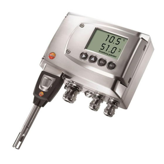
Page 14: Display And Keypad
-40 °C to +180 °C/-40 to +356 °F, sensor soldered 1.2.3 Display and keypad The display option allows the testo 6681 humidity transmitter to be operated via the display and four keys. The LCD display consists of two 7-segment lines for displaying readings and units and of an information line (for status messages, for example). -
Page 15: Analog Outputs
6681 Ethernet - 1.2 Product description 15 1.2.6 Analog outputs For analog outputs, the testo 6681 has either 2 or optionally 3 current outputs of 4 to 20 mA/0 to 20 mA (4-wire) or 2 or optionally 3 voltage outputs of 0 to 1 V/0 to 5 V/0 to 10 V (4-wire). -
Page 16: Scaling
6681 Ethernet - 1.2 Product description 1.2.8 Scaling There are three types of min./max. values: The measuring range The maximum sensor performance is in this range. Values outside of the measuring range are displayed via messages, for example. Refer to table (see below) for the measuring range. - Page 17 6681 Ethernet - 1.2 Product description 17 Standard scaling Measuring range measuring Physical Parameter Unit Probe range at 1013 hPa MIN MAX Temperature °C 6611 °F 6611 +158 +158 °C 6612 +150 +150 °F 6612 +302 +302 °C 6613...
-
Page 18: Alarm Handling
The testo 6681 monitors limit values using relays. If a reading is outside the limit values, a relay to be specified by the user is switched. -
Page 19: Commissioning
1.3.1 Insert Ethernet module (Order no. 0554 6656) The Ethernet module can be ordered retroactively as an accessory. It can easily be installed in the testo 6681 humidity transmitter. The probe connector must be disconnected. Loosen screw connection (1) of service flap and open the flap. - Page 20 6681 Ethernet - 1.3 Commissioning Place Ethernet module (A) on lower part of instrument (4). If necessary, manually set the address using the rotary encoder switches (see chapter 1.3.3.6, page 34 before fixing the instrument in place. Set on upper part of instrument (5) and fix in place using housing...
-
Page 21: Assembling The Instrument
6681 Ethernet - 1.3 Commissioning 21 1.3.2 Assembling the instrument 1.3.2.1 Wall mounting (for testo 6611/6613/6614/6615/6617 probes) Attaching rear panel bracket Remove locking screw (item (4) of drawing on page 21) and detach rear panel bracket from plastic bracket (item (2) of drawing on page 21). - Page 22 6681 Ethernet - 1.3 Commissioning Fastening instrument to rear panel bracket Slide plastic bracket (2) on the back of instrument onto rear panel bracket until it engages (see arrows). Insert screw (4) through hole (3) and screw into rear panel bracket.
- Page 23 6681 Ethernet - 1.3 Commissioning 23 1.3.2.2 Duct mounting (for testo 6612 probes) Hold wall/duct bracket (order no. 0554 6651) (6) against duct wall (8) and mark drill holes for wall/duct bracket and probe shaft. Drill a hole ( 12,5 mm) in the duct wall to feed through the probe shaft.
-
Page 24: Connecting The Instrument
6681 Ethernet - 1.3 Commissioning Slide plastic bracket (2) on the back of the transmitter onto bracket (3, 4) until it engages. Take the weight of the transmitter into account. Ensure that the brackets (4, 6) are fastened securely. - Page 25 6681 Ethernet - 1.3 Commissioning 25 Loosen and remove housing screws (2). Important. The Ethernet module (A) is already separated from the upper and lower parts of the instrument when the housing screws (2) are removed. Remove upper part of housing (3) and place on a clean surface.
- Page 26 6681 Ethernet - 1.3 Commissioning Warning! Electrical voltage. Danger of short-circuit! De-energize the mains connection before connecting the transmitter! Only have the transmitter wired and connected by authorized personnel with the voltage disconnected. 1.3.3.1 Overview of terminals Lower part of housing M 16 x 1.5 screw connection**...
- Page 27 6681 Ethernet - 1.3 Commissioning 27 The following description of the terminals refer to this overview and its numbering. 1.3.3.2 Connecting voltage supply and analog outputs Terminal strip for voltage supply and analog outputs (item (5) of Overview of terminals, chapter 1.3.3.1, page 26).
- Page 28 6681 Ethernet - 1.3 Commissioning Wiring diagram for 4-wire system (0 to 20 mA/4 to 20 mA/0 to 1 V/0 to 5 V/0 to 10 V) 20 to 30 V AC/DC 2 or 3 channels 0 to 20 mA/ 4 to 20 mA/ max.
- Page 29 6681 Ethernet - 1.3 Commissioning 29 1.3.3.3 Connecting the relay outputs Only have the transmitter wired and connected by authorized personnel with the voltage disconnected. Relay terminal strip (item (3) of Overview of terminals, chapter 1.3.3.1, page 26. There is the option of twelve terminals for a total of four relays. The designations NC/C/NO (normally closed contact/root or pin/normally open contact) are etched on the surface of the board.
- Page 30 6681 Ethernet - 1.3 Commissioning Connection note For the connection, a double-insulated mains cable (sheathed cable) with a cross-section of at least 1.5 sq. mm must be used. Cable connection (2) may not be routed in a loop within the tray (1).
- Page 31 6681 Ethernet - 1.3 Commissioning 31 Use of relay as NC contact (NC = normally closed) Alarm/status light (example of installation) 250 V AC/DC, 3 A The busy light (alarm/status light) is permanently on until the relay opens or the circuit is interrupted. This circuit can...
- Page 32 6681 Ethernet - 1.3 Commissioning The busy light (alarm/status light) only comes on when the relay is switched (closed). Monitoring the functionality of the alarm circuit is therefore not possible with this switching operation. Close M 20 x 1.5 screw connection (item (10) in Overview of terminals, chapter 1.3.3.1, page 26.
- Page 33 1.3.3.5 Creating the PE/earthing terminal As the testo 6681 has a metal housing, we recommend that the instrument be earthed. This can be done using the earthing terminal within the instrument (1) or the earthing terminal outside of the instrument (2).
- Page 34 XML server function (DIP switch No. 1 = off) integration of the testo 6681 into the customer's Ethernet system. Important: On delivery, the testo 6681 with Ethernet module is in Saveris mode (switch setting "on"). The testo 6681 must be disconnected from the Ethernet network.
- Page 35 6681 Ethernet - 1.3 Commissioning 35 Open transmitter (see Section Connecting the instrument, chapter 1.3.3, page 24). Set the DIP switch no. 1 (1) on the Ethernet module. In the illustration: DIP switch no. 1 off, DIP switch no. 2 on...
- Page 36 6681 Ethernet - 1.3 Commissioning For the configuration of the Ethernet module, see following chapter. If you do not wish to perform a configuration, close the transmitter (see chapter 5, page 36).
- Page 37 6681 Ethernet - 1.3 Commissioning 37 1.3.3.7 Closing the instrument Place Ethernet module (A) on lower part of instrument (1). Set on upper part of instrument (2) and fix in place using housing screws (3).
-
Page 38: Ethernet Communication
In general, the Ethernet module performs two functions: a corresponding testo 6681 becomes a Saveris subscriber a corresponding testo 6681 can be integrated into any Ethernet systems 1.3.4.2 Network connection • Connect the Ethernet network cable to the transmitter via the Ethernet socket. - Page 39 The IP address of the transmitter can either be set via the P2A software (transmitter accessories) or via the configuration menu of testo Saveris (testo Saveris Startup Wizard). Set IP address with the P2A software (see Chapter 3.3) or with the testo Saveris Startup Wizard (see instruction manual). Using Saveris ...
- Page 40 6681 Ethernet - 1.3 Commissioning The Testo Saveris software program window is opened with the Select project dialogue. If the software will not start, check whether the testo tdassvcs service is started in the service management of the operating system and restart it, if needed.
- Page 41 Example of an upload via the program wget: IP address = 254.169.100.100 URL for / deviceident.xml: H:/wget/wget-complete-stable/wget--post-file= C:/usersettings.xml 193.168.1.5/config/setusersettings The Ethernet module supports reading out of Readings Instrument type (testo 6681) Firmware date and version (testo 6681) Status and status messages (testo 6681)
- Page 42 6681 Ethernet - 1.3 Commissioning Alarm messages (testo 6681) Service hour counter (testo 6681 and probe) as well as the reading and writing of the: Adjustment data (testo 6681) Configuration data of analog outputs (testo 6681) ...
- Page 43 6681 Ethernet - 1.3 Commissioning 43 Description Parameter Answer (see Appendix) param=2 (relay 3) param=3 (relay 4) Read off sensor heating /config/getheatertime heatertime.xml information Read off options of /config/getoptions options.xml transmitter Read off alarm messages /config/getcollectivealarm collectivealarm.xml of transmitter...
- Page 44 6681 Ethernet - 1.3 Commissioning Elements in calibration.xml XML tag Description Type Base element. Contains the child calibration_data elements unit, attenuation, cal_reserved, cal_offset, cal_scale. unit See general elements attenuation Damping (0 - 15) Numerical, whole number cal_offset Offset Numerical, decimal number Parent element.
- Page 45 6681 Ethernet - 1.3 Commissioning 45 Elements in hourscount.xml XML tag Description Type hourcount Base element. Contains the child element hours hours Service hour counter in h Numerical, whole number Elements in identification.xml XML tag Description Type Base element. Contains the child...
- Page 46 6681 Ethernet - 1.3 Commissioning relay_number, relay_status, sw_point_character, sw_point_value, hysteresis_value Measurement channel linked to the relay_channel Numerical, whole number relay relay_number Relay number (0 - 2) Numerical, whole number Status of relay relay_status 0 = off Numerical, whole number...
- Page 47 6681 Ethernet - 1.3 Commissioning 47 Elements in usersettings.xml XML tag Description Type Base element. Contains the child elements pressure, h2o2, usersettings setting_display, backlight, contrast, language, disp_msg, h2o2_prozess pressure Absolute pressure Numerical, decimal number h2o2 H2O2 value Numerical, decimal number...
- Page 48 6681 Ethernet - 1.3 Commissioning XML tag Description Type measurement_value See general elements Parent element. Contains the child meas_status elements min, max, mean connector_info Channel (transmitter/probe) ASCII channel_type Parameter details ASCII min. Minimum reading Numerical, decimal number max. Maximum reading...
- Page 49 6681 Ethernet - 1.3 Commissioning 49 If statemsg = 0 there are no new messages. If statemsg != 0: xxxx xxxx xxxx xxxx xxxx xxxx xxxx xxxx ││││ │││└- 1 = transmitter error ││││ ││└─ 1 = transmitter warning ││││...
- Page 50 6681 Ethernet - 1.3 Commissioning xml files Appendix Note: "xxxx" = text message calibration.xml <?xml version="1.0" encoding="UTF-8" ?> <calibration_data> <unit>%rF</unit> <attenuation>1</attenuation> <cal_offset>0.000000</cal_offset> <cal_scale> <cal_min_scale>0.000000</cal_min_scale> <cal_max_scale>0.000000</cal_max_scale> </cal_scale> </calibration_data> collectivealarm.xml <?xml version="1.0" encoding="UTF-8" ?> <colalarmtable> <alarm_numbers>4</alarm_numbers> <alarm> <alarm_event>xxxx</alarm_event> <alarm_state>0</alarm_state> </alarm> <alarm>...
- Page 51 6681 Ethernet - 1.3 Commissioning 51 firmwaredate.xml <?xml version="1.0" encoding="UTF-8" ?> <firmware_date> <year>2008</year> <month>3</month> <day>28</day> </firmware_date> heatertime.xml <?xml version="1.0" encoding="UTF-8" ?> <heatertime> <heatertimeoff>60</heatertimeoff> </heatertime> hourscount.xml <?xml version="1.0" encoding="UTF-8" ?> <hourcount> <hours>68</hours> </hourcount> identification.xml <?xml version="1.0" encoding="UTF-8" ?> <ident> <device_id>31</device_id>...
- Page 52 6681 Ethernet - 1.3 Commissioning <measurement_value> <value>42.4</value> <unit>%rF</unit> </measurement_value> <measurement_value> <value>9.5</value> <unit>td°C</unit> </measurement_value> </online_values> options.xml <?xml version="1.0" encoding="UTF-8" ?> <options> <device_options>00000011</device_options> <production_options>xxxx</production_options> </options> reldefinition.xml <?xml version="1.0" encoding="UTF-8" ?> <relay_data> <relay_channel>0</relay_channel> <relay_number>0</relay_number> <relay_status>0</relay_status> <sw_point_charact>0</sw_point_charact> <sw_point_value>0.0</sw_point_value> <hysteresis_value>0.0</hysteresis_value> </relay_data> serialnumber.xml <?xml version="1.0" encoding="UTF-8" ?>...
- Page 53 6681 Ethernet - 1.3 Commissioning 53 xml files Appendix <!ELEMENT serialnumber (number)> <!ELEMENT number (#PCDATA)> <!ELEMENT ident (device_id)> <!ELEMENT device_id (#PCDATA)> <!ELEMENT firmware_version(version)> <!ELEMENT version (#PCDATA)> <!ELEMENT firmware_date (year, month, day)> <!ELEMENT year (#PCDATA)> <!ELEMENT month (#PCDATA)> <!ELEMENT day (#PCDATA)>...
- Page 54 6681 Ethernet - 1.3 Commissioning <!ELEMENT contrast (#PCDATA)> <!ELEMENT language (#PCDATA)> <!ELEMENT disp_msg (#PCDATA)> <!ELEMENT h2o2_prozess (#PCDATA)> <!ELEMENT calibration_data (unit, attenuation, cal_offset, cal_scale)> <!ELEMENT attenuation (#PCDATA)> <!ELEMENT cal_offset (#PCDATA)> <!ELEMENT cal_scale (cal_minscale, cal_maxscale)> <!ELEMENT cal_minscale (#PCDATA)> <!ELEMENT cal_maxscale (#PCDATA)>...
- Page 55 6681 Ethernet - 1.3 Commissioning 55 status.xml <?xml version="1.0" encoding="UTF-8" ?> <mufstatus> <statemsg>0</statemsg> <staterel>0</staterel> <statecounter>1</statecounter> </mufstatus> usersettings.xml <?xml version="1.0" encoding="UTF-8" ?> <usersettings> <pressure>1013.0</pressure> <h2o2>0.0</h2o2> <setting_disp>1</setting_disp> <backlight>3</backlight> <contrast>5</contrast> <language>0</language> <disp_msg>1</disp_msg> <h2o2_prozess>0</h2o2_prozess> </usersettings> version.xml <?xml version="1.0" encoding="UTF-8" ?> <firmware_version> <version>V1.10</version> </firmware_version>...
- Page 56 6681 Ethernet - 1.3 Commissioning viewchannels.xml <?xml version="1.0" encoding="UTF-8" ?> <view_channels> <number_values>2</number_values> <view_channel> <channel_info> <connector_info>Probe</connector_info> <channel_type>Temperature</channel_type> </channel_info> <measurement_value> <value>23.7</value> <unit>°C</unit> </measurement_value> <meas_status> <min>23.6</min> <max>23.7</max> <mean>23.7</mean> </meas_status> </view_channel> <view_channel> <channel_info> <connector_info>Probe</connector_info> <channel_type>Humidity</channel_type> </channel_info> <measurement_value> <value>42.5</value> <unit>%rF</unit> </measurement_value> <meas_status> <min>41.7</min> <max>43.0</max>...
-
Page 57: Adjusting The Instrument
- digital signal chain. The testo 6681 transmitter has digital probes whose adjustment information is stored in the probes' internal memory. Both 1-point and 2-point adjustments can thus be carried out on another testo 6681 (e.g. in the calibration laboratory). - Page 58 In the 1-point adjustment, the reading at the working point is raised to the reference value so that there is no longer any deviation in the working point. The reference condition can be measured using a precise handheld instrument (e.g. testo 400/650 with precision humidity probe) or be created in an air conditioning cabinet.
- Page 59 Connect Testo handheld instrument 400/650 (1) with connected humidity reference probe (3) (order no. reference set 0699 3656/20) to the service interface (5) of the testo 6681 via the adjustment adapter (2) (connected to the probe socket 1 of the...
- Page 60 6681 Ethernet - 1.3 Commissioning Expose the humidity probe (4) of the testo 6681 and the reference probe (3) to the same reference conditions (e.g. in the humidity generator) and allow climatic conditions to equalize. Switch on the testo 400/650. The two-part display of the handheld instrument will show the values of the transmitter on the left, and the values of the reference probe on the right.
- Page 61 - 1.3 Commissioning 61 A 2-point adjustment cancels any previous 1-point adjustment. Adjustment with the standard Testo adjustment salt pots is not suitable for the testo 6614 (heated for high-humidity applications) and testo 6615 (trace humidity) probes. The reference conditions should be generated in a humidity generator to adjust these probes.
- Page 62 The service flap of the testo 6681 is open. Expose the humidity probe of the testo 6681 to the reference condition of 11.3 % RH for at least 1.5 hours at 25 °C. After this equalization period, press the 11.3 % adjustment key (4) for at least 10 seconds with something like a ball-point pen that is not too sharp.
-
Page 63: Analog Output Adjustment
6681 Ethernet - 1.3 Commissioning 63 Completion of the adjustment is signalled by the LED (1) coming on permanently and the Probe reset status message is shown. Carry out the adjustment analogously for the reference condition 75.3 % RH. Press on the 75.3 % RH adjustment key (6) to do this. - Page 64 (see chapter 1.4.6.9, page 83). Disconnect connections between multimeter and contacts of the testo 6681 and close service flap. Adjusting analog output 3 (optional) If the optional third analog output is to be adjusted, a cable connection to measure the analog value must be installed.
- Page 65 Mist With the testo 6614, the rear of the Testo humidity sensor is heated, creating a microclimate around the sensor (within the filter) that is constantly 5 K warmer than the actual process conditions. As can be seen in the Mollier diagram, this reduces the relative humidity at the sensor from around 100 % RH to a lower value, e.g.
- Page 66 This means that extremely accurate measuring results are also attained to -60 °Ctd. To this end, a temperature sensor is fitted on the back of the testo 6615 which is used as a heater. A humidity and temperature value pair is taken in both the unheated and heated state.
- Page 67 6681 Ethernet - 1.3 Commissioning 67 The process temperature should not vary by more than 0.5K The dew point temperature should remain stable, as far as possible The process pressure should not vary excessively If these prerequisites cannot be fulfilled, the values obtained during the last successful self-adjustment will be maintained.
-
Page 68: Operation
1.4.1 Relationship between user menu and mini-DIN socket is active The testo 6681 can be parameterized using either the user menu or the P2A software (see volume 2, chapter 2, page 103). The testo 6681 humidity transmitter can only be operated via the display and keypad if the display option is available. -
Page 69: Key Cover
6681 Ethernet - 1.4 Operation 69 1.4.2 Key cover To prevent unauthorized operation of the keys, the standard key frame can be replaced with a key cover. If the key cover has been assembled, the service flap must be opened for operation (see Section Opening the instrument, chapter 1.3.3, page 24). -
Page 70: Password Protection
6681 Ethernet - 1.4 Operation 1.4.3 Password protection The user menu can be protected with a four-digit numerical code (see Editing Main Menu Settings, chapter 1.4.6.5, page 77) so that access to the user menu is denied to unauthorized persons not familiar with this numerical code. - Page 71 6681 Ethernet - 1.4 Operation 71 Function/description In Measuring Mode: changes to parameterization In Parameterizing Mode: confirms a selection or setting Leaves a menu (without modifying any settings) Selecting: scrolls through menus (downwards) or selectable alternatives Editing: changes to next digit (to the right) Selecting: scrolls through menus (upwards) or selectable alternatives ...
-
Page 72: Overview Of The Testo 6681 User Menu
6681 Ethernet - 1.4 Operation 1.4.5 Overview of the testo 6681 user menu... - Page 73 6681 Ethernet - 1.4 Operation 73...
-
Page 74: The Individual Main Menus
1.4.6 The individual main menus 1.4.6.1 Editing main menu of channel 1 An overview is given in Overview of the testo 6681 user menu, chapter 1.4.5, page 72). You can perform basic settings for channel 1. In Measuring Mode, press SET, select Main Menu Channel 1 using ... - Page 75 6681 Ethernet - 1.4 Operation 75 1.4.6.3 Editing main menu of channel 3 (if this option is available) See channel 1. 1.4.6.4 Editing Main Menu Alarm With the alarm, the relays, available as options, are programmed. In addition, the alarm statuses are shown on the display (top right) (even without relays).
- Page 76 Using alarm as collective alarm or not using it at all If the collective alarm is assigned to an alarm, the relay is switched as soon as (at least) one of the warning or error messages of the testo 6681 transmitter (or the connected testo 6610 probe) is activated.
- Page 77 6681 Ethernet - 1.4 Operation 77 Specify with or whether Alarm x is to be used as the Alarm relay or is to be not used. Confirm selection with SET and return to Alarm x. Change to another alarm using or and perform settings in the same way.
- Page 78 6681 Ethernet - 1.4 Operation Contrast The brightness difference between the display background and the displayed values is changed. Edit/select parameter with or , confirm with SET or cancel entry with ESC (the effect of the change in parameter can be seen during input).
- Page 79 6681 Ethernet - 1.4 Operation 79 Using ESC return to H proportion by weight and continue to Absolute pressure unit using or . Selecting absolute pressure unit (Abs. pressure unit) This parameter determines the humidity variables, standardised atmospheric dewpoint (°CtA, °FtA), relative humidity (g/kg or gr/lb) and water content...
- Page 80 6681 Ethernet - 1.4 Operation 1.4.6.6 Editing Analysis main menu You can test the functionality of analog and relay outputs. In addition, you can read off the minimum and maximum values (since the last voltage supply or reset of the min./max. values).
- Page 81 6681 Ethernet - 1.4 Operation 81 Return to Test Analog Output using ESC and continue to Test Relay Output using or . Testing functionality of relay outputs Press SET, choose between Alarm 1, 2, 3, 4 with or .
- Page 82 6681 Ethernet - 1.4 Operation 1.4.6.7 Editing Message main menu Messages can be confirmed/acknowledged, the last messages can be called up and the display of the messages can be switched on or off. Operating hours at the time of...
- Page 83 6681 Ethernet - 1.4 Operation 83 1.4.6.8 Calling up Main Menu Ident 6681 Instruments or probe type 2.01 Firmware version Serial 11111111 Serial number The serial numbers of the transmitter and probe can be read off. In Measuring Mode, press SET, select Main Menu Ident using ...
- Page 84 6681 Ethernet - 1.4 Operation Enter reference value for 1-point adjustment Please also refer to chapter 1.3.5.2, page 58. In Measuring Mode, press SET, select Main Menu Adjust using or and confirm selection with SET. Reference value % RH is displayed.
- Page 85 6681 Ethernet - 1.4 Operation 85 The adjusted measurement values appear after probe reset. Performing analog adjustment Please refer to chapter 1.3.5.4, page 63. In Measuring Mode, press SET, select Main Menu Adjust using or and confirm selection with SET.
- Page 86 6681 Ethernet - 1.4 Operation 1.4.6.10 Editing Reset main menu You can reset the factory settings for the following: Instrument Sensor/probe Min./max. values Resetting to the factory settings means resetting to the order specification, i.e. the specific condition at the time of supply to the customer.
-
Page 87: Status, Warning And Error Messages
Warning messages and Error messages for either the testo 6681 or the connected testo 661x probe as applicable. All messages are stored in the transmitter with an operating hours stamp. Use the user menu (see chapter 1.4.6.7, page 82) or P2A software (see volume 2, chapter 2, page 103) to view the message history. -
Page 88: Warning Messages
2-point adjustment 80 % As part of the 2-point adjustment, an adjustment is performed at 80 % RH 02105 Self-adjustment active For testo 6615 probe only: The probe performs an automatic self-adjustment 02518 Probe reset Probe reset: The probe performs a reset 1.5.2 Warning messages... - Page 89 2-point adjustment where necessary) If the problem persists, contact Testo Service 02809 Sensor early For testo 6617 probe only: Carry out visual warning* The cover electrode of the inspection sensor is damaged; this If the mirror-like surface of may soon cause the sensor...
-
Page 90: Transmitter Error Messages
T sensor short- Short-circuit in temperature Contact Testo Service circuit sensor 0300D T sensor broken The temperature sensor is Contact Testo Service damaged (sensor broken) 03105 Self-adjustment For testo 6615 probe only: Contact Testo Service error The automatic self- adjustment was faulty... -
Page 91: Status Codes In Cyclical Service
6681 Ethernet - 1.5 Status, warning and error messages 1.5.4 Status codes in cyclical service 1.5.4.1 Status codes for error messages Message Description Cause (Hexdecimal code) No probe connected 0x08 No communication Wrong probe connected Communication with probe interrupted... - Page 92 6681 Ethernet - 1.5 Status, warning and error messages Shown on the Message Can be used for collective alarm display start/end 2-point adjustment drift* T ambient high** T ambient low** Supply voltage low** T process high** Condensation* Values less than...
-
Page 93: Namur Fault Conditions
6681 Ethernet - 1.5 Status, warning and error messages 1.5.6 Namur fault conditions If the faults named in the following table occur, the analog outputs output special values that enable a general fault warning in the higher-level control system. The values correspond to the "Namur" industry standard. -
Page 94: Maintenance And Cleaning
6681 Ethernet - 1.6 Maintenance and cleaning 1.6 Maintenance and cleaning 1.6.1 Maintaining the instrument We recommend that the adjustment and settings of the transmitter be checked at regular intervals using the User menu (chapter 1.4, page 68) or ... - Page 95 6681 Ethernet - 1.6 Maintenance and cleaning 95...
- Page 96 6681 Ethernet - 1.6 Maintenance and cleaning...
- Page 100 0970 6687 en 04 V01.20 V01.70-1 en-GB Vol1...
Need help?
Do you have a question about the 6681 and is the answer not in the manual?
Questions and answers