
Related Manuals for TESTO 6682


Summary of Contents for TESTO 6682
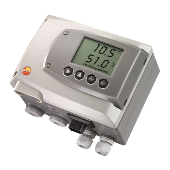
- Page 1 6682 Humidity transmitters testo 6616 Probes For use in areas with risk of explosion according to Directive 94/9/EC (ATEX) Instruction manual...
- Page 2 2 Safety Notes for installation Observe the installation and safety instructions from the instruction ► manual. Perform the installation according to the manufacturer's specifications ► and the valid standards and regulations. Only use the instruments in measurement substances against which the ►...
- Page 3 Safety 3 Safety Installation, electrical connection, commissioning, operation and maintenance of the measuring system can only be performed by trained personnel authorized by the system operator. The trained personnel must have read and understood this instruction manual and follow the directions specified within it.
- Page 4 Follow the prescribed steps exactly. Use only OEM spare parts from testo. Environment Protecting the environment Send the product back to testo at the end of its useful life. We will ensure ► that it is disposed of in an environmentally friendly manner.
- Page 5 About this document 5 About this document Please read this documentation through carefully and familiarize yourself ► with the product before putting it to use. Keep this document to hand so that you can refer to it when necessary. Hand this documentation on to any subsequent users of the product.
- Page 6 A step is not numbered if there are no further steps or if the step is optional, e.g.: ▪ Insert probe connector into socket of testo 6682 until it engages. " ... " Example entries are in inverted commas, e.g.: The value "0"...
-
Page 7: Table Of Contents
1.1.2 Scope of delivery.................9 1.1.3 Accessories................10 1.1.4 Technical data................10 1.1.5 Dimensions ................11 1.1.6 EC declaration of conformity for testo 6682......12 1.2 Product description ................13 1.2.1 At a glance ................13 1.2.2 Usable probes ................14 1.2.3 Display and keypad..............14 1.2.4 Analog outputs ................14 1.2.5... - Page 8 2.3.2 Connecting/removing the probe to/from the transmitter ... 64 2.4 Maintenance and cleaning..............65 2.4.1 Exchanging filter protection cap for testo 6616 probe ....65 2.4.2 Cleaning the instrument and filter protection cap ..... 66 2.4.3 Exchanging probe ..............66 ................
-
Page 9: Transmitter
- 1.1 Specifications 9 Transmitter 1.1 Specifications 1.1.1 Functions and use The testo 6682 humidity transmitter is used in conjunction with the plug-in, adjusted testo 6616 probe. Please refer to Chapter testo 6616 probe, page 52 for information about commissioning, operating and maintaining the testo 6616 probe. -
Page 10: Accessories
6682 - 1.1 Specifications 1.1.3 Accessories The following accessories are available for the testo 6682 humidity transmitter: Protection caps for probes Assembly accessories Information about accessories and their order numbers can be found in Chapter Accessories and spare parts, page 68 or on the website at www.testo.com. -
Page 11: Dimensions
6682 - 1.1 Specifications 11 Protection class Warranty IP 65 only if the transmitter is wired Duration: 2 years and/or seal plugs are inserted and Warranty conditions, see the probe is plugged in www.testo.com/warranty Directives, standards and tests 94/9/EC (ATEX) EC Directive: 2004/108/EC 1.1.5 Dimensions... -
Page 12: Ec Declaration Of Conformity For Testo 6682
6682 - 1.1 Specifications 1.1.6 EC declaration of conformity for testo 6682... -
Page 13: Product Description
M 16 x 1.5 screw connection, cable entry Earthing/PE connection Eyelet for measuring point panel Probe connector (testo 6616) 10 Upper part of housing 11 Housing screws 13 Hole for fastening to rear panel bracket (M3 x 6 screw) -
Page 14: Usable Probes
Brightness and contrast of the display can be changed via the user menu. 1.2.4 Analog outputs As analog outputs the testo 6682 has 2 current outputs of 4 to 20 mA (2- wire), where channel 1 is used for the supply. -
Page 15: Parameters
6682 - 1.2 Product description 15 1.2.5 Parameters The following parameters are calculated: Relative humidity in %RH (technical) Relative humidity in % WMO* (calculation according to the WMO standard) Temperature °C and °F Dewpoint or pressure dewpoint in °Ctd and °Ftd* ... - Page 16 (Min. value of standard) - (50 % of X) - It is thus possible to scale beyond the measuring range, e.g. for the adjustment of the scaling limits to standard values of a PLC. Measuring ranges with testo 6616 probe Standard scaling...
-
Page 17: Commissioning
6682 - 1.3 Commissioning 17 1.3 Commissioning 1.3.1 Wall mounting Attaching rear panel bracket Ex protection! Observe the general protective measures when working in areas with risk of explosion. 1. Remove locking screw (item (4) of drawing on page 18) and detach rear panel bracket from plastic bracket (item (2) of drawing on page 18). - Page 18 6682 - 1.3 Commissioning Fastening instrument to rear panel bracket 1. Slide plastic bracket (2) on the back of instrument onto rear panel bracket until it engages (see arrows). 2. Insert screw (4) through hole (3) and screw into rear panel bracket.
-
Page 19: Connecting The Instrument
- 1.3 Commissioning 19 1.3.2 Connecting the instrument Ex protection! Each of the two channels of the testo 6682 must be provided with a certified transmitter power supply unit that provides a category ia circuit. The technical data of the transmitter power supply unit must... - Page 20 6682 - 1.3 Commissioning 2. Loosen and remove housing screws (2). 3. Remove upper part of housing from lower part (3) and place on a clean surface. Warning! Electrical voltage. Danger of injury! De-energize the power supply before connecting the...
- Page 21 6682 - 1.3 Commissioning 21 1.3.2.1 Overview of terminals Lower part of housing Terminal strips for voltage supply and analog outputs Terminal board Earthing terminal (internal) M 16 x 1.5 screw connection Earthing terminal (external) Eyelet for measuring point panel The following description of the terminals refer to this overview and its numbering.
- Page 22 6682 - 1.3 Commissioning 1.3.2.2 Connecting voltage supply and analog outputs Terminal strips for current loop/analog output (item (2) (see Chapter Overview of terminals, page 21)) 1. Feed cable with voltage supply and analog signal lines from certified power supply unit through opened M 16 x 1.5 screw connection (item (5) (see Chapter Overview of terminals, page 21)).
- Page 23 The testo 6682 must be integrated into the equipotential bonding. Observe the following instructions for this. Integrate the metal housing of the testo 6682 into the equipotential bonding to prevent the danger of an electrostatic charge. This can be done using the earthing terminal within the instrument (1) or the earthing terminal outside of the instrument (2).
- Page 24 6682 - 1.3 Commissioning Using the earthing terminal within the instrument 1. Guide PE line (yellow-green) (5) through the cable coupling (x) and fit cable lug (8). Fix this to the side of the instrument (6) using M 5 screw (3), washer (4) and snap ring (7) on the internal earthing terminal (1).
-
Page 25: Adjusting The Instrument
- digital signal chain. The testo 6682 transmitter has digital probes whose adjustment information is stored in the probes' internal memory. Both 1-point and 2-point adjustments can thus be carried out on another testo 6682 (e.g. in the calibration laboratory). - Page 26 6682 - 1.3 Commissioning Adjustment of the analog outputs is only logical in combination with the testo 6682 transmitter used at the measuring point and the installed supply isolator. 1.3.3.1 Overview: Adjustment keys Adjust key 11.3 % Adjust key 75.3 % 1.3.3.2...
- Page 27 With the 2-point adjustment, the parameter is adjusted to the reference value at the two standard adjustment points 11.3 % RH and 75.3 % RH. The reference conditions are reached either by using the testo humidity adjustment set (order no. 0554 0660, consisting of humidity pots 0554 0635 (11.3 %), 0554 0636 (33 %) and 0554 0637 (75.3 %)) or in the humidity...
- Page 28 6682 - 1.3 Commissioning Ex protection! In Ex area Zone 1 and Zone 2, only use the following humidity pots: 0554 0635 (11.3 %), 0554 0636 (33 %) or 0554 0637 (75.3 %). Remove humidity pots from the packaging (cardboard box and styrofoam) outside of the Ex area.
- Page 29 (salt pots) (humidity generator) The service flap of the testo 6682 is open (see Chapter Opening the instrument, page 19). 1. Expose the humidity probe of the testo 6682 to the reference condition of 11.3 % RH for at least 1.5 hours at 25 °C.
- Page 30 The purpose of adjusting the analog outputs is to adjust the signal chain from the digital signal (within the transmitter) to the analog outputs. This adjustment is only logical in combination with the testo 6682 transmitter used at the measuring point and the installed supply isolator.
- Page 31 6682 - 1.3 Commissioning 31 4. Perform the second and third adjustment points (step 2 and 3) specified by the user menu in accordance with the adjustment. 5. Remove the multimeter from the current loop and close the current...
-
Page 32: Operation
6682 - 1.4 Operation 1.4 Operation The testo 6682 can be parameterized via the integrated user menu. 1.4.1 Key cover To prevent unauthorized operation of the keys, the standard key frame can be replaced with a key cover. If the key cover has been assembled, the service flap must be opened for operation (see Chapter Opening the instrument, page 19). -
Page 33: Password Protection
6682 - 1.4 Operation 33 1.4.2 Password protection The user menu can be protected with a four-digit numerical code (see Chapter Editing code settings, page 40) so that access to the user menu is denied to unauthorized persons not familiar with this numerical code. - Page 34 6682 - 1.4 Operation Function/description In Measuring Mode: changes to parameterization In Parameterizing Mode: confirms a selection or setting Leaves a menu (without modifying any settings) Selecting: scrolls through menus or selectable alternatives Editing: changes to next digit (to the right) Selecting: scrolls through menus or selectable alternatives ...
-
Page 35: Overview Of The Testo 6682 User Menu
6682 - 1.4 Operation 35 1.4.4 Overview of the testo 6682 user menu... - Page 36 6682 - 1.4 Operation...
-
Page 37: The Individual Main Menus
1.4.5.1 Editing Main Menu Channel 1 An overview is given in Overview of the testo 6682 user menu (see page 35). You can perform basic settings for channel 1. 1. In Measuring Mode, press SET, select Main Menu Channel 1 using ... - Page 38 6682 - 1.4 Operation 1.4.5.2 Editing main menu of channel 2 See channel 1. 1.4.5.3 Processing main menu Alarm The alarm stati are shown in the display. The alarms are used to monitor limit values, and can be viewed via the main menu Messages. For limit value monitoring, a selection can be made between minimum and maximum monitoring, and a limit value and a hysteresis can be set per alarm.
- Page 39 6682 - 1.4 Operation 39 1.4.5.4 Editing Main Menu Settings You can edit instrument settings and other settings. ▪ In Measuring Mode, press SET, select Main Menu Settings using or and confirm selection with SET. You can edit settings for: Display ...
- Page 40 6682 - 1.4 Operation Editing code settings You can set the access code (password). If a code other than "0000" (factory setting) is set, the transmitter can only be operated once this code has been entered via the menu.
- Page 41 6682 - 1.4 Operation 41 Editing absolute pressure (Abs. pressure value) You can set a value for the process absolute pressure. 1. Using or select (Abs. pressure value) and confirm selection with SET. The absolute pressure is displayed.
- Page 42 6682 - 1.4 Operation 2. Press SET, choose between Analog Output 1, 2 with or . 3. Press SET, scroll one digit to the right using , increase value of digit by 1 using . Any analog output value can be predefined, e.g. for an analog output of 4 to 20 mA, the value "6.0 mA".
- Page 43 6682 - 1.4 Operation 43 1.4.5.6 Editing Message main menu The last messages can be called up and the display of the messages can be switched on or off. Operating hours at the time of message Message number/number of messages present Example: "4/7"...
- Page 44 6682 - 1.4 Operation 1.4.5.7 Calling up Main Menu Ident 6682 Instruments or probe type 2.01 Firmware version Serial 11111111 Serial number The serial numbers of the transmitter and probe can be read off. 1. In Measuring Mode, press SET, select Main Menu Ident using or ...
- Page 45 6682 - 1.4 Operation 45 Enter reference values for 1-point adjustment Please also refer to Chapter 1-point adjustment (offset), page 1. In Measuring Mode, press SET, select Main Menu Adjust using or and confirm selection with SET.
- Page 46 6682 - 1.4 Operation Performing analog adjustment Please refer to Chapter 2-point adjustment, page 27 1. In Measuring Mode, press SET, select Main Menu Adjust using or and confirm selection with SET. Reference value % RH is displayed.
- Page 47 6682 - 1.4 Operation 47 1.4.5.9 Editing Reset main menu You can reset the factory settings for the following: Instrument Probes Min./max. values Resetting to the factory settings means resetting to the order specification, i.e. the specific condition at the time of supply to the customer.
-
Page 48: Status, Warning And Error Messages
All messages can be stored in the transmitter with an operating hours stamp. Use the user menu (see Chapter Editing Message main menu, page 43) to view the message history. 1.5.1 Status messages Status messages show the current operating mode of the testo 6682. Message Display Description 00300... -
Page 49: Transmitter Warning Messages
6682 - 1.5 Status, warning and error messages 49 Message Display Description 02102 2-point adjustment As part of the 2-point adjustment, an adjustment 1.3 % is performed at 11.3 % RH 02103 2-point adjustment As part of the 2-point adjustment, an adjustment 75.3 %... -
Page 50: Error Messages
Wrong probe The connected probe Use a compatible probe is not compatible with the Note: Probe 6616 belongs present transmitter to transmitter 6682 01528 Watchdog error Due to a processor error, If the problem occurs the transmitter performs frequently, contact Testo... -
Page 51: Maintenance And Cleaning
6682 - 1.6 Maintenance and cleaning 51 1.5.4 Namur fault conditions If the faults named in the following table occur, the analog outputs output special values that enable a general fault warning in the higher-level control system. The values correspond to the "Namur" industry standard. -
Page 52: Testo 6616 Probes
The testo 6616 probe can only be operated with the testo 6682 transmitter. The plug-in, adjusted testo 6616 probe is used together with the testo 6682 humidity transmitter and is suitable for use in areas with risk of explosion. These measuring units are suitable for the following applications, for... - Page 53 - 2.1 Specifications 53 2.1.1.2 The testo humidity sensor With the testo humidity sensor, which has been in successful use and continually improved for more than ten years, the focus has from the very beginning been on both accuracy parameters, namely measuring uncertainty and long-term stability.
-
Page 54: Scope Of Delivery
6682 - 2.1 Specifications 2.1.1.3 Self-diagnosis The testo 6616 probe monitors its functionality itself and reports the following faults: Sensor breaks Sensor short-circuit Condensation The condensation message is issued at a reading of 100 % RH and deactivated once the readings are within the valid range. -
Page 55: Accessories
Accessories and spare parts, page 68) Wall bracket 2.2 Product description 2.2.1 Filter The following filters can be used for the testo 6616 probe: Filter* Article no.** Characteristic Length A (mm) M 03 0554 0758 Sintered PTFE filter as protection cap... -
Page 56: Testo 6616 Cable Probe
6682 - 2.2 Product description 2.2.2 testo 6616 cable probe When using the zone separator (0554 1795) the probe shaft can be located in Zone 0 of an area with risk of explosion. Ex protection! The separate safety instructions for electrical operating... - Page 57 6682 - 2.2 Product description 57 testo 6682 transmitter testo 6616 cable probe L - A Technical data Parameters Materials Humidity Plug: Plastic Temperature Cable: Plastic Probe shaft: Stainless steel Meas. range* Earth terminal: Stainless steel Humidity: 0 to 100 % RH Zone separation: Stainless steel Temperature: -30 to 150 °C /...
- Page 58 6682 - 2.2 Product description Temperature Reproducibility ±0.15 °C (0.27 °F) Better than ± 0.5 % RH Slope PT1000 1/3 class B Sensor Refer to the charts below for the correlation between temperature Response time without protective and accuracy.
- Page 59 6682 - 2.2 Product description 59 Measuring accuracy of testo 6616 probe ± Humidity error according to amount | % RH| as a factor of process humidity % RH % RH...
- Page 60 6682 - 2.2 Product description Temperature error as a factor of process temperature and temperature of electronics System error 6681 + probe, electronics 25 °C/+77 °F System error 6681 + probe, electronics -25 °C to +70 °C/-13 to +158 °F...
-
Page 61: Ec Declaration Of Conformity For Testo 6616
6682 - 2.2 Product description 61 2.2.3 EC declaration of conformity for testo 6616... -
Page 62: Commissioning
6682 - 2.3 Commissioning 2.3 Commissioning 2.3.1 Installing the probe The testo 6682 transmitter is operated with the testo 6616 probe. ▪ Install probe according to the application and the measuring and spatial conditions. Important: In processes with > 85 % RH, install the probe in a vertical position (filter pointing downwards). - Page 63 6682 - 2.3 Commissioning 63 Process mounting Connection equipotential bonding (earth terminal): Integrate probe into equipotential bonding. Clamp screw connection Order no. 0554 1795 1. Probe shaft 2. Union nut (of clamp screw connection) 3. Screw-in body (of clamp screw connection) A.
-
Page 64: Connecting/Removing The Probe To/From The Transmitter
2.3.2 Connecting/removing the probe to/from the transmitter Insert probe connector into socket of testo 6682 until it engages. The testo 6682 identifies which probe is connected. To remove the probe, the lock release button on the probe must be... -
Page 65: Maintenance And Cleaning
6682 - 2.4 Maintenance and cleaning 65 2.4 Maintenance and cleaning 2.4.1 Exchanging filter protection cap for testo 6616 probe Zone separator Do not damage the sensors when exchanging the filter protection cap and do not touch their surfaces! 1. -
Page 66: Cleaning The Instrument And Filter Protection Cap
6682 - 2.4 Maintenance and cleaning Screw filter protection cap on by hand. 2.4.2 Cleaning the instrument and filter protection cap Ex protection! Only perform cleaning work in Ex-free room. ▪ Only clean the instrument carefully with a moist cloth. -
Page 67: Tips And Assistance
When does a stable current reading After approx. 20 seconds appear? If we could not answer your question, please contact your dealer or Testo Customer Service. For contact details see the rear side of this document or the web page www.testo.com/service-contact... -
Page 68: Accessories And Spare Parts
68 3.2 Accessories and spare parts 3.2 Accessories and spare parts Designation Article no. Fastenings, assembly aids Wall/duct bracket for fastening the transmitter to the probe and the 0554 6651 probe to the wall/duct Pressure-tight G 1/2" clamp screw connection up to 10 bar 0554 1795 Sensor filters and protective caps Sintered PTFE filter as protection cap... -
Page 69: Ordering Options For Testo 6682 Transmitter (0555 6682)
3.2 Accessories and spare parts 69 3.2.1 Ordering options for testo 6682 transmitter (0555 6682) Order code Characteristic Version Currently no further selection of variants Analog output 4 to 20 mA (via intrinsically safe supply isolator) Display with display/English with display/German... - Page 70 /Min/Max /Min/Max gr/ft /Min/Max /min/max °C /Min/Max (wet bulb) °F /Min/Max (wet bulb) kJ/kg /Min/Max (enthalpy) hPa /Min/Max (water vapour partial pressure) inch H2O/Min/Max (water vapour partial pressure) %Vol/Min/Max Further languages can be requested from testo AG if needed.
-
Page 71: Ordering Options For Testo 6616 Probes (0555 6616)
3.2 Accessories and spare parts 71 3.2.2 Ordering options for testo 6616 probes (0555 6616) Order code Characteristic Protective filter M 03 Sintered PTFE filter as protection cap Probe length N 01 Probe length 1 m N 02 Probe length 2 m... - Page 72 0977 6682 en 01 V01.12...
Need help?
Do you have a question about the 6682 and is the answer not in the manual?
Questions and answers