
Related Manuals for TESTO 6781


Summary of Contents for TESTO 6781
- Page 1 6781 · Transmitter P2A software · Parameterizing, adjusting and analyzing Instruction manual...
-
Page 3: Safety And The Environment
Pos: 8 /TD/Sicherheit und Umwelt/Sicherheit gewährleisten/MUF 63xx/Fachpersonal @ 3\mod_1234794940409_79.doc @ 26337 @ @ 1 Any additional work must only be carried out by authorized personnel. Otherwise testo will not accept any responsibility for the proper functioning of the instrument after repair and for the validity... -
Page 4: About This Document
> At the end of its useful life, send the product to the separate collection for electric and electronic devices (observe local regulations) or return the product to Testo for disposal. Pos: 11 /TD/Überschriften/MUF/1 Zu diesem Dokument @ 3\mod_1234793991331_79.doc @ 26242 @ 1 @ 1 About this document Pos: 12 /TD/Sicherheit und Umwelt/Zu diesem Dokument/Verwendung/Verwendung (Standard) @ 0\mod_1173775068554_79.doc @ 337 @ 5 @ 1... -
Page 5: Table Of Contents
4.4.2. Password protection ..................26 4.4.3. Structure of user menu ..................27 4.4.4. Overview of the testo 6781 user menu............29 4.4.5. The individual main menus ................31 4.4.5.1. Editing main menu of channel 1............31 4.4.5.2. Editing Main Menu Alarm..............32 4.4.5.3. Editing Main Menu Settings .............33... - Page 6 3 Contents 4.4.5.5. Editing Message main menu ............35 4.4.5.6. Calling up Main Menu Ident............. 36 4.4.5.7. Editing Main Menu Adjust..............37 4.4.5.8. Editing Reset main menu ..............39 4.5. Status, warning and error messages ..........39 4.5.1. Status messages ................... 40 4.5.2.
- Page 7 3 Contents Tips and assistance................72 6.1. Questions and answers ..............72 6.2. Accessories and spare parts ............73 6.2.1. Ordering options for testo 6781 transmitter (0555 6781) ........74 Pos: 18 /TD/--- Seitenwechsel --- @ 0\mod_1173774430601_0.doc @ 283 @ @ 1...
-
Page 8: Transmitter
• Monitoring of humidity and temperature in medical compressed air or granulate driers Pos: 22 /TD/Leistungsbeschreibung/Lieferumfang/MUF 63xx/MUF 6781 @ 3\mod_1238162497483_79.doc @ 30275 @ 3 @ 1 4.1.2. Scope of delivery The scope of delivery of the testo 6781 transmitter includes the following: •... -
Page 9: Technical Data
4 Transmitter Pos: 24 /TD/Leistungsbeschreibung/Technische Daten/MUF 63xx/MUF 6781 @ 3\mod_1238162594608_79.doc @ 30296 @ 355555555555555555555555555 @ 1 4.1.4. Technical data Parameter • Dewpoint temperature Measuring range at 25 °C • -90 to -20 °C Meas. uncertainty -20 °C to -40 °C : +/-1,5 K -40 °C... - Page 10 4 Transmitter Response time ≤ 3 s when changing from -75 °C to -30 °C ≤ 9 s when changing from -75 °C to -30 °C ≤ 300 s when changing from -30 °C to -75 °C ≤ 1080 s when changing from -30 °C to -75 °C Resolution Measuring range...
- Page 11 4 Transmitter Maximum load 4-wire: 500 Ω (power output) • Minimum load resistance • 4-wire: 10 kΩ (voltage output) Analog output • 0 to 1 V ± 1.5 mV (4-wire) or • 0 to 5 V ± 7.5 mV (4-wire) or •...
- Page 12 Directives, standards and tests • EC Directive: 2004/108/EC • 6781 was manufactured in accordance with EC pressure equipment Directive 97/23/EC, Article 3 Paragraph 3 as per "sound engineering practice", taking the regulations to be observed into account. Warranty •...
-
Page 13: Dimensions
4 Transmitter Pos: 25 /TD/Leistungsbeschreibung/Technische Daten/MUF 63xx/MUF 6781 Abmessungen @ 3\mod_1239806330094_79.doc @ 31183 @ 3 @ 1 4.1.5. Dimensions... -
Page 14: Product Description
4 Transmitter Pos: 26 /TD/Überschriften/MUF/5.2/6.2 Produktbeschreibung @ 3\mod_1234258723551_79.doc @ 24008 @ 2 @ 1 4.2. Product description Pos: 27 /TD/Produktbeschreibung/Übersicht/MUF 63xx/Systemkomponenten 6781 @ 3\mod_1239868226476_79.doc @ 31305 @ 3 @ 1 4.2.1. System components Application System components A With clean air and a process pressure •... -
Page 15: At A Glance
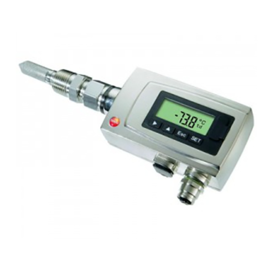
De-pressurized tube required during installation. • testo 6781 with N1/2" thread Pos: 28 /TD/Produktbeschreibung/Übersicht/MUF 63xx/Auf einen Blick MUF 6781 @ 3\mod_1238165303035_79.doc @ 30317 @ 3 @ 1 4.2.2. At a glance 1 Display (optional) 2 Keys (only with optional display) 3... -
Page 16: Display And Keypad
4 Transmitter Pos: 29 /TD/Produktbeschreibung/Übersicht/MUF 63xx/Display und Tastatur 6781 @ 4\mod_1250064749770_79.doc @ 47423 @ 3 @ 1 4.2.3. Display and keypad The display option allows operation of the testo 6781 transmitter via the display and four keys. The LCD display consists of one 7-segment line for displaying readings and units and of an information line (for status messages, for example). -
Page 17: Scaling
4 Transmitter 4.2.7. Scaling There are three types of min./max. values: 1 The measuring range: The maximum sensor performance is in this range. Values outside of the measuring range are displayed via messages, for example. Measuring range, see table (below). 2... -
Page 18: Commissioning
4 Transmitter 4.3. Commissioning Pos: 36 /TD/Erste Schritte/MUF 63xx/Mechanische Montage 6781 @ 3\mod_1239807163104_79.doc @ 31204 @ 3444 @ 1 4.3.1. Mechanical assembly • Carefully perform assembly work. • Take special care with leaktightness. We recommend inserting a metal sealing ring (internal diameter 21 mm). -
Page 19: Without Stainless Steel Measurement Chamber And Cooling Coil
4.3.1.2. With stainless steel measurement chamber (max. 35,000 hPa) 1. S crew process connection (G1/2) of the testo 6781 transmitter into the thread of the measurement chamber. 2. Mount 6781 as described under Without stainless steel measurement chamber and cooling coil page 19. -
Page 20: With Stainless Steel Measurement Chamber And Cooling Coil (Max. 35,000 Hpa)
4. Engage second quick-release fastening of the cooling coil in the standardized socket of the compressed air line. Pos: 37 /TD/Erste Schritte/MUF 63xx/Spannungsversorgung/Analogausgänge anschließen 6781 @ 3\mod_1239951683334_79.doc @ 31673 @ 45 @ 1 4.3.1.4. Connecting voltage supply and analog outputs Wiring diagram for 4-wire system (0 …... -
Page 21: Plug-In Connection For Power Supply And Channel
Pos: 39 /TD/Überschriften/MUF/5.3.3 Gerät abgleichen @ 3\mod_1236081099337_79.doc @ 27173 @ 3 @ 1 4.3.2. Adjusting the instrument Pos: 40 /TD/Erste Schritte/MUF 63xx/Wichtige Informationen zur Inbetriebnahme Selbstabgleich 6781 @ 7\mod_1282141902930_79.doc @ 69363 @ 455 @ 1 4.3.2.1. Init. phase during commissioning In order to achieve the specified high accuracy down to -90°Ctd... -
Page 22: Self-Adjustment
After approx. 5 hrs: The reading Init. phase disappears from the display, the instrument has reached optimal capacity. Pos: 41 /TD/Erste Schritte/MUF 63xx/1-Punkt-Abgleich 6781 @ 3\mod_1239794807174_79.doc @ 31163 @ 44 @ 1 4.3.2.2. Self-adjustment Conventional residual moisture sensors reveal extremely increasing measurement uncertainties in case of low moisture values, which are mainly caused by hysteresis effects. - Page 23 4 Transmitter The graph shows the effect of the self-adjustment, e.g. during the Init. phase. 1 Self-adjustment 2 Correction of measurement value 3 Process dew point temperature For the effectiveness of the self-adjustment the following prerequisites are decisive over the duration of the self-adjustment. •...
- Page 24 P2A software, see Setting cycle time of the self-adjustment page 37 and Self-adjustment page 59. Deactivating the self-adjustment function of the testo 6781 will reduce measuring accuracy and should therefore be restricted to the shortest possible length of time.
-
Page 25: 1-Point Adjustment By Entering A Reference Value
✓ A reference measuring instrument (e.g. chilled mirror dew point hygrometer) is at hand. 1. Expose the reference measuring instrument and the testo 6781 to the same, constant conditions and wait until the end of the automatic initialization phase. -
Page 26: Operation
4.4.1. Relationship between user menu and mini-DIN socket is active The testo 6781 can be parameterized using either the user menu or the P2A software (see Parameterizing, adjusting and analyzing software (P2A software) page 47). The testo 6781 transmitter can only be operated via the display and keypad if the display option is available. -
Page 27: Structure Of User Menu
4 Transmitter Pos: 46 /TD/Produkt verwenden/MUF 63xx/Aufbau des Bedienmenüs 6781 @ 3\mod_1239692809877_79.doc @ 31123 @ 3 @ 1 4.4.3. Structure of user menu At the main menu level, the user menu comprises the following: • Main Menu Channel 1 •... - Page 28 4 Transmitter Function/description • Selecting: scrolls through menus (upwards) or selectable alternatives • Editing: increases the value of the current digit by 1...
-
Page 29: Overview Of The Testo 6781 User Menu
4 Transmitter Pos: 47 /TD/Produkt verwenden/MUF 63xx/Übersicht Bedienmenü @ 3\mod_1234510821302_79.doc @ 25303 @ 3 @ 1 4.4.4. Overview of the testo 6781 user menu... - Page 30 4 Transmitter...
-
Page 31: The Individual Main Menus
Edit/select parameter with or , confirm with or abort entry with ESC. 2. Continue to the main menu with or or return to Measuring Mode with ESC. Pos: 49 /TD/Produkt verwenden/MUF 63xx/Hauptmenü Alarm bearbeiten 6781 @ 4\mod_1244645622570_79.doc @ 44953 @ 455 @ 1... -
Page 32: Editing Main Menu Alarm
4 Transmitter 4.4.5.2. Editing Main Menu Alarm The alarm statuses are shown on the display. You can choose whether the alarm is to be used to monitor limit values or as a collective alarm. If an alarm is to be used to monitor limit values, you can choose between monitoring the minimum or maximum value and set a limit value and hysteresis for each alarm. -
Page 33: Editing Main Menu Settings
or or return to 5. Continue to Main Menu Settings Measuring Mode with ESC. Pos: 50 /TD/Produkt verwenden/MUF 63xx/Hauptmenü Einstellungen bearbeiten 6781 @ 4\mod_1244535897708_79.doc @ 44917 @ 455555 @ 1 4.4.5.3. Editing Main Menu Settings You can edit instrument settings and other settings. -
Page 34: Editing Main Menu Analysis
Conf. Init. Phase proceed to the Display settings. Pos: 51 /TD/Produkt verwenden/MUF 63xx/Hauptmenü Analyse bearbeiten 6781 @ 3\mod_1241425854399_79.doc @ 32344 @ 455 @ 1 4.4.5.4. Editing Main Menu Analysis You can check the function of analog outputs. In addition, you can read off the minimum and maximum values (since the last voltage supply or reset of the min./max. -
Page 35: Editing Message Main Menu
or or return to 2. Continue to Main Menu Message Measuring Mode with ESC. Pos: 52 /TD/Produkt verwenden/MUF 63xx/Hauptmenü Meldungen bearbeiten 6781 @ 3\mod_1240905240318_79.doc @ 32203 @ 4 @ 1 4.4.5.5. Editing Message main menu Messages can be confirmed/acknowledged, the last messages can be called up and the display of the messages can be switched on or off. -
Page 36: Calling Up Main Menu Ident
Measuring Mode with ESC. An overview of the messages can be found in Status, warning and error messages page 39 Pos: 53 /TD/Produkt verwenden/MUF 63xx/Hauptmenü Ident abfragen 6781 @ 3\mod_1239269378840_79.doc @ 31053 @ 4 @ 1 4.4.5.6. Calling up Main Menu Ident 1... -
Page 37: Editing Main Menu Adjust
3. Continue to Main Menu Adjust Measuring Mode with ESC. Pos: 54 /TD/Produkt verwenden/MUF 63xx/Hauptmenü Abgleich bearbeiten 6781 @ 3\mod_1239867127747_79.doc @ 31254 @ 455555 @ 1 4.4.5.7. Editing Main Menu Adjust A reference value can be entered for the temperature (°C/°F) and a reference value can be entered for the dewpoint (°C... - Page 38 4 Transmitter with or and confirm with SET. 2. Select Self-adjust with or and confirm with SET. 3. Select Cycle time 4. Select the desired value (48h / 24 h / 12 h / 6 h / 1 h / off) with ...
-
Page 39: Editing Reset Main Menu
Warning messages • Error messages in each case for the testo 6781 transmitter. All messages are stored in the transmitter with an operating hours stamp. Use the user menu (see Editing Message main menu page 35) or the P2A software (see Transmitter history page 69) to view... -
Page 40: Status Messages
There is no limit in the P2A software. Pos: 58 /TD/Produkt verwenden/MUF 63xx/Status-Warnmeldungen/Statusmeldungen 678x @ 3\mod_1238508288143_79.doc @ 30547 @ 3 @ 1 4.5.1. Status messages Status messages show the current operating status of the testo 6781. Message Display Description... -
Page 41: Warning Messages
Values less than The adjustment or Check adjustment (via 0 % RH** sensor is faulty P2A adjustment history). If the problem persists, contact Testo Service Depending on the Depending on the 0081C Alarm 1** parameterization of the parameterization of the alarm. -
Page 42: Transmitter Error Messages
* Early warning ** Current malfunction Pos: 60 /TD/Produkt verwenden/MUF 63xx/Status-Warnmeldungen/Fehlermeldungen Messumformer 6781 @ 6\mod_1276001008367_79.doc @ 62443 @ 3 @ 1 4.5.3. Transmitter error messages Error messages show a current malfunction. Message Display... -
Page 43: Handling Alarm Messages
4 Transmitter Message Display Cause Remedying of fault 03105 Self-adjustment The automatic self- Contact Testo Service error adjustment was faulty 03000 Heat function Heat function defective Contact Testo Service defective Pos: 61 /TD/Produkt verwenden/MUF 63xx/Status-Warnmeldungen/Behandlung von Alarmmeldungen 678x @ 3\mod_1238508453754_79.doc @ 30589 @ 3 @ 1 4.5.4. -
Page 44: Namur Fault Conditions
• If at least one message is assigned to the collective alarm, the collective alarm is reset. Pos: 62 /TD/Produkt verwenden/MUF 63xx/Status-Warnmeldungen/Namur Fehlerbedingungen 6781 @ 6\mod_1268728620410_79.doc @ 60323 @ 3 @ 1 4.5.1. Namur fault conditions If the faults named in the following table occur, the analog outputs output special values that enable a general fault warning in the higher-level control system. -
Page 45: Maintenance And Cleaning
Pos: 63 /TD/Überschriften/MUF/4.6 Wartung und Reinigung @ 3\mod_1234443039129_79.doc @ 24982 @ 2 @ 1 4.6. Maintenance and cleaning Pos: 64 /TD/Produkt instand halten/MUF 63xx/Gerät warten/reinigen 6781 @ 4\mod_1244646493414_79.doc @ 44985 @ 33 @ 1 4.6.1. Maintaining the instrument We recommend that the adjustment and settings of the transmitter be checked at regular intervals using the •... - Page 46 4 Transmitter Pos: 65 /TD/Produkt instand halten/MUF 63xx/Messkammer, Abkühlstrecke, Sensor @ 3\mod_1238508590396_79.doc @ 30610 @ 55 @ 1 Protection cap, measurement chamber, cooling coil If used in process conditions involving oil or dust, the protection cap and, if used, the measurement chamber and cooling coil must be cleaned regularly.
-
Page 47: Parameterizing, Adjusting And Analyzing Software (P2A Software)
Generally, all newer testo transmitters (as of 2007) are supported. • Included with every testo transmitter that is bought new is a CD that contains a free upgrade of the software, which includes the device drivers for all transmitters that can be attached at this time. -
Page 48: System Requirements
5 Parameterizing, adjusting and analyzing software (P2A software) Parameter files are ".cfp" format files. Pos: 69 /TD/Leistungsbeschreibung/Systemvoraussetzungen/MUF 63xx @ 3\mod_1234260654399_79.doc @ 24084 @ 3555 @ 1 5.1.2. System requirements Operating system • Windows® 2000 SP4 • Windows® XP Home/Professional • Windows®... -
Page 49: First Steps
5.2.2. Starting the software 5.2.2.1. Starting the program > Select: [Start] > All Programs > Testo > P2A Software. The program window is opened (see User interface page 50). 5.2.2.2. Establishing a connection with the instrument The instrument works with limited functionality, if it is only supplied via the service plug. -
Page 50: Activating The Connection With The Instrument
5 Parameterizing, adjusting and analyzing software (P2A software) ✓ USB driver is installed (see Installing USB driver page 49). 1. Start the P2A software. 2. Connect adapter (supplied with the P2A software) to the service interface of the instrument (see Service interface page 16). 3.... - Page 51 5 Parameterizing, adjusting and analyzing software (P2A software) 1 Menu bar: Menu Command Explanation File Open Shows the Windows dialogue for searching and opening files. Save as Saves the parameters of an instrument or parameter file under a new name. Edit Copy Copies the parameters of the...
- Page 52 5 Parameterizing, adjusting and analyzing software (P2A software) Icon File Explanation Instrument Instrument file file Connection to the instrument has Symbol shows a transmitter with a red not been established. minus sign in the upper left corner Parameter <Type> <Serial number> file <Date>...
-
Page 53: Editing Instrument/Parameter File
5 Parameterizing, adjusting and analyzing software (P2A software) Pos: 76 /TD/Produkt verwenden/MUF 63xx/P2A/Geräte-/Parameterdatei bearbeiten @ 3\mod_1234358080444_79.doc @ 24303 @ 34 @ 1 5.3.2. Editing instrument/parameter file 5.3.2.1. Changing instrument/parameter file ✓ The desired instrument/parameter file is marked. 1. Click on [Change parameterization]. - Page 54 10 seconds. The delay of the signal in relation to the change in the process is also significantly influenced by the selection of the particle filter. Pos: 78 /TD/Produkt verwenden/MUF 63xx/P2A/Grenzwerte Relais 6781 @ 4\mod_1250579466639_79.doc @ 47463 @ @ 1...
- Page 55 5 Parameterizing, adjusting and analyzing software (P2A software) Field Explanation Alarm values, alarm 1 to 4 In this mask, the display alarms are parameterized. Alarm x Four alarm values are available. Not used Alarm is not used. Hysteresis image and input options are hidden.
- Page 56 5 Parameterizing, adjusting and analyzing software (P2A software) Field Explanation Max control If switched to ON (NO contact) or OFF (NC contact) above the limit value; in the event of a subsequent undershooting of Limit value minus Hysteresis, it is switched to OFF (NO contact) or ON (NC contact).
- Page 57 (0 to 240 seconds possible). The response delay has no effect on the collective alarms. Pos: 79 /TD/Produkt verwenden/MUF 63xx/P2A/Grundeinstellungen 6781 @ 4\mod_1244205730179_79.doc @ 44535 @ 5 @ 1 Field Explanation Basic settings Setting the absolute pressure.
- Page 58 5 Parameterizing, adjusting and analyzing software (P2A software) Field Explanation Display Setting the display functions (if a display is available on the transmitter). Continuous display Display lighting is permanently switched on. lighting Display lighting When a particular button on the instrument is when button is pressed, the display lights up for 10 seconds.
- Page 59 Explanation [Adopt new Button for confirming the new password. password] Valid password Display of the current password. Pos: 81 /TD/Produkt verwenden/MUF 63xx/P2A/Selbstabgleich 6781 @ 4\mod_1244444184402_79.doc @ 44673 @ 5 @ 1 Field Explanation Self-adjustment Setting the self-adjustment Activation of self- •...
-
Page 60: Creating A New Instrument File
• deactivated In order to obtain reliable measurement values during the calibration or adjustment time for the transmitter, Testo recommends the shortest possible cycle time. In continuous operation a longer cycle time may be set. Output signal during Selection of whether the latest frozen... -
Page 61: Saving Parameters
The original name (Instrument type, Serial number) is suggested with the current date/time as standard, e.g. "testo 6781 01234578 061120 1403.cfp". For a standard installation, the files are saved under "C:\Documents and Settings\All Users\Shared Documents\P2A Software". The path can differ depending on the version of the operating system. -
Page 62: Deleting Instrument/Parameter File
5 Parameterizing, adjusting and analyzing software (P2A software) You can also use the common keyboard shortcuts for copying (CTRL+C) and pasting (CTRL+V). Parameters can also be transmitted using drag & drop, where you drag the icon of the parameter file onto the icon of the target instrument file. -
Page 63: Carrying Out Factory Reset
5 Parameterizing, adjusting and analyzing software (P2A software) 3. Click on [OK] [Cancel] to close the dialogue. Pos: 89 /TD/Produkt verwenden/MUF 63xx/P2A/Werksreset durchführen @ 3\mod_1237379864072_79.doc @ 29887 @ 4 @ 1 5.3.3.2. Carrying out factory reset ✓ The required instrument file is marked. 1.... - Page 64 5 Parameterizing, adjusting and analyzing software (P2A software) Field/button Explanation Check the analog outputs (see Testing functionality of analog outputs page 34). Current reading Readings are updated every second. Unit according to the type of analog Unit output. Default value Freely definable output value for the respective type of analog output (V or mA), 1 decimal place.
-
Page 65: Displaying Min./Max. Values
5 Parameterizing, adjusting and analyzing software (P2A software) 3. Click on [OK] [Cancel] to close the dialogue. The analog output returns to Measuring Mode again. Pos: 91 /TD/Produkt verwenden/MUF 63xx/P2A/Min-/Max-Werte anzeigen 635x @ 3\mod_1242135985269_79.doc @ 32803 @ 4 @ 1 5.3.3.4. -
Page 66: Adjusting The Transmitter
Pos: 92 /TD/Überschriften/MUF/x.x.x Messumformer abgleichen @ 4\mod_1244530152797_79.doc @ 44885 @ 3 @ 1 5.3.4. Adjusting the transmitter Pos: 93 /TD/Produkt verwenden/MUF 63xx/P2A/Messumformer abgleichen 6781 @ 3\mod_1241447656216_79.doc @ 32519 @ @ 1 This function is used to adjust an attached instrument. The following adjustments may be carried out using the software: •... - Page 67 5 Parameterizing, adjusting and analyzing software (P2A software) Field Explanation °C /°F Selection of the unit; only for dewpoint adjustment. °C/°F Selection of the unit; only for temperature adjustment. Current reading Reading in the selected unit °C /°F or °C/°F. Readings are updated every second.
-
Page 68: Adjusting The Analog Output
5 Parameterizing, adjusting and analyzing software (P2A software) 5.3.4.2. Adjusting the analog output 1. Connect precision multimeter (see Analog output adjustment page 25). 2. Mark the instrument file of the connected instrument. 3. Click on [Adjusting the transmitter]. Properties of <Instrument type> <Serial number> dialogue is opened with the Adjusting the transmitter register. -
Page 69: Transmitter History
Pos: 96 /TD/Überschriften/MUF/4.3.5 Messumformer-Historie @ 3\mod_1237373806926_79.doc @ 29846 @ 3 @ 1 5.3.5. Transmitter history Pos: 97 /TD/Produkt verwenden/MUF 63xx/P2A/Messumformer-Historie 6781 @ 4\mod_1244209291490_79.doc @ 44567 @ @ 1 Parameterizations, adjustment processes and messages that have occurred are registered in the transmitter with an operating hours stamp. - Page 70 5 Parameterizing, adjusting and analyzing software (P2A software) Field Explanation Operating hours / Operating hour/time stamp at which the date/time change at the instrument was performed. User Name with which the user is logged into the operating system. "Transmitter" entry if the change was performed at the instrument.
- Page 71 5 Parameterizing, adjusting and analyzing software (P2A software) Field Explanation Offset from 1-point adjustment: Value before the adjustment. Offset to 1-point adjustment: Value after the adjustment. Channel Analog adjustment: Channel 1. Specification Analog adjustment: Actual value. Reading Analog adjustment: Entered reference value. Analog adjustment: Deviation at time of Offset adjustment.
-
Page 72: Tips And Assistance
Tips and assistance Pos: 99 /TD/Überschriften/8.1 Fragen und Antworten @ 0\mod_1177402017078_79.doc @ 1093 @ 2 @ 1 6.1. Questions and answers Pos: 100 /TD/Tipps und Hilfe/Fragen und Antworten/MUF 6781 @ 3\mod_1239863529560_79.doc @ 31233 @ @ 1 Question Possible causes/solution Connection to instrument... -
Page 73: Accessories And Spare Parts
6 Tips and assistance 6.2. Accessories and spare parts Pos: 102 /TD/Tipps und Hilfe/Zubehör und Ersatzteile/MUF63xx/Zubehör Ersatzteile MUF 6781 @ 3\mod_1238504299533_79.doc @ 30505 @ @ 1 Description Article no. Measurement chamber and cooling coil Precision measurement chamber up to 0554 3312... -
Page 74: Ordering Options For Testo 6781 Transmitter (0555 6781)
6 Tips and assistance Pos: 103 /TD/Tipps und Hilfe/Zubehör und Ersatzteile/MUF63xx/Bestelloptionen MUF 6781 @ 3\mod_1239270048266_79.doc @ 31074 @ 3 @ 1 6.2.1. Ordering options for testo 6781 transmitter (0555 6781) Order code Characteristic Axx Process connection Process connection G1/2 Process connection NPT 1/2"... - Page 75 6 Tips and assistance Order code Characteristic gr/ft /Min/Max g/kg /Min/Max gr/lb /Min/Max Kxx Languages of instruction manual German/English instruction manual French/English instruction manual Spanish/English instruction manual Italian/English instruction manual Dutch/English instruction manual Japanese/English instruction manual Chinese/English instruction manual Swedish/English instruction manual Mxx Protection cap Protection cap made of stainless steel Protection cap made of PTFE...
- Page 76 0970 6781 en 03 V1.04 V01.40-1 en...
Need help?
Do you have a question about the 6781 and is the answer not in the manual?
Questions and answers