TESTO 6681 Profibus Instruction Manual
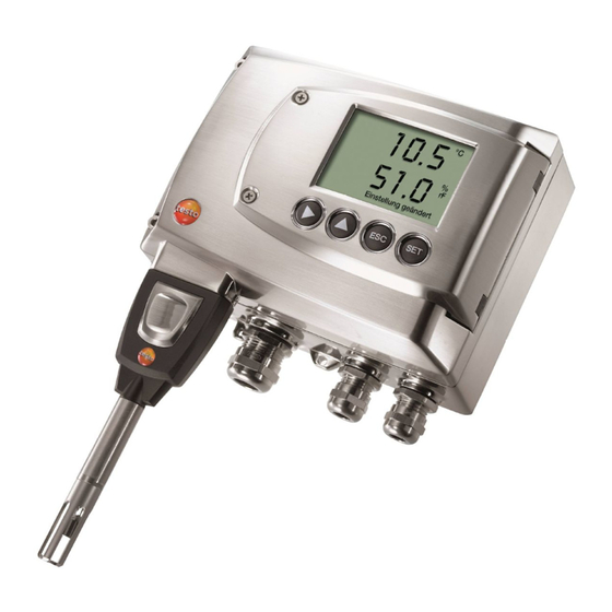
Humidity transmitter
with profibus module testo 6610.
probes p2a software. parameterizing, adjusting and analyzing software
Hide thumbs
Also See for 6681 Profibus:
- Instruction manual (154 pages) ,
- Instruction manual (86 pages) ,
- Instruction manual (85 pages)
Table of Contents
Advertisement
Quick Links
Download this manual
See also:
Instruction Manual
Advertisement
Table of Contents

Related Manuals for TESTO 6681 Profibus


Summary of Contents for TESTO 6681 Profibus
- Page 1 6681 Profibus · Humidity transmitter with Profibus module testo 6610 · Probes P2A software · Parameterizing, adjusting and analyzing software Instruction manual Volume 1...
- Page 3 Otherwise Testo will not accept any responsibility for the proper functioning of the instrument after repair and for the validity of certifications. Protecting the environment Send the product back to Testo at the end of its useful life. We will ensure that it is disposed of in an environmentally friendly manner.
- Page 4 4 About this document About this document Please read this documentation through carefully and familiarize yourself with the product before putting it to use. Keep this document to hand so that you can refer to it when necessary. Hand this documentation on to any subsequent users of the product.
- Page 5 A step is not numbered if there are no further steps or if the step is optional, e.g.: Insert probe connector into socket of testo 6681 until it engages. " to " Example entries are in inverted commas, e.g.: The value "0"...
-
Page 6: Table Of Contents
Relationship between user menu and mini-DIN socket is active ..................66 1.4.2 Key cover .................. 67 1.4.3 Password protection ..............68 1.4.4 Structure of user menu ............. 69 1.4.5 Overview of the testo 6681 user menu ........... 70 1.4.6 The individual main menus ............72... - Page 7 Contents 7 1.5 Status, warning and error messages ............. 84 1.5.1 Status messages ..............84 1.5.2 Warning messages ..............85 1.5.3 Transmitter error messages ............87 1.5.4 Status codes in cyclical service ..........88 1.5.5 Handling alarm messages ............88 1.5.6 Namur fault conditions ..............
- Page 8 8 Certificate...
-
Page 9: Transmitter
Profibus networking, for example: Process instrumentation Clean rooms Test benches Drying processes Production and storage air quality Complex room climate applications. 1.1.2 Scope of delivery The scope of delivery of the testo 6681 humidity transmitter includes the following: Key cover Rear panel bracket... -
Page 10: Accessories
6681 Profibus - 1.1 Specifications 1.1.3 Accessories The following accessories are available for the testo 6681 humidity transmitter: Protection caps for probes Mains unit P2A software (parameterizing, adjusting and analyzing software) Assembly accessories. Information about accessories and their order numbers can be found in volume 2, chapter 4.2, page 167 or on the... - Page 11 6681 Profibus - 1.1 Specifications 11 Display 2-line LCD with plain text line (optional) Housing operating temperature -40 to +70 °C/-40 to +158 °F, with display from 0 to 50 °C/+32 to +122 °F With integrated relay: -40 - +60 °C Storage temperature - 40 to 80 °C/-40 to +176 °F...
-
Page 12: Dimensions
6681 Profibus - 1.1 Specifications 1.1.5 Dimensions Dimensions in mm With M 20 cable couplings With NPT cable couplings With M plug-in connections... -
Page 13: Product Description
6681 Profibus - 1.2 Product description 13 1.2 Product description 1.2.1 At a glance Keys (with optional display) Service flap screw connection (self-locking, Display (optional) Service flap M 16 x 1.5 screw connection*, e.g. analog outputs M 16 x 1.5 screw connection*, e.g. -
Page 14: Usable Probes
21 Hole for fastening to rear panel bracket (M3 x 6 screw) 22 Plastic bracket for assembly on rear panel 1.2.2 Usable probes The testo 6681 humidity transmitter can be used with the following probes: Probe Article no. Characteristic testo 6611 0555 6610-L11 Wall probe version;... -
Page 15: Display And Keypad
-40 °C to +180 °C/-40 to +356 °F, sensor soldered 1.2.3 Display and keypad The display option allows the testo 6681 humidity transmitter to be operated via the display and four keys. The LCD display consists of two 7-segment lines for displaying readings and units and of an information line (for status messages, for example). -
Page 16: Analog Outputs
2 or optionally 3 voltage outputs of 0 to 1 V/0 to 5 V/0 to 10 V (4-wire). The transmitter can be ordered with a third analog output as an option. If the Profibus module is integrated directly into the testo 6681 humidity transmitter (order code B77), it has two current outputs 4 ...20 mA. 1.2.7 Parameters... -
Page 17: Scaling
6681 Profibus - 1.2 Product description 17 1.2.8 Scaling There are three types of min./max. values: The measuring range The maximum sensor performance is in this range. Values outside of the measuring range are displayed via messages, for example. Refer to table (see below) for the measuring range. - Page 18 6681 Profibus - 1.2 Product description Standard scaling Measuring range measuring Physical Parameter Unit Probe range at 1013 hPa MIN MAX Temperature °C 6611 °F 6611 +158 +158 °C 6612 +150 +150 °F 6612 +302 +302 °C 6613 +180 +180 °F...
-
Page 19: Alarm Handling
The testo 6681 monitors limit values using relays. If a reading is outside the limit values, a relay to be specified by the user is switched. -
Page 20: Commissioning
1.3.1 Insert Profibus module (Order no. 0554 6686) The Profibus module can be ordered retroactively as an accessory. It can easily be installed in the testo 6681 humidity transmitter. The probe connector must be disconnected. Loosen screw connection (1) of service flap and open the flap. - Page 21 6681 Profibus - 1.3 Commissioning 21 Place Profibus module (A) on lower part of instrument (4). If necessary, manually set the address using the rotary encoder switches (see chapter 1.3.3.6, page 37 before fixing the instrument in place. Set on upper part of instrument (5) and fix in place using housing screws...
-
Page 22: Assembling The Instrument
6681 Profibus - 1.3 Commissioning 1.3.2 Assembling the instrument 1.3.2.1 Wall mounting (for testo 6611/6613/6614/6615/6617 probes) Attaching rear panel bracket Remove locking screw (item (4) of drawing on page 21) and detach rear panel bracket from plastic bracket (item (2) of drawing on page 21). - Page 23 6681 Profibus - 1.3 Commissioning 23 Fastening instrument to rear panel bracket Slide plastic bracket (2) on the back of instrument onto rear panel bracket until it engages (see arrows). Insert screw (4) through hole (3) and screw into rear panel bracket.
- Page 24 6681 Profibus - 1.3 Commissioning 1.3.2.2 Duct mounting (for testo 6612 probes) Hold wall/duct bracket (order no. 0554 6651) (6) against duct wall (8) and mark drill holes for wall/duct bracket and probe shaft. Drill a hole ( 12,5 mm) in the duct wall to feed through the probe shaft.
-
Page 25: Connecting The Instrument
6681 Profibus - 1.3 Commissioning 25 Slide plastic bracket (2) on the back of the transmitter onto bracket (3, 4) until it engages. Take the weight of the transmitter into account. Ensure that the brackets (4, 6) are fastened securely. - Page 26 6681 Profibus - 1.3 Commissioning Loosen and remove housing screws (2). Important. The Profibus module (A) is already separated from the upper and lower parts of the instrument when the housing screws (2) are removed. Remove upper part of housing (3) and place on a clean surface.
- Page 27 6681 Profibus - 1.3 Commissioning 27 Warning! Electrical voltage. Danger of short-circuit! De-energize the mains connection before connecting the transmitter! Only have the transmitter wired and connected by authorized personnel with the voltage disconnected.
- Page 28 Terminal strip for voltage supply and analog outputs* 11 Eyelet for measuring point panel The transmitter testo 6681 with Alternatively, NPT cable coupling integrated Profibus module (order or M plug-in connection. code B 77) has two current outputs 4 to 20 mA.
- Page 29 6681 Profibus - 1.3 Commissioning 29 1.3.3.2 Connecting voltage supply and analog outputs Terminal strip for voltage supply and analog outputs (item (5) of Overview of terminals, chapter 1.3.3.1, page 28). Feed cable with voltage supply and analog signal lines through opened M 16 x 1.5 screw connection (item (8) in Overview of terminals, chapter...
- Page 30 6681 Profibus - 1.3 Commissioning If the channels have to be galvanically isolated, a separate mains unit must be used for each channel. Wiring diagram for 4-wire system (0 to 20 mA/4 to 20 mA/0 to 1 V/0 to 5 V/0 to 10 V)
- Page 31 6681 Profibus - 1.3 Commissioning 31 Connecting the analog outputs is only required if you also wish for analog monitoring in addition to use of the readings via Profibus (e.g. for local signal use). 1.3.3.3 Connecting the relay outputs Only have the transmitter wired and connected by authorized personnel with the voltage disconnected.
- Page 32 6681 Profibus - 1.3 Commissioning Connection note For the connection, a double-insulated mains cable (sheathed cable) with a cross-section of at least 1.5 sq. mm must be used. Cable connection (2) may not be routed in a loop within the tray (1).
- Page 33 6681 Profibus - 1.3 Commissioning 33 Use of relay as NC contact (NC = normally closed) Alarm/status light (example of installation) 250 V AC/DC, 3 A The busy light (alarm/status light) is permanently on until the relay opens or the circuit is interrupted. This circuit can...
- Page 34 6681 Profibus - 1.3 Commissioning The busy light (alarm/status light) only comes on when the relay is switched (closed). Monitoring the functionality of the alarm circuit is therefore not possible with this switching operation. Close M 20 x 1.5 screw connection (item (10) in Overview of terminals, chapter 1.3.3.1, page 28.
- Page 35 1.3.3.5 Creating the PE/earthing terminal As the testo 6681 has a metal housing, we recommend that the instrument be earthed. This can be done using the earthing terminal within the instrument (1) or the earthing terminal outside of the instrument (2).
- Page 36 6681 Profibus - 1.3 Commissioning Using the earthing terminal within the instrument Guide PE line (yellow-green) (5) through the cable coupling (x) and fit cable lug (8). Fix this to the side of the instrument (6) using M 5 screw (3), washer (4) and snap ring (7) on the internal earthing terminal (1).
- Page 37 The address of a subscriber may only be assigned once! Repeated assignment of an address leads to bus faults! In the condition on delivery for the testo 6681 with Profibus module, the switch setting FF is set. If you wish to set the address using the Profibus parameterization software, e.g.
- Page 38 6681 Profibus - 1.3 Commissioning With a Phillips screwdriver, set the address via the rotary encoder switches (1) and (2) at Profibus module (see following Section ). Insert Profibus module and close instrument (see chapter 1.3.3.7, page 40). Table of addresses...
- Page 39 6681 Profibus - 1.3 Commissioning 39...
- Page 40 6681 Profibus - 1.3 Commissioning 1.3.3.7 Closing the instrument Place Profibus module (A) on lower part of instrument (1). Set on upper part of instrument (2) and fix in place using housing screws (3).
- Page 41 6681 Profibus - 1.3 Commissioning 41 Close the service flap and tighten screws (4).
-
Page 42: Connect Instrument To The Bus System
6681 Profibus - 1.3 Commissioning 1.3.4 Connect instrument to the bus system Overview Terminati resistor Profibus Profibus Characteristics RS485 transmission technology Baud rates between 9 kBit/s and 12 Mbit/s Connected in linear structure (see Fig. above). Stubs These should be avoided, as they cause reflections on the bus and thereby disruptions in communication (especially as of transfer rates ≥... - Page 43 6681 Profibus - 1.3 Commissioning 43 Number of subscribers Master A maximum of 32 subscribers may be attached per segment (2). If more than 32 subscribers are to be integrated into the Profibus or the network dimensions are to be expanded, so-called repeaters (3) are to be installed which connect the individual bus segments with one another.
- Page 44 6681 Profibus - 1.3 Commissioning 1.3.4.1 Data transfer and baud rate With the RS485 transmission technology, the use of shielded and twisted two-wire line of cable type A is recommended in accordance with EN 50170: Loop resistance < 110 Ω/km Surge impedance 135 to 165 Ω...
- Page 45 6681 has pre-fabricated plug-and-socket connections. Using the connector (2) and the socket (1) (accessory 0554 6683), the testo 6681 can be connected to the existing cable infrastructure in the linear structure of the Profibus. The pin-assignment of the connector and the socket as per IEC 60947-5-2 is...
- Page 46 6681 Profibus - 1.3 Commissioning Alternatively, the transmitter can be connected to the bus system via a T plug-in connection (3) (accessory 0554 6687). Using the T plug-in connection (3) the field instruments (4) can be disconnected during Measuring Mode and the bus communication is not interrupted.
- Page 47 6681 Profibus - 1.3 Commissioning 47 Shielding To safeguard the Profibus from electromagnetic influences, you should use shielded cable type A data cables (see chapter 1.3.4.1, page 44). route the bus cables as far away from all live cables as possible.
- Page 48 (data exchange dependent on event such as e.g. status, warning and error messages). The testo 6681 has two measurement channels that are provided for the Profibus interface. Parameters can be found in chapter 1.2.7, page 16.
-
Page 49: Configure Profibus Module Using Edd
2 (at least version 6.0 SP2). Start the software Simatic PDM The program window is opened. In the right selection window, select the testo 6680 by double clicking. The Simatic PDM - User dialogue is opened. Select:... - Page 50 6681 Profibus - 1.3 Commissioning 1.3.5.2 Overview of user interface The individual menu items are shown in a tree structure in the left selection window (1). In the right selection window (2) input fields can be opened by clicking on the white fields (3) with the right mouse button.
- Page 51 6681 Profibus - 1.3 Commissioning 51 As the testo 6681 is the first humidity transmitter with a Profibus interface, no standardized humidity profile exists at this point, meaning that Manufacturer-specific should be selected. Input Description of the Profibus input measurement channels, i.e.
- Page 52 6681 Profibus - 1.3 Commissioning Important: The address of a subscriber may only be assigned once. Repeated assignment leads to bus faults. 1.3.5.5 Parameter settings In the Output menu item you can perform the parameter settings. To simplify the multitude of entry steps, an entry assistant is available for this.
- Page 53 The values are updated, the status was changed. Relay parameters tab In the user menu of the testo 6681 or in the P2A software, the relay status Not used or Profibus is set. Otherwise the message no access appears from Profibus.
- Page 54 The display of the relay settings is updated and the relay parameters set in the testo 6681 are applied. For usage and parameterization of the relay, testo 6686 must be equipped with the relay options (order code H01 or H02).
-
Page 55: Adjusting The Instrument
- digital signal chain. The testo 6681 transmitter has digital probes whose adjustment information is stored in the probes' internal memory. Both 1-point and 2-point adjustments can thus be carried out on another testo 6681 (e.g. in the calibration laboratory). - Page 56 In the 1-point adjustment, the reading at the working point is raised to the reference value so that there is no longer any deviation in the working point. The reference condition can be measured using a precise handheld instrument (e.g. testo 400/650 with precision humidity probe) or be created in an air conditioning cabinet.
- Page 57 % RH and °C/°F parameters. Adjusting testo 6681 using Testo handheld instrument The service flap is open, a testo 400/650 handheld instrument with a precision humidity probe is ready. Connect Testo handheld instrument 400/650 (1) with connected humidity reference probe (3) (order no.
- Page 58 6681 Profibus - 1.3 Commissioning Expose the humidity probe (4) of the testo 6681 and the reference probe (3) to the same reference conditions (e.g. in the humidity generator) and allow climatic conditions to equalize. Switch on the testo 400/650. The two-part display of the handheld instrument will show the values of the transmitter on the left, and the values of the reference probe on the right.
- Page 59 A 2-point adjustment cancels any previous 1-point adjustment. Adjustment with the standard Testo adjustment salt pots is not suitable for the testo 6614 (heated for high-humidity applications) and testo 6615 (trace humidity) probes. The reference conditions should be generated in a humidity generator to adjust these probes.
- Page 60 1.5 h (salt pots) (humidity generator) The service flap of the testo 6681 is open. Expose the humidity probe of the testo 6681 to the reference condition of 11.3 % RH for at least 1.5 hours at 25 °C.
- Page 61 6681 Profibus - 1.3 Commissioning 61 After this equalization period, press the 11.3 % adjustment key (4) for at least 10 seconds with something like a ball-point pen that is not too sharp. The LED (1) flashes when the adjustment process begins. At the same time, the 2-point adjustment 11.3 % status message appears on...
- Page 62 P2A software (see volume 2, chapter 3, page 135) or enter it via the user menu (see chapter 1.4.6.9, page 81). Disconnect connections between multimeter and contacts of the testo 6681 and close service flap. Adjusting analog output 3 (optional) If the optional third analog output is to be adjusted, a cable connection to measure the analog value must be installed.
- Page 63 Mist With the testo 6614, the rear of the Testo humidity sensor is heated, creating a microclimate around the sensor (within the filter) that is constantly 5 K warmer than the actual process conditions. As can be seen in the Mollier diagram, this reduces the relative humidity at the sensor from around 100 % RH to a lower value, e.g.
- Page 64 This means that extremely accurate measuring results are also attained to -60 °Ctd. To this end, a temperature sensor is fitted on the back of the testo 6615 which is used as a heater. A humidity and temperature value pair is taken in both the unheated and heated state.
- Page 65 6681 Profibus - 1.3 Commissioning 65 Process dew point temperature For the effectiveness of the self-adjustment the following prerequisites are decisive over the duration of the self-adjustment. The process temperature should not vary by more than 0.5K The dew point temperature should remain stable, as far as possible ...
-
Page 66: Operation
1.4.1 Relationship between user menu and mini-DIN socket is active The testo 6681 can be parameterized using either the user menu or the P2A software (see volume 2, chapter 2, page 97). The testo 6681 humidity transmitter can only be operated via the display and keypad if the display option is available. -
Page 67: Key Cover
6681 Profibus - 1.4 Operation 67 1.4.2 Key cover To prevent unauthorized operation of the keys, the standard key frame can be replaced with a key cover. If the key cover has been assembled, the service flap must be opened for operation (see Section Opening the instrument, chapter 1.3.3, page 25). -
Page 68: Password Protection
6681 Profibus - 1.4 Operation 1.4.3 Password protection The user menu can be protected with a four-digit numerical code (see Editing Main Menu Settings, chapter 1.4.6.5, page 75) so that access to the user menu is denied to unauthorized persons not familiar with this numerical code. -
Page 69: Structure Of User Menu
6681 Profibus - 1.4 Operation 69 1.4.4 Structure of user menu At the main menu level, the user menu comprises the following: Main menu of channel 1 Main menu of channel 2 Main menu of channel 3 (if this option is available) -
Page 70: Overview Of The Testo 6681 User Menu
6681 Profibus - 1.4 Operation 1.4.5 Overview of the testo 6681 user menu... - Page 71 6681 Profibus - 1.4 Operation 71...
-
Page 72: The Individual Main Menus
1.4.6 The individual main menus 1.4.6.1 Editing main menu of channel 1 An overview is given in Overview of the testo 6681 user menu, chapter 1.4.5, page 70). You can perform basic settings for channel 1. In Measuring Mode, press SET, select Main Menu Channel 1 using or ... - Page 73 6681 Profibus - 1.4 Operation 73 1.4.6.3 Editing main menu of channel 3 (if this option is available) See channel 1. 1.4.6.4 Editing Main Menu Alarm With the alarm, the relays, available as options, are programmed. In addition, the alarm statuses are shown on the display (top right) (even without relays).
- Page 74 Using alarm as collective alarm or not using it at all If the collective alarm is assigned to an alarm, the relay is switched as soon as (at least) one of the warning or error messages of the testo 6681 transmitter (or the connected testo 6610 probe) is activated.
- Page 75 6681 Profibus - 1.4 Operation 75 12 Change to another alarm using or and perform settings in the same way. 13 Continue to Main Menu Settings using or or return to Measuring Mode by pressing ESC.
- Page 76 6681 Profibus - 1.4 Operation Edit/select parameter with or , confirm with SET or cancel entry with ESC (the effect of the change in parameter can be seen during input). Backlight on 24 h Using or select On or Off and confirm with SET.
- Page 77 6681 Profibus - 1.4 Operation 77 Using ESC return to H proportion by weight and continue to Absolute pressure unit using or . Selecting absolute pressure unit (Abs. pressure unit) This parameter determines the humidity variables, standardised atmospheric dewpoint (°CtA, °FtA), relative humidity (g/kg or gr/lb) and water content...
- Page 78 6681 Profibus - 1.4 Operation 1.4.6.6 Editing Analysis main menu You can test the functionality of analog and relay outputs. In addition, you can read off the minimum and maximum values (since the last voltage supply or reset of the min./max. values).
- Page 79 6681 Profibus - 1.4 Operation 79 Testing functionality of relay outputs Press SET, choose between Alarm 1, 2, 3, 4 with or . Press SET. The relay can now be tested. You can choose between OFF and ON using ...
- Page 80 6681 Profibus - 1.4 Operation Using the P2A software (see volume 2, chapter 3, page 135) you can predefine which of the messages are to be shown in the display. In Measuring Mode, press SET, select Main Menu Message using or ...
- Page 81 6681 Profibus - 1.4 Operation 81 The type, firmware version and serial number of the transmitter are displayed. Press ESC to return to the Main Menu Ident or read off the type, firmware version and serial number of the probe using or and then press ...
- Page 82 6681 Profibus - 1.4 Operation Press SET, edit value: Scroll one digit to the right using , increase value of digit by 1 using . Confirm with SET or abort entry with ESC. Continue to Analog Adj. Ch. 1 with or .
- Page 83 6681 Profibus - 1.4 Operation 83 Select Adj. Point 2 using or . Press SET. Read off multimeter display (e.g. 12.001 mA) and enter this value in the user menu. Do this by scrolling one digit to the right using ...
-
Page 84: Status, Warning And Error Messages
Status messages, Warning messages and Error messages for either the testo 6681 or the connected testo 661x probe as applicable. All messages are stored in the transmitter with an operating hours stamp. Use the user menu (see chapter 1.4.6.7, page 79) or P2A software (see volume 2, chapter 2, page 97) to view the message history. -
Page 85: Warning Messages
2-point adjustment 80 % As part of the 2-point adjustment, an adjustment is performed at 80 % RH 02105 Self-adjustment active For testo 6615 probe only: The probe performs an automatic self-adjustment 02518 Probe reset Probe reset: The probe performs a reset 1.5.2 Warning messages... - Page 86 2-point adjustment where necessary) If the problem persists, contact Testo Service 02809 Sensor early For testo 6617 probe only: Carry out visual warning* The cover electrode of the inspection sensor is damaged; this If the mirror-like surface of may soon cause the sensor...
-
Page 87: Transmitter Error Messages
T sensor short- Short-circuit in temperature Contact Testo Service circuit sensor 0300D T sensor broken The temperature sensor is Contact Testo Service damaged (sensor broken) 03105 Self-adjustment For testo 6615 probe only: Contact Testo Service error The automatic self- adjustment was faulty... -
Page 88: Status Codes In Cyclical Service
6681 Profibus - 1.5 Status, warning and error messages 1.5.4 Status codes in cyclical service 1.5.4.1 Status codes for error messages Message Description Cause (Hexdecimal code) No probe connected 0x08 No communication Wrong probe connected Communication with probe interrupted... - Page 89 6681 Profibus - 1.5 Status, warning and error messages 89 Shown on the Message Can be used for collective alarm display start/end 2-point adjustment drift* T ambient high** T ambient low** Supply voltage low** T process high** Condensation* Values less than...
-
Page 90: Namur Fault Conditions
6681 Profibus - 1.5 Status, warning and error messages 1.5.6 Namur fault conditions If the faults named in the following table occur, the analog outputs output special values that enable a general fault warning in the higher-level control system. The values correspond to the "Namur" industry standard. -
Page 91: Maintenance And Cleaning
6681 Profibus - 1.6 Maintenance and cleaning 91 1.6 Maintenance and cleaning 1.6.1 Maintaining the instrument We recommend that the adjustment and settings of the transmitter be checked at regular intervals using the User menu (chapter 1.4, page 66) or P2A software (volume 2, chapter 2, page 97) Convenient "remote monitoring"... - Page 92 0970 6686 en 04 V01.20 V01.70-1 en-GB Vol1...
Need help?
Do you have a question about the 6681 Profibus and is the answer not in the manual?
Questions and answers