
Related Manuals for TESTO 6621


Summary of Contents for TESTO 6621
- Page 1 6621 Air-conditioning transmitter for relative humidity and temperature P2A software for testo 6621 Instruction manual...
-
Page 3: Table Of Contents
Contents 3 Contents Contents......................3 Safety and the environment................4 Part 1: testo 6621 Specifications ....................5 Product description..................10 Commissioning ..................12 Assembling the instrument ....................12 Wiring the instrument ......................14 Parameterizing/adjusting/analyzing the instrument ............16 Maintaining the product ................18 Tips and assistance ..................19 Part 2: testo P2A Software Specifications ....................20... -
Page 4: Safety And The Environment
Follow the prescribed steps when doing so. Use only OEM spare parts from Testo. Protecting the environment Send the product back to Testo at the end of its useful life. We will ensure that it is disposed of in an environmentally friendly manner. -
Page 5: Part 1: Testo 6621
Specifications Functions and use The testo 6621 is a transmitter for relative humidity and temperature. In the A01 (wall/voltage output) (see identification plate), the sensors are located in the housing; in the A02 (duct) version and the version A03 (wall/current output), the sensors are located in a permanently connected probe shaft. - Page 6 Language version of Instruction Manual Chinese-English Sample orders · Duct version with 0 - 10 V outputs, with display, neutral housing without Testo-logo, % RH, °C, open plastic cap, German/English instruction manual: 0555 6621 / A02 / B04 / C01 / E02/ F01 / G02 / M05 / K01 ·...
-
Page 7: Technical Data
· 4-wire (0 - 1 V/0 - 5 V/0 - 10 V): 20 - 30 V AC/V DC · Humidity: 0 - 100 % RH (> 90% RH only briefly) Housing · Temperature 6621-A01/A03: 0 - +60 °C/32 - 140 °F, · Material: ABS Temperature 6621-A02: -20 - +70 °C/-4 - +158 °F ·... - Page 8 6621 - Specifications Dimensions testo 6621-A01 (wall): 77,5 testo 6601-A03 (wall/current version):...
- Page 9 6621 - Product description 9 testo 6621-A02 (duct): A = length of sensor protection cap used Sensor protection cap Order code Length A in mm Sintered stainless steel filter M 01 Wire mesh filter M 02 40.3 Sintered PTFE filter...
-
Page 10: Product Description
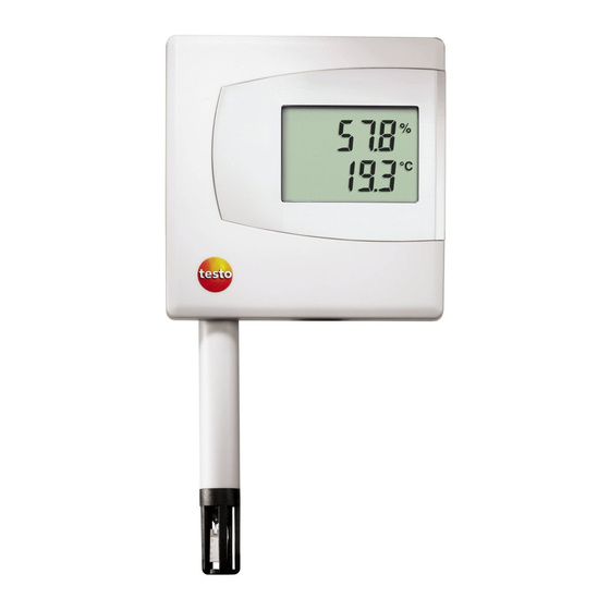
6621 - Commissioning Product description At a glance: testo 6621-A01 (wall/voltage version) Top part of housing, display (option, cannot be retrofitted) for displaying readings: 1st line Relative humidity (duct 1), 2nd line Temperature (duct 2). Mini-DIN port. Opening for feeding cable through from... - Page 11 6621 - Commissioning 11 At a glance: testo 6621-A02 (duct) Top part of housing, display (option, cannot be retrofitted) for displaying readings: 1st line Relative humidity (duct 1), 2nd line Temperature (duct 2). Mini-DIN port, protected by rubber plug.
-
Page 12: Commissioning
6621 - Commissioning Commissioning Assembling the instrument Assembling the testo 6621-A A 01/03 (wall): Please note that assembling the instrument on poorly insulated exterior walls will result in humidity and temperature readings that do not reflect the average values in the room. It is recommended that the instrument be installed on well insulated exterior or interior walls. - Page 13 6621 - Commissioning 13 Assembling the testo 6621-A A 02 (duct): Assemble the instrument according to the conditions in situ. The illustration below shows the instrument assembled on a duct with the wall/duct holder (accessory, 0554 6651) as an example:...
-
Page 14: Wiring The Instrument
6621 - Commissioning 1 2 3 4 5 6 To open the housing: Loosen the 4 screws in the upper part of the housing ( ) and remove the upper part of the housing ( ). Guide the cable through the cable coupling ( ) into the lower part of the housing. - Page 15 6621 - Maintaining the product 15 testo 6621-A A 02 (duct) View of wiring side Voltage output (4-wire, 0 - 1 V/0 - 5 V/0 - 10 V): U = 20 - 30 VAC/DC Current output (2-wire, 4 - 20 mA), max.
- Page 16 6621 - Tips and assistance 3-conductor technology (2 analog outputs active) All earth connections are connected to each other (= one common earth). Attention! Incorrect polarity wil destroy the instrument (instrument not reverse polarity-proof). Connections for voltage supply: connect common earht to pin 2! ...
-
Page 17: Parameterizing/Adjusting/Analyzing The Instrument
Switch on the testo 400/650. The values of the testo 6621 and reference humidity probe are displayed on the left and right-hand sides of the two- part display of the testo 400/650 respectively. -
Page 18: Maintaining The Product
(top right, assembled vertically on the circuit board) with distilled water or ethanol. Allow the sensor to dry completely. Cleaning the sensor of the testo 6621-A A 02 (duct), testo 6621-A A 03 (wall/current version): Do not touch sensor. -
Page 19: Tips And Assistance
Parameterizing, adjusting and analyzing software (P2A Software incl. adapter cable for USB to mini-DIN) 0554 6020 Adapter (for 1-point adjustment with testo 400/650) 0554 6022 Control and adjustment set for 2-point adjustment (11.3 % and 75.3 % RH), only for testo 6621 - A02 0554 0660 Wall/duct holder 0554 6651... -
Page 20: Part 2: Testo P2A Software
Specifications Functions and use The testo P2A Software (0554 6020) is parameterizing, adjusting and analyzing software for Testo transmitters. It is not supplied with the testo 6621. System requirements Operating system · Windows 2000 SP4, Windows XP or Windows Vista Computer ·... -
Page 21: First Steps
P2A Software - Using the product 21 First steps Installing the software / driver The CD supplied with the testo 6621 contains an update of the P2A Software including all the latest instrument drivers. Install this update once you have installed the P2A Software (0554 6020). -
Page 22: Product Description
P2A Software - Using the product Product description User interface Menu bar. Toolbar. File list: List of all instrument/parameter files. File symbols · : Instrument file, connection to the unit has not been established. · : Instrument file, connection to the unit has been established. -
Page 23: Using The Product
P2A Software - Using the product 23 Instrument information: Information displayed · Instrument files: Type, serial number, firmware version and connection status of the instrument. · Parameter file: Type, serial number and firmware version of instrument with which the parameter file was created. - Page 24 P2A Software - Using the product Saving the parameters in a parameter file: The parameter data for the selected instrument/parameter file can be saved. Only parameter data stored in the standard file can be loaded into an instrument! The required instrument/parameter file is selected.
- Page 25 Click on Adjust transmitter button. Select the adjustment point under 2-point adjustment. Position the entire testo 6621-A01 (wall) or the probe shaft of the testo 6621-A02/A03 in a precision humidity generator/air conditioning cabinet and route the USB cable to the P2A Software outwards.
- Page 26 Click on OK to confirm entries. For the testo 6621-A02/A03 (duct), a 2-point adjustment can also be performed using the testo control and adjustment set (0554 0660). Please also refer to the instruction manual for the control and adjustment set. The...
-
Page 27: Tips And Assistance
· Carry out factory reset: Click on > Click Carry out factory reset If we could not answer your question, please contact your dealer or Testo Customer Service. For contact data, see back of this document or web page www.testo.com/service-contact. - Page 28 AG Postfach 11 40, 79849 Lenzkirch Testo-Straße 1, 79853 Lenzkirch Telephone: (07653) 681-0 Fax: (07653) 681-100 E-Mail: info@testo.de Internet: http://www.testo.com 0970 6620 en 06...
Need help?
Do you have a question about the 6621 and is the answer not in the manual?
Questions and answers