Table of Contents
Advertisement
Advertisement
Table of Contents

Related Manuals for Emerson MCi210


Summary of Contents for Emerson MCi210
- Page 1 User Guide MCi210 Part Number: 0478-0033-02 Issue: 2 www.controltechniques.com...
- Page 2 General Information The manufacturer accepts no liability for any consequences resulting from inappropriate, negligent or incorrect installation or adjustment of the optional operating parameters of the equipment or from mismatching the variable speed drive with the motor. The contents of this guide are believed to be correct at the time of printing. In the interests of a commitment to a policy of continuous development and improvement, the manufacturer reserves the right to change the specification of the product or its performance, or the contents of the guide, without notice.
-
Page 3: Table Of Contents
Overview ....................13 Menus ....................13 Parameter save and restore ..............14 Remanent variables ................14 Menu 0 - MCi210 Module information ...........15 Menu 1 - User Application ..............19 Menu 2 - Ethernet configuration ............25 Menu 3 - Timer ..................32 Menu 4 - Digital I/O ................35 5.10... - Page 4 Diagnostics ................73 10.1 Run-time errors ..................73 10.2 Drive trip display codes .................73 10.3 Run-time error codes ................74 10.4 Ethernet error codes ................75 10.5 Module error codes ................76 MCi210 User Guide Issue Number: 2...
-
Page 5: Safety Information
The system designer is responsible for ensuring that the complete system is safe and designed correctly according to the relevant safety standards. MCi210 User Guide Issue Number: 2... -
Page 6: Environmental Limits
The drive contains capacitors which remain charged to a potentially lethal voltage after the AC supply has been disconnected. If the drive has been energized, the AC supply must be isolated for at least ten minutes before work may continue. MCi210 User Guide Issue Number: 2... -
Page 7: Introduction
File system User programming The MCi210 module is capable of running a CoDeSys program created by a user with the Machine Control Studio (MC Studio) software. It is an integrated development environment that supports all five of the programming languages of the IEC 61131-3 standard, including Structured Text (ST), Ladder Diagram (LD), Function Block Diagram (FBD), Sequential Function Chart (SFC) and Instruction List (IL). -
Page 8: Option Module Identification
The configuration of the host drive and System Integration option module is performed using menus and parameters. A menu is a logical collection of parameters that have similar functionality. The MCi210 module contains a number of menus that are grouped by the slot number that the module is installed into. -
Page 9: Mechanical Installation
• Align the option module above the drive as shown • Insert the option module tab into the slot on the drive • Press down on the option module until it clicks into place MCi210 User Guide Issue Number: 2... -
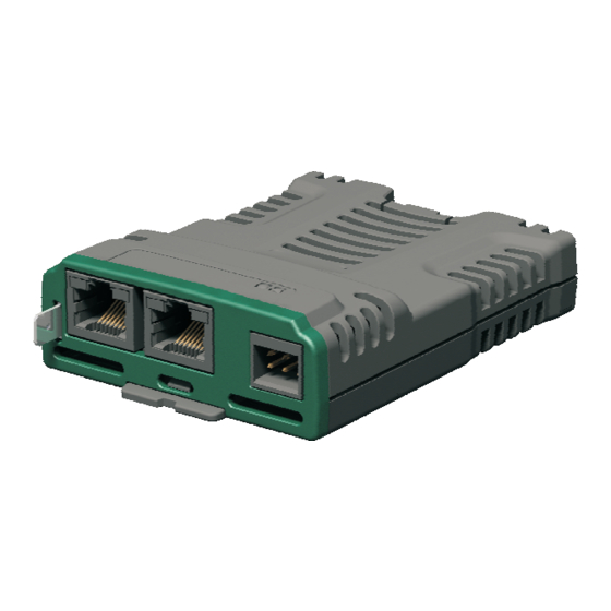
Page 10: Electrical Installation
8P8C connectors. A link/activity indicator is provided for each of the Ethernet ports. The indicators are located on the top surface of the module. The MCi210 module also provides a 6-way pluggable connector for digital inputs and outputs. Figure 4-1 MCi210... -
Page 11: Ethernet
The shells of the 8P8C (RJ45) Ethernet ports are isolated from 0V of the module and the drive. The ground tab on the MCi210 module is not required for electrical safety and is available only to increase immunity from electrical noise. -
Page 12: Digital I/O
SELV classification. WARNING The MCi210 is equipped with 3 digital inputs, 1 selectable digital input or output and 1 digital output. These inputs and outputs can be read to or controlled by the user program in the module. -
Page 13: Parameters
3 it will be accessed using Pr 2.3.010. The MCi210 module will also hold a copy of the host drive’s database. At power up, if the database held in the MCi210 is different to that of the drive, the MCi210 will upload the drive's database and overwrite the stored database. -
Page 14: Parameter Save And Restore
: INT; (* 1. Retain variable*) END_VAR PERSISTENT variables are declared in MC Studio as shown below: VAR_GLOBAL PERSISTENT RETAIN iVarPers1 : DINT; (* 1. Persistent+Retain Variable App1 *) bVarPers : BOOL; (* 2. Persistent+Retain Variable App1 *) END_VAR MCi210 User Guide Issue Number: 2... -
Page 15: Menu 0 - Mci210 Module Information
Default Units Type 16 Bit Volatile Update Rate Power-up write Display Format None Decimal Places Coding RO, ND, NC, PT, BU This parameter shows the Module ID. This is 310 for the MCi210 module. MCi210 User Guide Issue Number: 2... - Page 16 8 decimal digits and Serial Number MS (S.00.005) provides the most significant 8 decimal digits. The reconstructed serial number is ((S.00.005 x100000000) + S.00.004). For example serial number "0001234567898765" would be stored as S.00.005 = 12345, S.00.004 = 67898765. MCi210 User Guide Issue Number: 2...
- Page 17 Take care using this parameter as any configuration information will be irretrievably lost. The password for the 'root' account is not reset back to default. NOTE MCi210 User Guide Issue Number: 2...
- Page 18 Default Units Type 8 Bit Volatile Update Rate Written on power-up Display Format None Decimal Places Coding RO, ND, NC, PT, BU This parameter shows the slot number that the module is installed in. MCi210 User Guide Issue Number: 2...
-
Page 19: Menu 1 - User Application
Read / Read Number Text Binary Filtered Write only parameter parameter string parameter No default Protected Rating User Power- DE Destination value copied parameter dependent save down save Slot menu IP address address parameter MCi210 User Guide Issue Number: 2... - Page 20 This parameter indicates the status of a user program, if it is present. If no user program is present in the module then it will also indicate this. If the status indicates a run-time error (3, Error) the user's Error task may be running otherwise the user program will have stopped. MCi210 User Guide Issue Number: 2...
- Page 21 Read during Type 1 Bit User Save Update Rate initialization Display Format None Decimal Places Coding When set to 1 (On) the module may cause the drive to trip when a run-time error occurs. MCi210 User Guide Issue Number: 2...
- Page 22 When set to 0 no action will be taken and the retain data will not be saved. When set to 1 the retain data will be automatically saved when the drive enters the under voltage state. MCi210 User Guide Issue Number: 2...
- Page 23 Maximum 8448 Default Units Type 16 Bit Volatile Update Rate Written every second Display Format None Decimal Places Coding RO, ND, PT, BU This parameter displays the code for the currently active run-time error. MCi210 User Guide Issue Number: 2...
- Page 24 Decimal Places Coding RO, Txt, ND, PT, BU Value Text USER_TASK_INIT USER_TASK_EVENT0 USER_TASK_EVENT1 USER_TASK_EVENT2 USER_TASK_EVENT3 USER_TASK_POS USER_TASK_CLOCK0 USER_TASK_CLOCK1 USER_TASK_CLOCK2 USER_TASK_CLOCK3 USER_TASK_FWHEEL TASK_UNKNOWN This parameter displays the task in error for the currently active run-time error. MCi210 User Guide Issue Number: 2...
-
Page 25: Menu 2 - Ethernet Configuration
Read / Read Number Text Binary Filtered Write only parameter parameter string parameter No default Protected Rating User Power- DE Destination value copied parameter dependent save down save Slot menu IP address address parameter MCi210 User Guide Issue Number: 2... - Page 26 Coding RW, BU This parameter controls whether or not the module will attempt to use a Dynamic Host Configuration Protocol (DHCP) server to obtain an IP Address, subnet mask, default gateway and DNS servers. MCi210 User Guide Issue Number: 2...
- Page 27 If DHCP is enabled (DHCP Enable (S.02.005)) this parameter becomes read-only and, until an IP Address is allocated to the module, will display 0.0.0.0. If DHCP is disabled the module will initialize, on reset or power cycle, with the subnet mask stored for the parameter. MCi210 User Guide Issue Number: 2...
- Page 28 If DHCP is enabled (DHCP Enable (S.02.005)) this parameter becomes read-only and, until an IP Address is allocated to the module, will display 0.0.0.0. If DHCP is disabled the module will initialize, on reset or power cycle, with the primary DNS address stored for the parameter. MCi210 User Guide Issue Number: 2...
- Page 29 A tick period of 1 ms will be given to the highest priority fieldbus protocol, 5 ms to all other fieldbus protocols (equal priority). If no fieldbus protocol has been selected to have priority over others, all protocols will have equal priority and a tick rate of 5 ms. MCi210 User Guide Issue Number: 2...
- Page 30 Type 16 Bit User Save Update Rate Read on module reset Display Format None Decimal Places Coding RW, BU This parameter specifies the MTU (Maximum Transmittable Unit) in bytes allowed by the Ethernet interface. MCi210 User Guide Issue Number: 2...
- Page 31 Display Format None Decimal Places Coding RW, BU This parameter specifies the VLAN ID that the interface will be a member of. Any packets entering the switch without this VLAN ID will not be handled. MCi210 User Guide Issue Number: 2...
-
Page 32: Menu 3 - Timer
1 = External clock provided on digital input (DigIn1 or DigIn2, b9 depending) Internal Clock Rate: • 0 = 50 MHz 5 to 6 • 1 = 12.5 MHz • 2 = 3.125 MHz • 3 = 0.78125 MHz MCi210 User Guide Issue Number: 2... - Page 33 Units Type 8 Bit Volatile Update Rate Immediate Display Format Binary Decimal Places Coding RO,ND,NC, BU This parameter displays the status of the module's Timer Unit. The following table details the status word bits. MCi210 User Guide Issue Number: 2...
- Page 34 Timer Counter (S.03.003)) reaches this value bit 0 of Timer Unit Status Word (S.03.002) will be set if the Timer Unit is configured to be in free running mode (see Timer Unit Control Word (S.03.001)). MCi210 User Guide Issue Number: 2...
-
Page 35: Menu 4 - Digital I/O
Decimal Places Coding RO, ND, NC, PT When read, this parameter will indicate the state of Digital Input 1. An inactive input (low) will give the value 0 and active input (high) will give 1. MCi210 User Guide Issue Number: 2... - Page 36 Display Format None Decimal Places Coding When written, this parameter will set the state of Digital Output 5. Setting to 0 will place the output low and setting to 1 will place the output high. MCi210 User Guide Issue Number: 2...
- Page 37 1 Bit Volatile Update Rate Immediate Display Format None Decimal Places Coding Setting this parameter to 0 will configure Digital I/O 4 as an input. Setting it to 1 will configure it as an output. MCi210 User Guide Issue Number: 2...
-
Page 38: Menu 9 - Resources
Cyclic Tx Links Free Minimum Maximum Defaultf Units Type 8 Bit Volatile Update Rate Background write Display Format None Decimal Places Coding RO, ND, NC, BU This parameter shows the number of available transmit cyclic links. MCi210 User Guide Issue Number: 2... - Page 39 Synchronous Task % Free Minimum Maximum Default Units Type 8 Bit Volatile Update Rate Background write Display Format None Decimal Places Coding RO, ND, NC, BU This parameter shows the current resource available for the synchronous task. MCi210 User Guide Issue Number: 2...
-
Page 40: Menu 10 - Easy Mode Cyclic Data
S.10.051 S.10.052 S.10.053 S.10.054 S.10.060 S.10.061 S.10.062 S.10.063 S.10.064 The Easy Mode Cyclic Data links can be made synchronous links by setting a value in Tx Link Maximum Network Delay (S.11.030, S.11.031 or S.11.032). MCi210 User Guide Issue Number: 2... - Page 41 S.10.032 Tx3 Source Parameter 0 to 4.99.999 0.00.000 S.10.033 Tx3 Parameter Count 0 to 32 Unicast (0), Broadcast (1), Muliticast1 (2), Tx3 Link Transmission S.10.034 Multicast2 (3), Unicast (0) Type Multicast3 (4), Multicast4 (5) MCi210 User Guide Issue Number: 2...
- Page 42 Trip (0), Clear output (1), S.10.056 Rx2 Timeout Action Trip (0) Hold last (2) This slot (0), Slot 1 (1), Rx2 Timeout Event S.10.057 Slot 2 (2), This slot (0) Destination Slot 3 (3), Slot 4 (4) MCi210 User Guide Issue Number: 2...
- Page 43 Read / Read Number Text Binary Filtered Write only parameter parameter string parameter No default Protected Rating User Power- DE Destination value copied parameter dependent save down save Slot menu IP address address parameter MCi210 User Guide Issue Number: 2...
- Page 44 Reset (S.10.002) to On (1), or reset the module by setting Reset Module (S.00.007) to On (1). This parameter will be automatically set to Off (0) when the default operation has been completed. MCi210 User Guide Issue Number: 2...
- Page 45 Update Rate Read on reset Display Format None Decimal Places Coding RW, BU This parameter is used to set the link number for the transmit link. This number should be unique for each transmit link. MCi210 User Guide Issue Number: 2...
- Page 46 Tx1 Link Transmission Type S.10.024 Tx2 Link Transmission Type S.10.034 Tx3 Link Transmission Type Minimum Maximum Default Units Type 8 Bit User Save Update Rate Read on reset Display Format None Decimal Places Coding RW, TE, BU MCi210 User Guide Issue Number: 2...
- Page 47 S.10.019 Tx1 Link Status S.10.029 Tx2 Link Status S.10.039 Tx3 Link Status Minimum Maximum Default Units Type 32 Bit User Save Update Rate Write on reset Display Format None Decimal Places Coding RO, Txt MCi210 User Guide Issue Number: 2...
- Page 48 If this parameter is set to a non-zero value then Rx Link Destination Parameter (S.10.042, S.10.052 or S.10.062) and Rx Link Parameter Count (S.10.043, S.10.053 or S.10.063) will become read-only with value of 0. MCi210 User Guide Issue Number: 2...
- Page 49 This parameter is used to set the number of contiguous parameters for the receive link. If a profile has been selected in Rx Link Profile (S.10.040, S.10.050 or S.10.060) then this parameter will become read-only with value of 0. MCi210 User Guide Issue Number: 2...
- Page 50 S.10.056 or S.10.066). It is good system design to allow for some message loss by setting the timeout duration NOTE to be greater than the transmit period by a factor of 2 or more. MCi210 User Guide Issue Number: 2...
- Page 51 Trigger module event in slot 3 Slot 4 Trigger module event in slot 4 This parameter defines the slot in which an event will occur if a cyclic data timeout occurs on the receive link. MCi210 User Guide Issue Number: 2...
- Page 52 8 Bit Volatile Update Rate Write on reset Display Format None Decimal Places Coding RO, Txt Value Text Invalid profile Invalid mapping Read only param Timeout In error Link num in use Not editable MCi210 User Guide Issue Number: 2...
- Page 53 Out of memory This parameter shows status of receive link if it has been configured. A reset of the menu by setting Reset (S.10.002) to On (1) is required for any changes to take effect. MCi210 User Guide Issue Number: 2...
-
Page 54: Menu 11 - Synchronization
Slot 2 (2), This slot (0) Frame Destination Slot 3 (3), Slot 4 (4) No event (0), Event (1), Rx3 Late Synchronization S.11.062 Event1 (2), No event (0) Frame Event Event2 (3), Event3 (4) MCi210 User Guide Issue Number: 2... - Page 55 Background write Display Format Mac Address Decimal Places Coding RW, ND,NC, PT, BU This parameter displays the MAC address, as a 64 bit hexadecimal value, of the synchronization grandmaster (if there is a grandmaster). MCi210 User Guide Issue Number: 2...
- Page 56 Type 1 Bit User Save Update Rate Immediate Display Format None Decimal Places Coding This parameter controls whether the module synchronizes the OPT_SYNC with the network grandmaster. A value of On (1) inhibits this. MCi210 User Guide Issue Number: 2...
- Page 57 RW, Txt, BU Value Text 802.3 This parameter selects the transport layer to use. 0 = Layer 2 Ethernet; 1 = UDP. Layer 2 Ethernet packet sizes are smaller than the packet sizes of UDP. NOTE MCi210 User Guide Issue Number: 2...
- Page 58 This parameter controls the rate at which PTP Sync frames are sent. The message rate is determined by raising 2 to the power of this parameter. E.g the default value of -2, results in four sync messages per second. MCi210 User Guide Issue Number: 2...
- Page 59 Trip drive with Slotx Error and sub-trip code Do not use The data is ignored The data is used immediately This parameter defines the action to be taken when a late synchronized frame is received. MCi210 User Guide Issue Number: 2...
- Page 60 Trigger module event 3 The parameter defines the event to trigger in the given destination, as specified in Rx Link Late Synchronization Frame Destination (S.11.041, S.11.051 or S.11.061), if a late synchronized frame is received. MCi210 User Guide Issue Number: 2...
-
Page 61: Menu 15 - Modbus
Minimum Maximum Default Units Type 1 Bit User Save Update Rate Background read Display Format None Decimal Places Coding RW, BU This parameter is used to enable or disable Modbus master and slave functionality. MCi210 User Guide Issue Number: 2... - Page 62 Description No error No error Port in use Specified port is currently in use by another protocol Timeout event Timeout trigger event location is not valid This parameter will indicate any Modbus configuration errors. MCi210 User Guide Issue Number: 2...
- Page 63 MCi210 User Guide Issue Number: 2...
- Page 64 Coding RW, Txt, BU Value Text Description Trip Trip drive and raise error No action No action Defines the action when no message is received within the time period specified in Modbus timeout (S.15.009). MCi210 User Guide Issue Number: 2...
- Page 65 Trigger module Event 3 Trigger Event 4 Trigger module Event 4 Defines the event to trigger when a timeout occurs. Modbus Timeout Event Destination (S.15.011) must specify an appropriate consumer (slot option) of the event. MCi210 User Guide Issue Number: 2...
- Page 66 Read on module reset, Type 32 Bit User Save Update Rate Modbus interface reset or Modbus interface enable Display Format IP Address Decimal Places Coding RW, BU This parameter specifies an IP Address for a priority connection. MCi210 User Guide Issue Number: 2...
- Page 67 Read on module reset, Type 32 Bit User Save Update Rate Modbus interface reset or Modbus interface enable Display Format IP Address Decimal Places Coding RW, BU This parameter specifies an IP Address for a priority connection. MCi210 User Guide Issue Number: 2...
-
Page 68: Variable Allocation Menus
The parameters that can be associated are in the following menus and ranges. Pr 70.000 to Pr 70.255 Pr 71.000 to Pr 71.255 Pr 72.000 to Pr 72.255 Pr 73.000 to Pr 73.255 Pr 74.000 to Pr 74.255 Pr 75.000 to Pr 75.255 MCi210 User Guide Issue Number: 2... -
Page 69: Digital I/O
Digital I/O The MCi210 is equipped with three dedicated digital input terminals, one configurable digital input/ output terminal and one dedicated digital output terminal. The digital outputs are positive logic such that they are at 24 V when active and will supply up to 20 mA of current. -
Page 70: Timer
Timer The MCi210 module offers timer functionality. The Timer Unit can be configured to be clocked from one of two digital inputs or the module's internal clock. When the internal clock is used, the frequency can be selected from four possible values; 50 MHz, 12.5 MHz, 3.125 MHz and 781.25 kHz. - Page 71 Figure 8-1 Overview of the Timer Unit MCi210 User Guide Issue Number: 2...
-
Page 72: User Programming
(ST), Function Block Diagram (FBD), Ladder Diagrams (LD), Sequential Function Chart (SFC) and Instruction List (IL). Machine Control Studio is specifically for use with MCi210 and Unidrive M onboard target and cannot be used to develop applications for other manufacturers' products. -
Page 73: Diagnostics
SlotX Different the option module with another one of the same ID number will not initiate this trip. The trip will also occur if an option module is installed to a previously unused slot. MCi210 User Guide Issue Number: 2... -
Page 74: Run-Time Error Codes
Error in UDINT value range. The provided UDINT value UDINT range err is out of the specified limits. User Requested The user has requested to rise an error and trip the drive. Watchdog err Watchdog error. A user task has overrun. MCi210 User Guide Issue Number: 2... -
Page 75: Ethernet Error Codes
INIT SMTP Email (SMTP) initialization error INIT Ethernet/IP Ethernet/IP initialization error INIT TCP/IP TCP/IP initialization error Ethernet Failure Ethernet controller initialization error E/IP PLC IDLE Ethernet/IP PLC Idle Sync Task ORun Synchronous task overrun MCi210 User Guide Issue Number: 2... -
Page 76: Module Error Codes
Configuration file restore error Self Test Error Power on self test error Runtime Config Runtime configuration error Processor except The processor has entered the exception state Task Starvation System task starvation Runtime except Runtime exception MCi210 User Guide Issue Number: 2... - Page 77 Parameter save and restore ...............14 Parameters ....................13 Remanent variables ...................14 Reset Module .....................17 Run-time error codes ..................74 Run-time errors ..................73 Safety ......................5 Subnet Mask ....................27 Tasks ......................7 Timer ....................32, 70 User programming ..................7, 72 MCi210 User Guide Issue Number: 1...
- Page 78 0478-0033-02...
Need help?
Do you have a question about the MCi210 and is the answer not in the manual?
Questions and answers