Emerson M400 Quick Start Manual
Supervisory controller setup with vfd drive
Hide thumbs
Also See for M400:
- User manual (198 pages) ,
- Quick start quide (36 pages) ,
- Quick start manual (4 pages)
Advertisement
Quick Links
Supervisory Controller Setup with
M400 VFD Drive
Quick Start Guide
This document will guide you through setting up and
commissioning the M400 VFD Drive in Supervisory
Controllers (E3 and Site Supervisor).
Complete All Programming Before you set up the M400
Drive.
Note that the M400 Drive requires Supervisory Controller
firmware version 2.14F01 and above.
The keypad and display gives information about the
operating status of the drive and trip codes. It provides
the ability to change parameters, stopping and starting
the drive, and the ability to perform a drive reset.
Keypad Number
The Enter button is used to enter
1 (Enter)
parameter view or edit mode, or to
accept a parameter edit.
The Navigation keys can be used to
select individual parameters or to edit
2 (Navigation)
parameter values. In keypad mode, the
"Up" and "Down" keys are alsoused to
increase or decrease the motor speed.
The Start key is used to start the drive in
3 (Start)
keypad mode.
The Stop / Reset key is used to stop and
reset the drive in keypad mode. It can
4 (Stop/Reset)
also be used to reset the drive in
terminal mode.
The Escape key is used to exit from the
5 (Escape)
parameter edit / view mode or
disregard a parameter edit.
Document Part # 026-4176 Rev 1
©2022 Emerson Digital Cold Chain, Inc. This document may be photocopied for personal use.
Visit our website at www.climate.emerson.com for the latest technical documentation and updates.
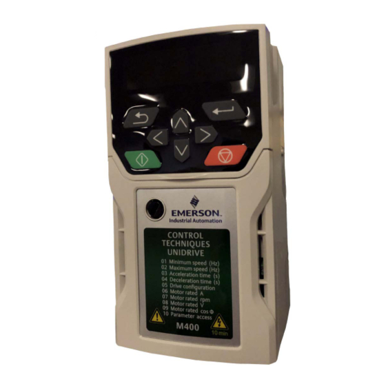
Keypad Description
Figure 1 - Unidrive M400
Figure 2 - Unidrive M400 Keypad Details
Page 1 of 16
Advertisement

Related Manuals for Emerson M400


Summary of Contents for Emerson M400
- Page 1 Document Part # 026-4176 Rev 1 Page 1 of 16 ©2022 Emerson Digital Cold Chain, Inc. This document may be photocopied for personal use. Visit our website at www.climate.emerson.com for the latest technical documentation and updates.
- Page 2 Max # of Instances Document Part # 026-4176 Rev 1 Page 2 of 16 ©2022 Emerson Digital Cold Chain, Inc. This document may be photocopied for personal use. Visit our website at www.climate.emerson.com for the latest technical documentation and updates.
- Page 3 • Set the Com Port baud to 19.2 Document Part # 026-4176 Rev 1 Page 3 of 16 ©2022 Emerson Digital Cold Chain, Inc. This document may be photocopied for personal use. Visit our website at www.climate.emerson.com for the latest technical documentation and updates.
- Page 4 • If VFD is the last device at the end of Com segment, terminate with 150 ohms between terminals 2 and 3. Document Part # 026-4176 Rev 1 Page 4 of 16 ©2022 Emerson Digital Cold Chain, Inc. This document may be photocopied for personal use. Visit our website at www.climate.emerson.com for the latest technical documentation and updates.
- Page 5 • If VFD is the last device at end of Com segment, terminate with 150 ohms between terminals 2 and 3. Document Part # 026-4176 Rev 1 Page 5 of 16 ©2022 Emerson Digital Cold Chain, Inc. This document may be photocopied for personal use. Visit our website at www.climate.emerson.com for the latest technical documentation and updates.
- Page 6 Figure 7 - Site Supervisor to M400 (MODBUS) Document Part # 026-4176 Rev 1 Page 6 of 16 ©2022 Emerson Digital Cold Chain, Inc. This document may be photocopied for personal use. Visit our website at www.climate.emerson.com for the latest technical documentation and updates.
- Page 7 Figure 8 - Site Supervisor to M400 (ANALOG 0-10V) Document Part # 026-4176 Rev 1 Page 7 of 16 ©2022 Emerson Digital Cold Chain, Inc. This document may be photocopied for personal use. Visit our website at www.climate.emerson.com for the latest technical documentation and updates.
- Page 8 Figure 9 - Lumity E3 to M400 (MODBUS) Document Part # 026-4176 Rev 1 Page 8 of 16 ©2022 Emerson Digital Cold Chain, Inc. This document may be photocopied for personal use. Visit our website at www.climate.emerson.com for the latest technical documentation and updates.
- Page 9 Figure 10 - Lumity E3 to M400 (ANALOG 0-10V) Document Part # 026-4176 Rev 1 Page 9 of 16 ©2022 Emerson Digital Cold Chain, Inc. This document may be photocopied for personal use. Visit our website at www.climate.emerson.com for the latest technical documentation and updates.
- Page 10 STEP 5: Commissioning the Device to the Supervisory Controller From the Control Inventory screen select the Modbus address for the M400 and click the checkmark to save and start commissioning. (Best practices tip: set the Modbus number to match the connected Com Port and the Address to match the M400 addressing in STEP 1).
- Page 11 Figure 13 - Inputs Tab Document Part # 026-4176 Rev 1 Page 11 of 16 ©2022 Emerson Digital Cold Chain, Inc. This document may be photocopied for personal use. Visit our website at www.climate.emerson.com for the latest technical documentation and updates.
- Page 12 Figure 15 - M400 VFD Device Status Document Part # 026-4176 Rev 1 Page 12 of 16 ©2022 Emerson Digital Cold Chain, Inc. This document may be photocopied for personal use. Visit our website at www.climate.emerson.com for the latest technical documentation and updates.
- Page 13 Figure 17 - Application Commands - NVM_SAVE Document Part # 026-4176 Rev 1 Page 13 of 16 ©2022 Emerson Digital Cold Chain, Inc. This document may be photocopied for personal use. Visit our website at www.climate.emerson.com for the latest technical documentation and updates.
-
Page 14: Step 6: Verification Of Settings
• REF FREQ (the speed setting of the motor) Document Part # 026-4176 Rev 1 Page 14 of 16 ©2022 Emerson Digital Cold Chain, Inc. This document may be photocopied for personal use. Visit our website at www.climate.emerson.com for the latest technical documentation and updates. - Page 15 Figure 19 - Setting Up Inputs Tab 2. Use Table 1- Menu 0 Guide to verify values set in the M400 drive. Note: Table 1- Menu 0 Guide gives diagnostic information about the system. It allows you to double check to make sure that the E2 controller sent the correct parameters.
- Page 16 The contents of this publication are presented for informational purposes only and they are not to be construed as warranties or guarantees, express or implied, regarding the products or services described herein or their use or applicability. Emerson reserves the right to modify the designs or specifications of such products at any time without notice. Responsibility for proper selection, use and maintenance of any product remains solely with the...
Need help?
Do you have a question about the M400 and is the answer not in the manual?
Questions and answers